MKFARI60CONTROLLER
Kenwo Industries Limited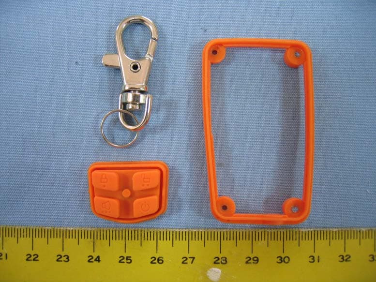
Click to zoom
Application Details
- Equipment Class
- DSC - Part 15 Security/Remote Control Transmitter
- Date of Grant
- May 17, 2006
- Application Purpose
- Original Equipment
- Date of Application
- May 17, 2006
- Equipment Note
- CONTROLLER
- Frequency Range
- 433.92000000 - 433.92000000
- Company
- Kenwo Industries Limited
- Country
- Hong Kong
Documents & Files
Document Text
Text extracted from the exhibit documents filed with the FCC. Open a document above to read the original.
Users Manual
TRS-60 CONTROLLER INSTALLATION MANUAL AND USER’S GUIDE FCC Notice This device complies with part 15 of the FCC Rules. Operation is subject to the following two conditions: (1) This device may not cause harmful interference, and (2) this device must accept any interference received, including interference that may cause undesired operation. Changes or modifications not expressly approved by the party responsible for com p liance could void the user’s authorit y to o p erate this device. For technical assistance with any of the procedures on this manual, or for warranty claimsplease contact Aritronix at. www.scorpioalarms.com [email protected] Toll Free (800)428-0440 International (480)951-1109 Aritronix Ltd 16055 N. Dial Blvd. Suite B-10 Scottsdale , AZ 85260 Limited Warranty Scorpio-branded security products come with a 2-year (from time of purchase) limited warranty. This includes all components and accessories that are manufactured by Aritronix Ltd. The following sections describe the limited warranties. What is covered by this limited warranty? This limited warranty covers defects in materials and workmanship in your — our end-user customer's — Scorpio-branded hardware products, including Scorpio-branded accessory products. What is not covered by this limited warranty? This limited warranty does not cover cosmetic damage, damage/failure due to acts of God: Problems that result from: • External causes such as accident, abuse, misuse, or problems with electrical power • Usage that is not in accordance with product instructions or modifications of the product • Failure to follow the product instructions • Problems caused by using accessories, parts, or components not manufactured or approved by Scorpio What should you do if you experience a problem with a Scorpio product? Firstly contact Aritronix, Ltd. using one of the methods listed below. [Proof of purchase, installer and motorcycle information will be requested}. If after assistance from our trained staff it is determined that the Scorpio product may be faulty then you will providewith detailed information on processing a warranty claim. All warranty claims must contain a return authorization number (RA#). Aritronix, Ltd. will not accept any package that does not have been accepted for warranty repair/exchange Note: The system has to be correctly installed for at least 12 hours before full function of the back-up battery can be used. Note: If the system chirps only 2 times and it has been correctly connected for more the 12 hours the battery needs replacement. (Contact Aritronix for replacement options) Standard Features • ½ mile 2-Way FM Transceiver • LCD Water proof / impact resistant remote • Ultra low power drain MCM • Built-in accelerometer • Ignition protection • Range Confirmation Signal (RCS) • Remote sensor control • Battery safeguard with “sleep mode” • Violation display with time stamp • Passive arming • Selectable arming / disarming • Programmable multi-tone siren • Remote panic feature Optional Accessories • Perimeter sensor (SN-5) – A miniature multi stage microwave sensor that detects motion in mass around the motorcycle. • Ignition disable and anti-hijack kit (RID-5) - Allows remote disabling of the motorcycle’s electrical system, should someone force you off your bike. Also prevents the engine from being started when the system is armed. • Back-up battery (BAT-5) – A built-in back-up battery feature allowing the siren and transmitter to continue operating when power is interrupted. • Factory Connector Kits –OEM style connectors that simply plug into the motorcycle’s factory wiring harness. Connector kits are available for select motorcycle models. Table of Contents Installation • Component List ---------------------------------------------------------------- Page 3 • Planning The Installation ---------------------------------------------------- Page 3 • Mounting The Components ----------------------------------------------- Page 4 • Color Codes --------------------------------------------------------------------- Page 4 • Connections --------------------------------------------------------------------- Page 5 • Using the T-tap ------------------------------------------------------------------ Page 5 User’s Guide • Remote Transceiver Icons and Message Display ------------------- Page 6 • Transceiver Charging Instructions ---------------------------------------- Page 6 • Transceiver Battery Status --------------------------------------------------- Page 6 • Operating the transceiver -------------------------------------------------- Page 7 • Alarm Triggers-------------------------------------------------------------------- Page 7 - 8 • Sensor Memory Display ------------------------------------------------------ Page 8 • RCS (Range Conformation Signal) -------------------------------------- Page 8 • Motorcycle Battery Status -------------------------------------------------- Page 8 • Battery Safeguard with “Sleep Mode” -------------------------------- Page 8 • Locking the Transceiver’s buttons --------------------------------------- Page 8 • Checking Motorcycle Status and Violation Display --------------- Page 9 • Programming and customizing Instructions -------------------------- Page 9 -11 • Encoding a Transceiver ------------------------------------------------------ Page 11 Optional Accessories Instructions • Perimeter Sensor (SN-5) ------------------------------------------------------ Page 13 • Ignition Disable / Anti-hijack Unit ----------------------------------------- Page 14 • Back-up Battery ---------------------------------------------------------------- Page 15 Warranty and FCC Information • Limited Warranty ------------------------------------------------------------- Page 16 • FCC Notice ---------------------------------------------------------------------- Page 16 • Contact information --------------------------------------------------------- Page 16 1 Back-up Battery (BAT-5) The back-up battery provid…
Text truncated - open the document above for the full version.
Block Diagram
KENWO INDUSTRIES LIMITED TRS-60 BLOCK DIAGRAM ( REMOTE ) RX-in TX-out LNA T/R Switch MCU 32.768KHz CRYSTAL Drive PA Change circuit 3.7V Battery Perimeter Sensor MOTOR LCD BUZZER ANT RX Power Tx Power RF Module 13.2531MHz CRYSTAL
External Photos
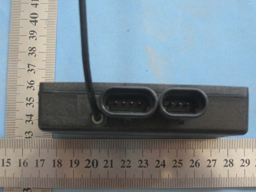
Spectrum Research & Testing Lab., Inc. No. 101-10, Ling 8, Shan-Tong Li, Chung-Li City, Taoyuan, Taiwan Tel: 886-3-4987684 Fax: 886-3-4986528 Photo Page: 1 of 6 PHOTOS OF EUT-CONTROLLER, MODEL NO.:TRS-60 Spectrum Research & Testing Lab., Inc. No. 101-10, Ling 8, Shan-Tong Li, Chung-Li City, Taoyuan, Taiwan Tel: 886-3-4987684 Fax: 886-3-4986528 Photo Page: 3 of 6 PHOTOS OF EUT -CASE Spectrum Research & Testing Lab., Inc. No. 101-10, Ling 8, Shan-Tong Li, Chung-Li City, Taoyuan, Taiwan Tel: 886-3-4987684 Fax: 886-3-4986528 Photo Page: 5 of 6 PHOTOS OF EUT-BATTERY Spectrum Research & Testing Lab., Inc. No. 101-10, Ling 8, Shan-Tong Li, Chung-Li City, Taoyuan, Taiwan Tel: 886-3-4987684 Fax: 886-3-4986528 Photo Page: 6 of 6 PHOTOS OF EUT- ACCESSORIES
ID Label/Location Info
Spectrum Research & Testing Lab., Inc. No. 101-10, Ling 8, Shan-Tong Li, Chung-Li City, Taoyuan, Taiwan, R.O.C. Sample of ID Label The device is so small that the 2 parts warning statement does not have to go on the device. It will be really hard to read. We remove the 2 parts statement from the device since we already have it in the manual. FCC ID:MKFARI60
Internal Photos
Spectrum Research & Testing Lab., Inc. No. 101-10, Ling 8, Shan-Tong Li, Chung-Li City, Taoyuan, Taiwan Tel: 886-3-4987684 Fax: 886-3-4986528 Photo Page: 2 of 6 PHOTOS OF EUT Spectrum Research & Testing Lab., Inc. No. 101-10, Ling 8, Shan-Tong Li, Chung-Li City, Taoyuan, Taiwan Tel: 886-3-4987684 Fax: 886-3-4986528 Photo Page: 4 of 6 PHOTOS OF EUT-PCB
Operational Description
Spectrum Research & Testing Lab., Inc. No. 101-10, Ling 8, Shan-Tong Li, Chung-Li City, Taoyuan, Taiwan, R.O.C. Operational Description of equipment CONTROLLER FCC ID: MKFARI60 When push/choose key switch, the CONTROLLER will send a signal and local oscillator will go on, then transmitting signal. When RX get a modulation signal: 1. The car computer will check the signal and demodulate the signal. 2. Signals go through low- passed filter and send signal to CPU. 3. CPU will process the signal. 4. When relative Relay in RX go on, it can control the PDA, phone,. ...etc.. PRODUCT CONTROLLER MODEL NO. TRS-60 POWER SUPPLY 3.7Vdc(Battery) CABLE N/A I/O PORT/INTERFACE N/A FREQUENCY BAND UHF CARRIER FREQUENCY 433.92MHz NUMBER OF CHANNEL 1 CHANNEL SPACING N/A I.F. & L.O. L.O.: 433.92MHz MODULATION TYPE FSK BIT RATE OF TRANSMISSION 2400 Bit/S ANTENNA TYPE Integral Antenna
Test Report
Spectrum Research & Testing Lab., Inc. No. 101-10, Ling 8, Shan-Tong Li, Chung-Li City, Taoyuan, Taiwan, R.O.C. TEST REPORT Reference No.: D06041805 Report No.: FCCD06041805 Page: 2 of 20 Date: May 16, 2006 FCC ID: MKFARI60 Table of Contents 1. DOCUMENT POLICY AND TEST STATEMENT................................................... 3 1.1 DOCUMENT POLICY .......................................................................................... 3 1.2 TEST STATEMENT ............................................................................................. 3 2. DESCRIPTION OF EUT AND TEST MODE ......................................................... 4 2.1 GENERAL DESCRIPTION OF EUT .................................................................... 4 2.2 DESCRIPTION OF EUT INTERNAL DEVICE ..................................................... 4 2.3 DESCRIPTION OF TEST MODE......................................................................... 4 2.4 DESCRIPTION OF SUPPORT UNIT................................................................... 5 3. DESCRIPTION OF APPLIED STANDARDS......................................................... 5 4. CONDUCTED EMISSION TEST .......................................................................... 5 5. RADIATED EMISSION TEST ............................................................................... 6 5.1 RADIATED EMISSION LIMIT .............................................................................. 6 5.2 TEST EQUIPMENT ............................................................................................. 7 5.3 TEST SET-UP...................................................................................................... 8 5.4 TEST PROCEDURE............................................................................................ 8 5.5 EUT OPERATING CONDITION........................................................................... 8 5.6 MAXIMUM MODULATION PERCENTAGE ......................................................... 8 5.7 RADIATED EMISSION TEST RESULT................................................................ 9 6. BAND EDGE TEST ............................................................................................ 10 6.1 BAND EDGE LIMIT ............................................................................................10 6.2 TEST EQUIPMENT ............................................................................................10 6.3 TEST SET-UP.....................................................................................................11 6.4 TEST PROCEDURE...........................................................................................11 6.5 EUT OPERATING CONDITION .....................................................................11 6.6 BAND EDGE TEST RESULT .........................................................................11 7. FREQUENCY BANDWIDTH............................................................................... 13 7.1 FREQUENCY BANDWIDTH LIMIT ....................................................................13 7.2 TEST EQUIPMENT ............................................................................................13 7.3 TEST SET-UP.....................................................................................................13 7.4 TEST PROCEDURE...........................................................................................13 7.5 EUT OPERATING CONDITION .....................................................................14 7.6 FREQUENCY BANDWIDTH TEST RESULT .................................................14 PASS/FAIL ................................................................................................................ 14 8. RELEASE OR OPERATING TIME....................................................................... 16 8.1 RELEASE TIME OR OPERATING LIMIT ...........................................................16 8.2 TEST EQUIPMENT ............................................................................................16 8.3 TEST SET-UP.....................................................................................................16 8.4 TEST PROCEDURE............................................................................................17 8.5 EUT OPERATING CONDITION...........................................................................17 8.6 RELEASE OR OPERATING TIME TEST RESULT..............................................17 9. PHOTOS OF TESTING ....................................................................................... 19 10. TERMS OF ABRIVATION ................................................................................. 20 Spectrum Research & Testing Lab., Inc. No. 101-10, Ling 8, Shan-Tong Li, Chung-Li City, Taoyuan, Taiwan, R.O.C. TEST REPORT Reference No.: D06041805 Report No.: FCCD06041805 Page: 3 of 20 Date: May 16, 2006 FCC ID: MKFARI60 1. DOCUMENT POLICY AND TEST STATEMENT 1.1 DOCUMENT POLICY - The report shall not be reproduced except in full, without the written approval of SRT Lab, Inc. - The report must not be used by the applicant to claim that the product is endorsed by NVLAP. - The NVLAP logo applies only to the applicable standards specified in this report. 1.2 TEST STATEMENT - The test results in the report apply only to the unit tested by SRT Lab. - There was no deviation from the requirements of test standards during the test. - The new battery power source 3.7Vdc, was used during the test. - The antennas were soldered on the PCB. Spectrum Research & Testing Lab., Inc. No. 101-10, Ling 8, Shan-Tong Li, Chung-Li City, Taoyuan, Taiwan, R.O.C. TEST REPORT Reference No.: D06041805 Report No.: FCCD06041805 Page: 4 of 20 Date: May 16, 2006 FCC ID: MKFARI60 2. DESCRIPTION OF EUT AND TEST MODE 2.1 GENERAL DESCRIPTION OF EUT PRODUCT CONTROLLER MODEL NO. TRS-60 POWER SUPPLY 3.7Vdc(Battery) CABLE N/A I/O PORT/INTERFACE N/A FREQUENCY BAND UHF CARRIER FREQUENCY 433.92…
Text truncated - open the document above for the full version.
Test Setup Photos
Spectrum Research & Testing Lab., Inc. No. 101-10, Ling 8, Shan-Tong Li, Chung-Li City, Taoyuan, Taiwan, R.O.C. TEST REPORT Reference No.: D06041805 Report No.: FCCD06041805 Page: 19 of 20 Date: May 16, 2006 FCC ID: MKFARI60 9. PHOTOS OF TESTING Radiated test-TX
Contact Information
Applicant
Yick Keung Lau(Managing Director)
Test Firm
Spectrum Research & Testing Laboratory, Inc.Cheng Ho
Technical Specifications
| # | Rule Parts | Frequency Range | Power Output |
|---|---|---|---|
| 1 | 15.231 | 433.92 MHz - 433.92 MHz | - |
Other Applications from Kenwo Industries Limited
MKFARI0910
Sep 08, 2010MOTORCYCLE ALARM SYSTEM
Equipment Class
PCB - PCS Licensed Transmitter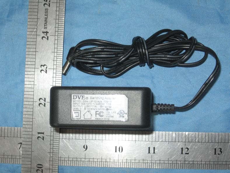
MKFARI59
May 13, 2010TRAILER MONITORING SYSTEM
Equipment Class
DSR - Part 15 Remote Control/Security Device Transceiver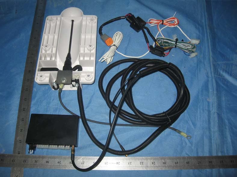
MKFARI57
May 11, 2010TRAILER MONITORING SYSTEM
Equipment Class
CYY - Communications Receiver used w/Pt 15 Transmitter
MKFARI61
May 05, 2010TRAILER MONITORING SYSTEM RX
Equipment Class
CYY - Communications Receiver used w/Pt 15 Transmitter
MKFARI62
May 02, 2010TRAILER MONITORING SYSTEM
Equipment Class
DSC - Part 15 Security/Remote Control Transmitter