MKRS512-CInstaScan Scanner, Model 512-C
Single Chip Systems Corporation
Click to zoom
Application Details
- Equipment Class
- DSS - Part 15 Spread Spectrum Transmitter
- Date of Grant
- Aug 08, 2002
- Application Purpose
- Original Equipment
- Date of Application
- Apr 15, 2002
- Equipment Note
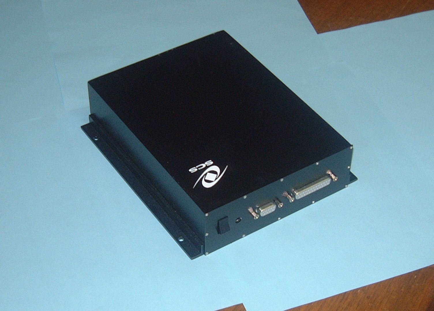
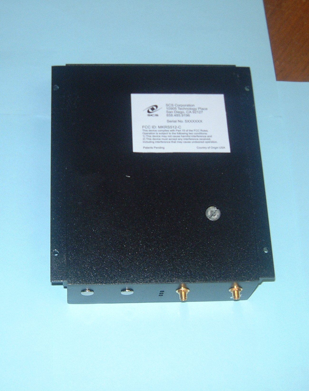
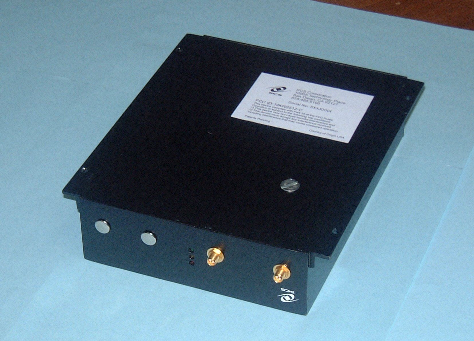
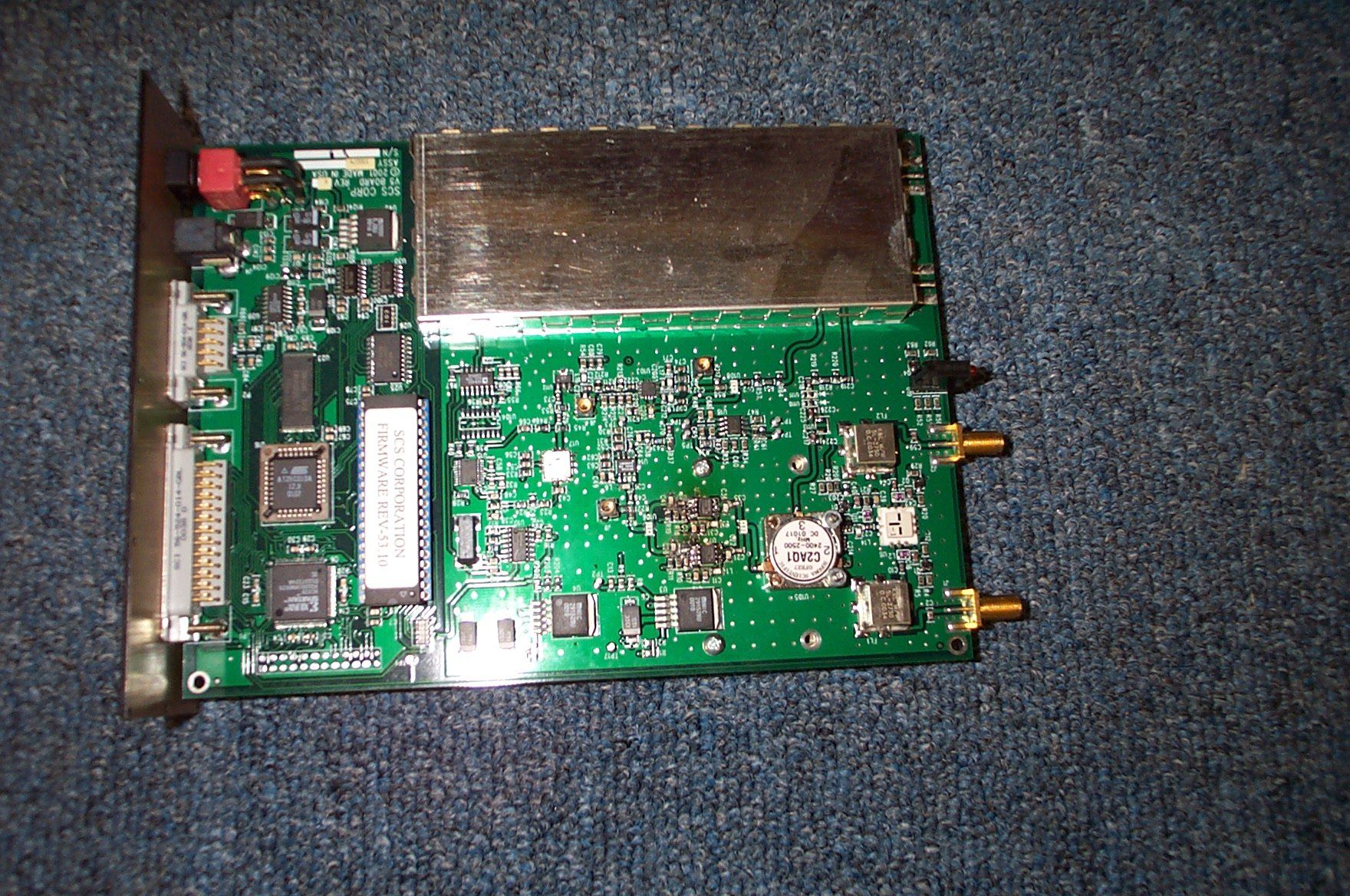
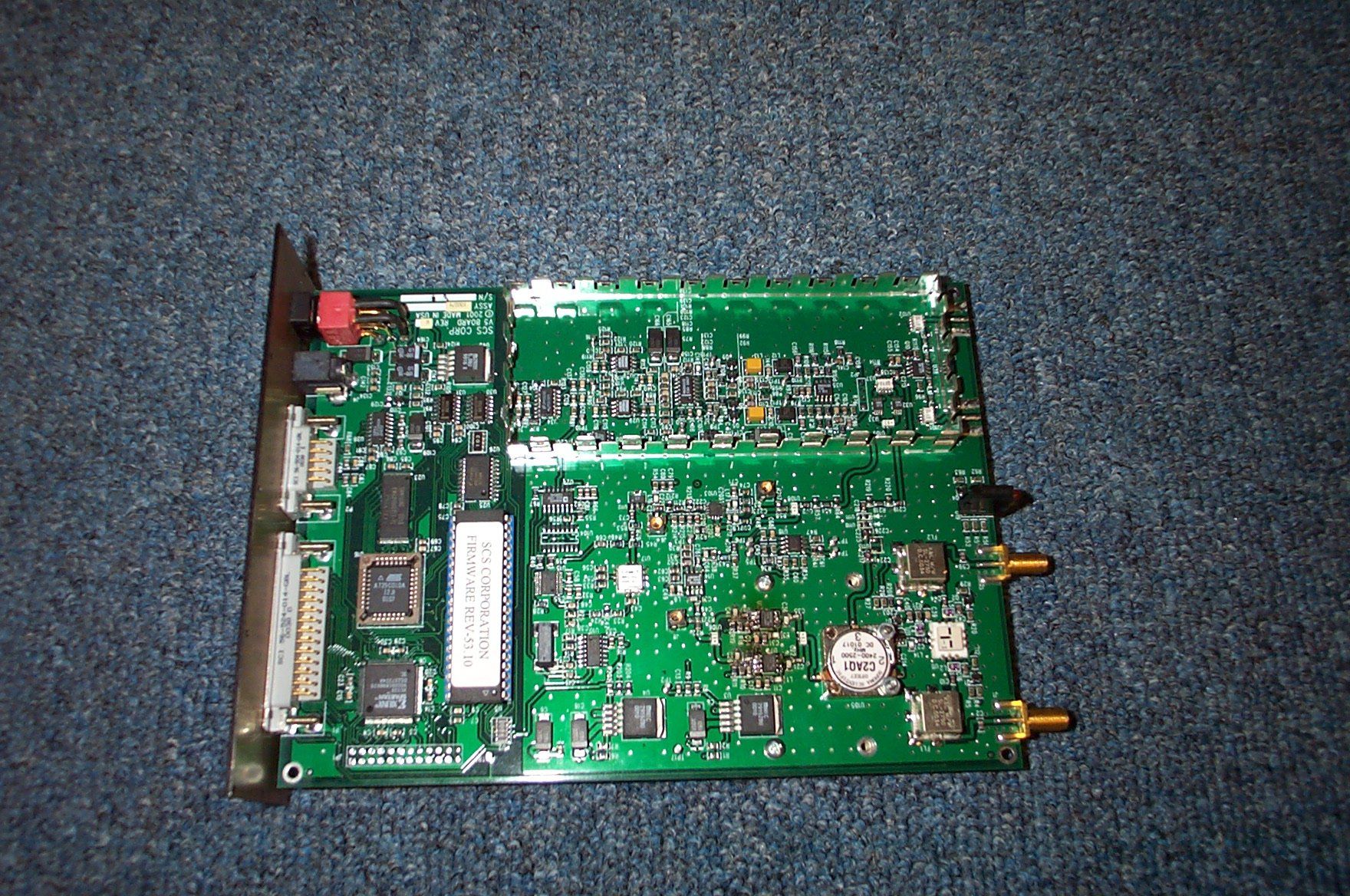
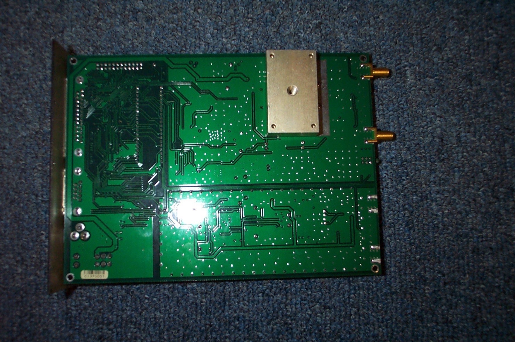
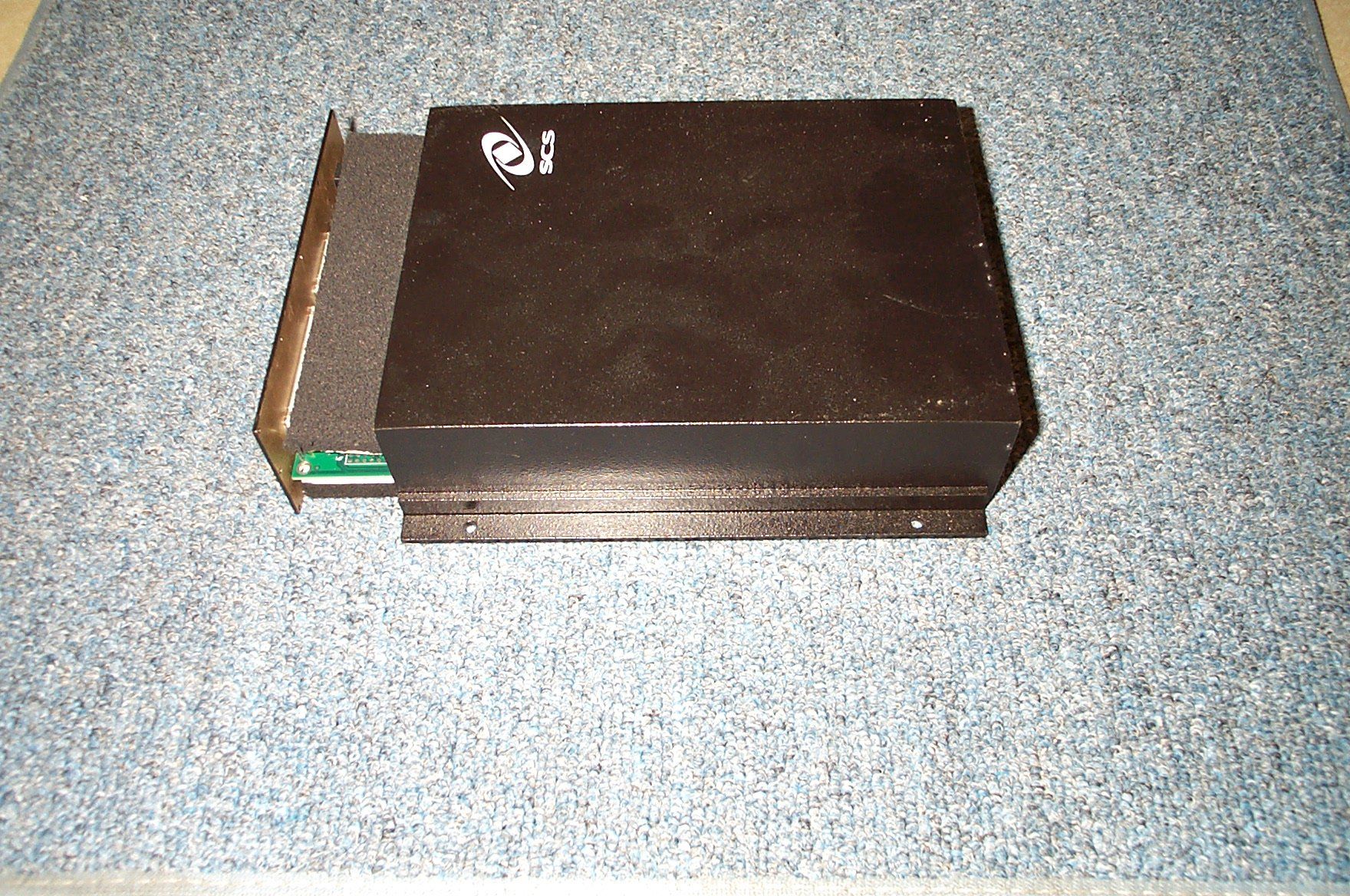
- InstaScan Scanner, Model 512-C
- Frequency Range
- 2401.00000000 - 2475.00000000
- Country
- United States
Documents & Files
Document Text
Text extracted from the exhibit documents filed with the FCC. Open a document above to read the original.
Users Manual
INSTASCAN © SCANNER MODEL S512-C Operations Manual SCS Corporation 10905 Technology Place, San Diego, CA 92127 Phone: 858-485-9196 • Fax: 858-485-0561 www.scs-corp.com • [email protected] licensed products of SCS. This Operations Manual contains proprietary information protected by copyright and this Operations Manual and all accompanying hardware, software, and documentation are copyrighted. SCS does not warrant that the hardware will work properly in all environments and applications, and makes no warranty and representation, either implied or expressed, with respect to the quality, performance, or fitness for a particular purpose. Information in this Operations Manual is subject to change without notice and does not represent a commitment on the part of SCS. SCS assumes no responsibility for incidental damage that may result do to any inaccuracies that may be contained in this Operations Manual. SCS makes no commitment to update or keep current the information in this Operations Manual, and reserves the right to make changes to this Operations Manual and/or product without notice. No part of this manual may be reproduced or transmitted in any form or by any means, electronic or mechanical, including photocopying, recording, or information storage and retrieval systems, for any purpose other than the purchaser’s personal use, without the express written permission of SCS. MS-DOS and Windows are registered trademarks of Microsoft Corporation. All other trademarks or registered trademarks listed belong to their respective owners. InstaScan and Dura-label are trademarks of SCS Corporation. Version 100837-1 Rev. A ©Copyright 2002 SCS 10905 Technology Place San Diego, CA 92127 ii iii Contents Chapter 1— Introduction.......................................................1 Advantages.....................................................................2 S512-C InstaScan Scanner................................................4 What Else You Need.........................................................5 Summary of Chapters........................................................6 Chapter 2 — Installation.......................................................7 LEDs and Connectors......................................................7 Front Panel.....................................................................8 Rear Panel....................................................................10 Scanner Installation Steps..............................................11 Connecting External Antennas........................................12 Placing the Antennas.....................................................13 Connecting to a PC Serial Port or RS-232.......................14 Connecting to an AC Outlet............................................15 Testing the Scanner Setup................................................16 Aligning the Antenna......................................................19 Installing Dura-labels......................................................20 Reading Information from your Dura-labels.......................21 Writing information to your Dura-label..............................22 Loading Your Application................................................23 Chapter 3 — RF Communications........................................24 Signal Interference........................................................25 Signal Attenuation/Reflections........................................26 Optimizing Performance................................................27 iv Chapter 4 — Troubleshooting..............................................28 Solving Problems...........................................................28 Contacting Customer Service.........................................31 Returning Your System....................................................31 Chapter 5 — Specifications.................................................33 SCS Patents...................................................................33 S512-C Scanner Specifications.........................................34 Chapter 6 — DB-25 Connector Function...............................36 Pin Assignments............................................................37 Receive Antenna Select Lines..........................................37 Transmit Antenna Select Lines.........................................38 Peripheral Inputs...........................................................38 Peripheral Outputs........................................................39 Limited Warranty...........................................................41 FCC Part 15 Compliance................................................41 Radio Frequency exposure limits.......................................42 Disclaimer.....................................................................42 1 Chapter 1Chapter 1 Chapter 1Chapter 1 Chapter 1 IntroductionIntroduction IntroductionIntroduction Introduction T he S512-C InstaScan scanner and the Dura-label radio frequency (RF) tags developed by SCS are state-of-the-art data gathering and inspection systems that combine sophisticated Interactive Identification technology in a compact form factor. This unique synergy allows our system to integrate seamlessly into — and significantly increase productivity for — a wide range of applications and environments. This system consists of the following components: A scanner that writes information to and reads information from RF tags using a read/write head (antenna). The scanner conforms to FCC Part 15 specifications and can operate with one or two externally connected antennas. Dura-label RF tags that contain information programmed by the scanner. These tags are designed to store information under extremely harsh environments without requiring a battery, and the read/write tags can store a permanent record of multiple events and transactions. Communications between the scanner and the tags are conducted using a revolutionary two-way technology that provides supe…
Text truncated - open the document above for the full version.
ID Label/Location Info
SCSCorporation 10905TechnologyPlace SanDiego,CA92127 858.485.9196 SerialNo.5XXXXXX FCCID:MKRS512-C ThisdevicecomplieswithPart15oftheFCCRules. Operationissubjecttothefollowingtwoconditions: 1)Thisdevicemaynotcauseharmfulinterferenceand 2)Thisdevicemustacceptanyinterferencereceived, includinginterferencethatmaycauseundesiredoperation. PatentsPendingCountryofOriginUSA
ID Label/Location Info
SCSCorporation 10905TechnologyPlace SanDiego,CA92127 858.485.9196 SerialNo.5XXXXXX FCCID:MKRS512-C ThisdevicecomplieswithPart15oftheFCCRules. Operationissubjecttothefollowingtwoconditions: 1)Thisdevicemaynotcauseharmfulinterferenceand 2)Thisdevicemustacceptanyinterferencereceived, includinginterferencethatmaycauseundesiredoperation. PatentsPendingCountryofOriginUSA
Operational Description
Andy Leimer FCC Application Processing Branch RE: Correspondence Reference Number 22895 FCC ID: MKRS512-C 731 Confirmation Number EA386289 Our intent was to certify a derivative product that is practically the same as the MKRS512. The difference is that the MKRS512-C discards the separate receive antennas by including a circulator. The block diagrams below illustrate. I guess I misinterpreted 2.1043(d). It states, “... If the characteristics required to be reported are not changed the abbreviated procedure of 2.933 may be used.” In fact, all of those characteristics have not changed. Given that the reportable characteristics remain the same, can we add a new product with a new FCC Identifier MKRS512-C? What is the alternative? Can we market the product with a new model number but the old FCC Identifier? You asked: (1) In the original application (FCC ID: MKRS512) do both transmit antennas transmit simultaneously? No. In neither the MKRS512 nor the proposed MKRS512-C do both transmit antennas transmit simultaneously. In both units, the RF is switched from one antenna to the other. Only one antenna radiates at a time. This allows spacial diversity for powering and communicating with passive RFID tags. (2) Submit a block diagram for the new configuration. What I have done is draw a block of the difference between the two units. In the case of the MKRS512, the output of the final amplifier section is applied to an RF switch and then to one of the transmit antennas. In the case of the MKRS512-C, the output of the final amplifier section is applied through a circulator and then to the RF switch and one of the transmit antennas. The backscattered signal from an RFID tag is routed to the receiver through another RF switch in the case of the original unit. In the case of the proposed new unit, the received signal is routed through the circulator to the receiver. If I can provide additional help or information, I am also available at 858-485-9196 x109. Regards, Gary Bann 2 1 3 Original Transmitter Section SMA 1 2 2 1 3 LP filter RF Switch Reciever SMA 1 2 SMA 1 2 SMA 1 2 RF SwitchLP filter This is a block diagram of the pertinent parts of the Original MKRS512 Original Transmitter Section Reciever LP filter SMA 1 2 RF Switch SMA 1 2 Circulator2 1 3 .. . LP filter This is the equivalent block diagram for the New MKRS12-C
Operational Description
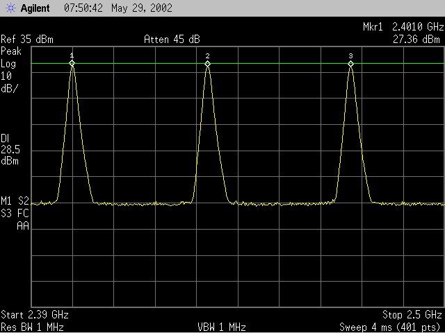
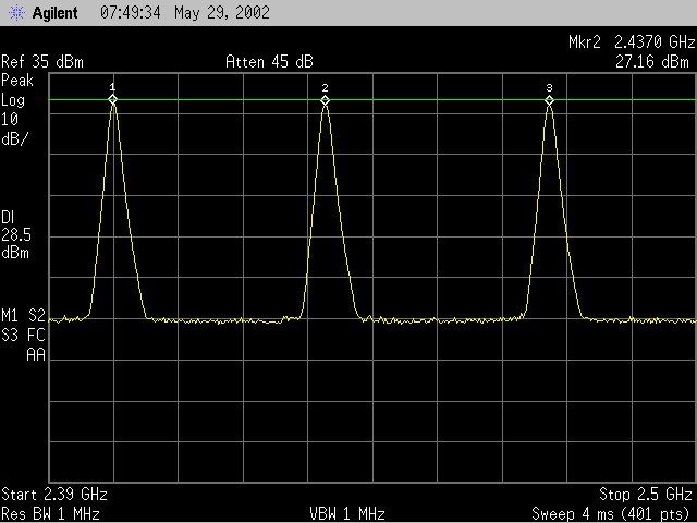
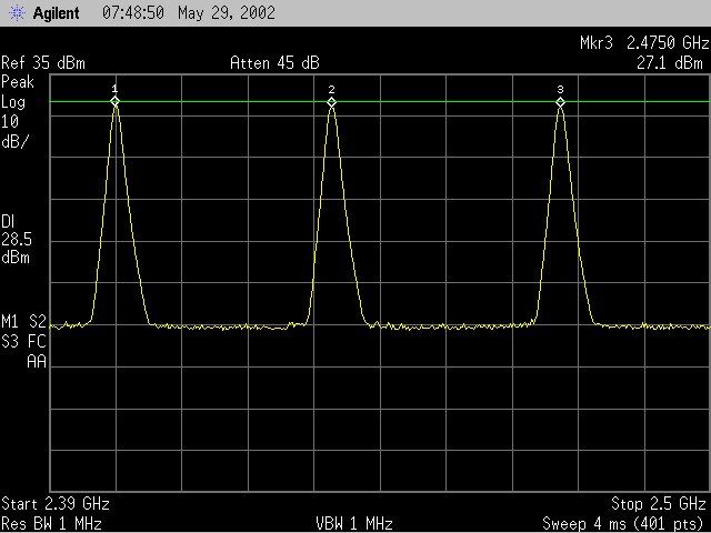
FCC ID: MKRS512-C Functional Description Purpose: This device is intended for applications in the areas of identification, verification, and inventory control. The system consists of two main parts, a reader and ID tags. The reader interrogates the tags that are attached to objects in the field created by the reader. Tags are small in size and have read/write capability. Theory of Operation: The ID tags derive their power from the RF energy of the reader signal. They are not internally powered. Signaling from reader to tag is accomplished by momentarily switching off the RF transmitter in a predetermined pattern. Signaling from tag to reader is accomplished through antenna backscatter. The tag momentarily shorts its antenna terminals together, which causes the transmitted power that was being absorbed into the tag to reflect back off its antenna. The receiver senses this reflected signal. Transmitter: The transmitter produces a phase locked CW signal that is modulated by momentarily switching off the output power. In the transmitter, the phase locked loop output is amplified and then modulated by an RF switch that is controlled by the microprocessor. The RF signal then passes through the final amplifier stage, circulator, SPDT switch, and low pass filter and ultimately is transmitted from the antenna. Receiver: The sensed backscatter signal from the antenna comes through the SPDT switch, through the circulator, to a power divider. The two signals from the power divider are quadrature down converted (to base band) using an LO tapped from the transmitter. The two base band signals are amplified and filtered, the absolute values are taken, and the two resultant signals are summed. This composite base band signal goes to a comparator circuit that provides an input signal to the microprocessor. Antenna: The MKRS512-C scanner can use up to two antennas. Only one antenna at a time can be selected to emit energy and sense the backscattered signal. Power: The power conducted to the selected active antenna is less than 28.5 dBm. With an antenna gain of 8.5 dBi, the effective isotropic radiated power is rated at less than 36 dBm (4 Watts). Modulated Signal Bandwidth: The 20dB bandwidth of the modulated signal is less than 1 MHz. Frequency Hopping Configuration: There are 75 hopping channels with center frequencies located at 1 MHz intervals starting at 2401 MHz and continuing to 2475 MHz. The hopping dwell time is 300 milliseconds. The frequencies – numbered 1 through 75 – are chosen pseudorandomly. The frequency number is modulo 75 of the contents of a 7-bit maximum length feedback shift register. Equal use of all channels per paragraph 15.247(a)(1): The linear feedback shift register (counter) operates continuously as soon as primary power is switched on. However, power is not applied to the final amplifier stage (to begin transmitting) until the scanner receives a command from the host computer. The frequency at which the scanner actually begins to transmit is therefore uniformly distributed across the 75 channels. The shift register (counter) continues to operate which guarantees a uniform distribution of restart frequencies.
RF Exposure Info
MPE Calculation for the MKRS512-C Transceiver SCS Corporation FCC ID: MKRS512-C InstaScan Scanner Table 1 of CFR47 1.1310 sets the MPE for Uncontrolled Exposure at 1mw/cm 2 for the 2.45 GHz frequency range emitted by this device. MPE = 1 mw/cm 2 = 10 W/m 2 Using the equation P d = P t G t /4πR 2 , where P d = power density in Watts per square meter = 10 W/m 2 P t = transmitted power in Watts = = .7 W G t = numerical gain of transmitting antenna = 5.6 R = distance from antenna in meters Solving for R, R= 10*4/6.5*7.π R = .177 m R = 7.0 inches The range at which the power density of the MKRS512-C InstaScan Scanner falls below 1 mw/cm 2 is 7 inches. This information will be included in the MKRS512-C Operation Manual.
RF Exposure Info
42 Radio Frequency Exposure The antennas for this device should be mounted so that nearby persons will not be within 8 inches (20 centimeters) of the antennas in order to comply with FCC adopted RF exposure limits. For more information on RF Exposure, please refer to the FCC Office of Engineering and Technology Bulletin 65, Guidelines for Human Exposure to Radiofrequency Electromagnetic Fields, available online at: http://www.fcc.gov/oet/info/documents/bulletins/ Disclaimer Operation of any radio transmitting equipment, including the Scanner, may interfere with the functionality of inadequately protected medical devices. Consult a physician or the manufacturer of the medical device if you have any questions. Other electronic equipment may also be subject to interference. SCS Support (858) 485-9196 8:00 a.m. – 5:00 p.m. PST Email – [email protected]
Schematics
55 44 33 22 11 D D C C B B A A RED YEL GRN 100273 B Schematic Diagram, Model S512 - Top Level B 15 Monday, May 20, 2002 TitleSize Document Number Rev Date: Sheet of TRANSMI TTER TRANSMI TTER DATA DCLK LE CLKCS_N THRESHHOLD TX_ON LO TXDVinGNDVCOSHDN TX_ASEL0 TXSW_OUT1TXSW_OUT2 Vcc 5V RFIN1 DIGITALDIGITAL TP6 RX_ASEL3 DATA TP5 TX_ASEL0 PER_OUT1 SYNCH_OUTTP4 RX_ASEL4 TX_ASEL3 CS_N TP3PER_OUT0 RX_ASEL5 TX_ASEL4 LE TX_ASEL1 TP0 TX_ASEL5 RX_ASEL1 RS232OUT TP2 TX_ON RS232INPBRESET TX_ASEL2 TP1 TXD_N BLANK Vin RX_ASEL0 ENV CLK GND TXD PER_OUT3 RX_ASEL2 DCLK PER_OUT2 COMPOUT TP7 PER_IN2PER_IN1 PER_IN0PER_IN3 DONE PER_OUT4PER_OUT5PER_OUT6 PER_OUT7 Vcc INIT DOUTTP8 TP9 TP10 TPSEL0 TPSEL1 BUFCOMP RECEIVERRECEIVER RFIN1 LO GND COMPOUTTHRESHHOLDBUFCOMPINRX_ASEL05V DCIN LOTHRESHHOLD Vin TXSW_OUT2TXSW_OUT1 PER_OUT1 RX_ASEL4RX_ASEL5RX_ASEL3 VCOSHDN TP0DOUT GND CS_N PER_OUT3 DATA PER_OUT0 RS232IN TXD TP7 BUFCOMPINBLANK GND PER_OUT5 TP4 TX_ASEL1TX_ASEL5 LEDCLK PER_IN3 INIT RX_ASEL0 CLKTX_ON Vin TP1 PER_OUT4 TP6TP5 TX_ASEL3PER_IN1RX_ASEL2 TXD GND TX_ASEL4TX_ASEL2 SYNCH_OUTDONE PER_IN0 BUFCOMP RX_ASEL1 RS232OUT TX_ASEL0 TP3 PBRESET TP2 PER_OUT6 BUFCOMPIN PER_IN2 TX_ON Vcc ENVBLANKTP8TP9TP10TPSEL0TPSEL1PER_OUT7 COMPOUT 5V R51200 R52200 Q3 MMBT3904 Q4MMBT3904 R624.7K R634.7K P156-524-01 4-GBL 1325122411231022 9 21 8 20 7 19 6 18 5 17 4 16 3 15 2 14 1 C1530.1UF + C16233UF C14222PF C1341000PF J2 142-470 1-801 J1 142-470 1-801 JP1 HEADER 24 123456789 101112131415161718192021222324 S1DPDT 2 31 5 64 U19564-010 0-132 12 34 56 D1C D1A D2C D2A D3C D3A C8922PF C881000PF J42.1mm C831000PF P256-504-01 4-GBL 594837261 C8422PF R6810 R50200 55 44 33 22 11 D D C C B B A A 8052 74HCT373 62864 AT29C010 74LS32 SP232EEN XCS30 (2 PER SIDE)BYPASS CAPACITORS - PLACE THESE PAIRS OF CAP ACITORS CLOSE TO POWER PIN OF DEVICE INDICATED. 74LS00 ORNAND 100273 B Schematic Diagram, Model S512 - Digital B 25 Monday, May 20, 2002 TitleSize Document Number Rev Date: Sheet of A0 A14 D7 RESET A8 D6 CLK D0 D5 A15 D6D2 A9 A15 D6 A14 A6A2 A7 D3 A11D3 A12 D2A8 D4 A15ALEA12 D2 D7 A10 A7 A2A4A7 D3 A13A14 D6 D7 D4 D6 D3 Vin A4 A0A2 D5 A11 RESET A0A5 D4 A1 A1 D0D7 D4 D7 A1A3A6 A10 D1 D0 A9A11A3 D2 RD_N A5 CLK A13 A5 D1D0 A8 D1 A10 RESET D5 A9 A3 A4 COMPOUT A12 PSEN D2 D1 D5 A6A13 D5D4D0D1D3 FLASHCTLX_PROG FLASHCE FLASHCE X_PROGDATADCLK DONE FLASHCTL RXD TXDATA COMPOUT D0D1D2D3D4D5D6D7 UPWR RAMWR RAMWRFLASHWR INTCINTAINTB INTBINTCINTAUPWR BUFCOMP Vcc Vcc Vss Vcc Vcc Vcc Vcc C14 0.1UF R95100K C29 0.1UF C129NU C15 1000PF + C147100UF C30 1000PF U2574HCT373 3478 13141718 1 11 256912151619 D0D1D2D3D4D5D6D7OCG Q0Q1Q2Q3Q4Q5Q6Q7 C23 0.1UF U58052 311918 9 12131415 12345678 39383736353433322122232425262728171629301110 EA/VPX1X2RESETINT0INT1T0T1P1.0/T2P1.1/T2XP1.2P1.3P1.4P1.5P1.6P1.7 P0.0P0.1P0.2P0.3P0.4P0.5P0.6P0.7P2.0P2.1P2.2P2.3P2.4P2.5P2.6P2.7 RD WR PSEN ALE/P TXD RXD C1330.01UF C930.1UF R91100K C1020.1UF C1320.1UF C900.1UF C95 1000PF C1640.1UF C101 0.1UF U28SP232EEN 11 14 13 12 1310 7 8 9 45 26 T1 IN T1 OUT R1 IN R1 OUT C1+ C1- T2 IN T2 OUT R2 IN R2 OUT C2+ C2- V+V- C1100.1UF R1241K C7 0.1UF + C10933UF C9 1000PF U26 Resistor Array 10 12346789 Vcc R1R2R3R4R5R6R7R8 C78 0.1UF C75 1000PF C85 0.1UF C86 1000PF C69 0.1UF C67 1000PF C94 0.1UF R105100K C100 1000PF U16 AT29C0 10_J 1314151718192021 121110 98765 27262325 4 2829 32 222431 I/O0I/O1I/O2I/O3I/O4I/O5I/O6I/O7 A0A1A2A3A4A5A6A7A8A9A10A11A12A13A14A15A16CE OEWE C91 0.1UF Q7 MMBT3904 C87 1000PF U40 MIC29201 2 4 3 5 1 IN OUT GND SHDN ER U6 X C S30 23456789 1014 15 16 78798081 2127 2931333435 39 434445464748535455565758 99 732428 3260616265666768695250727490919293 303682838485 1718199495 CLKAD0AD1AD2AD3AD4AD5AD6AD7RD INT CS PER_OUT0PER_OUT1PER_OUT2PER_OUT3 RESETWR BLANK ENVTXD TXD_N TX_ON RXD RX_ASEL0RX_ASEL1RX_ASEL2RX_ASEL3RX_ASEL4RX_ASEL5 TX_ASEL0TX_ASEL1TX_ASEL2TX_ASEL3TX_ASEL4TX_ASEL5 ALE DOUT MODE HDC SYNCH_OUTTP0TP1TP2TP3TP4TP5TP6TP7PROGRAMDONEDINCCLKPER_IN0PER_IN1PER_IN2PER_IN3 HDC INIT PER_OUT4PER_OUT5PER_OUT6PER_OUT7 TP8TP9TP10TPSEL0TPSEL1 & U3174LS00 12459 101213 36811 C3 0.1UF U23 62864 2019181716151413 32 31 1 12 4 11 75 3230 6 2122232526272829910 A0A1A2A3A4A5A6A7A8A9A10A11A12A13A14A15WE OECS1CS2 D0D1D2D3D4D5D6D7 NCNC 1 U3074LS32 12459 101213 36811 C4 1000PF U2 Resistor Array 10 1 2 3 4 6 7 8 9 Vcc R1 R2 R3 R4 R5 R6 R7 R8 C20 1000PF + C161100UF TP6 RX_ASEL3 DATA TP5 TX_ASEL0PER_OUT1 SYNCH_OUT TP4 RX_ASEL4TX_ASEL3 CS_N TP3 PER_OUT0RX_ASEL5TX_ASEL4 LE TX_ASEL1 TP0 TX_ASEL5RX_ASEL1 TP2 TX_ON PBRESET TX_ASEL2 TP1 TXD_NBLANK Vin RX_ASEL0ENV CLK GND TXDPER_OUT3RX_ASEL2 DCLK PER_OUT2 COMPOUT TP7 PER_IN2PER_IN1PER_IN0 PER_IN3 DONE PER_OUT5PER_OUT4PER_OUT7PER_OUT6 RS232OUT RS232IN Vcc INITDOUT TP8TP9 TP10 TPSEL0 TPSEL1 BUFCOMP 55 44 33 22 11 D D C C B B A A NOTES:1. The "LO" net line must be 50 ohm to split, at split Wilkinson splitter must be 70 ohm for 1/4 wavelength to resistor. After resistor, line is 50 ohm and must be exactly same length to from each side of resistor to each mixer. 2. The line leng ths for net names "RFI" and "RFQ" must be exactly the same. 3. The line type for net names "LOAD", "RFI", "RFQ", "RFIN", "RFIN1", "RFIN2", "RF1", and "RF2" must be 50 ohm microstrip at 2.45 GHz. 100273 B Schematic Diagram, Model S512 - Receiver B 35 Monday, May 20, 2002 TitleSize Document Number Rev Date: Sheet of LOGQ LOGREFQ OUT2Q LOI RFQ RFI LOAD LOGI IFQ LOGREFI OUT2I V2 V4 V3 OUT1IOUT1Q IFI RFINB V1 Vgref V1V2 V1 V3V4 LOQ LO RFIN1 V1V2 LOGOUTQ LOGOUTI Va Vg Vg Vg Vg Vg Vg Vg Va Vg Vg Vg Vg Vg Vg Vg Vg Vg Vg Vg Vg Vg Vg Vg Va Va Vg Vg Vg C11233PF R6951 R991K C107 820PF R108 51 C1500.33UF U37LDC30B030 GC2500 12345 678910 INGNDGNDLOADGND OUT90 GNDGND OUT0 GND C10533PF R77 51 R112 100 R11451 R7810K C149 820PF R7151 R7251 C14533PF L1510UH C97 2200PF C1031UF + C167 33UF C1221UF C1040.01UF R10110K C1310.01UF C1211UF R7610 C1181UF C1200.01UF + C16533UF C152 1UF C1230.01UF R79470 +- U36CMAX4020 10 9 8 411 C151 0.01UF R9710 C98150PF C146 0.01UF R98470 R854.7 L10180UH C13822PF0603 +- U36BMAX4020 56 7 411 R884.7 L1182UH R…
Text truncated - open the document above for the full version.
Test Report
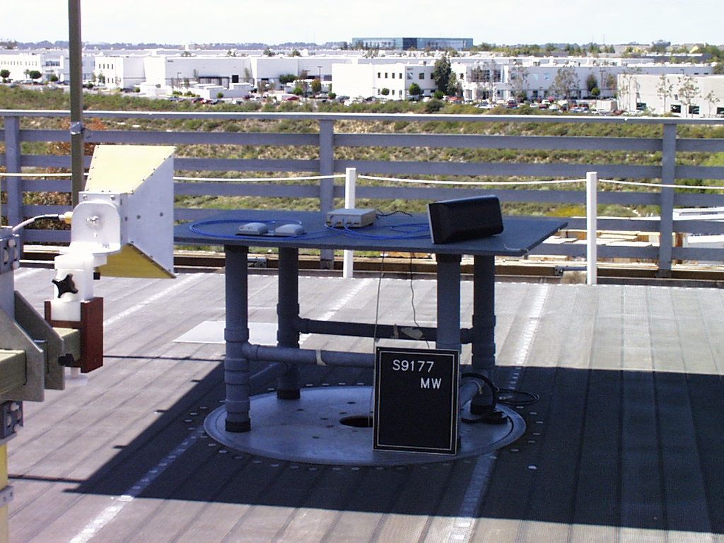
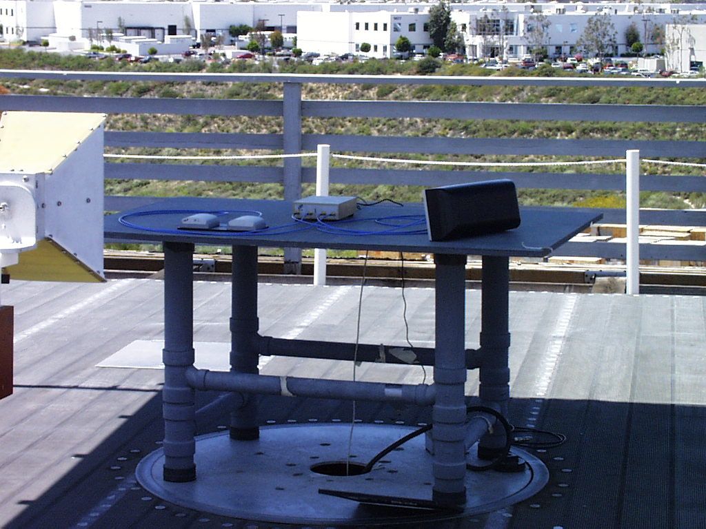
Report No. 9177-08 (FCC ID: MK4S512) Page 1 of 28 Rev.No 1.0 MEASUREMENT AND TECHNICAL REPORT SINGLE CHIP SYSTEMS DATE: 05 May 1999 This Report Concerns: Original Grant: XClass II Change: Equipment Type: InstaScan Scanner, Model S512, S/N 00002 Transition Rules Request per 15.37? Yes:*No: (*) FCC Part 15, Paragraph 15.247(a)(b)(c ) Report Prepared by: TÜV PRODUCT SERVICE 10040 Mesa Rim Road San Diego, CA 92121-2912 Phone: 619 546 3999 Fax: 619 546 0364 Report No. 9177-08 (FCC ID: MK4S512) Page 2 of 28 Rev.No 1.0 TABLE OF CONTENTS Pages 1 GENERAL INFORMATION 4 1.1Product Description4 1.2Test Methodology5 1.3Test Facility5 2 SYSTEM TEST CONFIGURATION 9 3.1Justification9 3.2EUT Exercise Software9 3.3Special Accessories9 3.4Equipment Modifications9 3.5Configuration of Tested System9 Figure 3.1Configuration of Tested System9 3 TEST REPORT 4CONDUCTED MEASUREMENT 11 CONDUCTED MEASUREMENT EQUIPMENT/TEST SETUP/DATA12 5 RADIATED MEASUREMENT ? RADIATED MEASUREMENT EQUIPMENT/TEST SETUP/DATA ? 6FIELD STRENGTH CALCULATION 7GENERAL SUMMARY Report No. 9177-08 (FCC ID: MK4S512) Page 3 of 28 Rev.No 1.0 1 GENERAL INFORMATION 1.1Product Description InstaScan Scanner, Model S512, S/N 00002 The EUT is a Transceiver for RFID purposes, designed to operate under FCC part 15.247 rules in the 2.4 to 2.483 GHz ISM band. Equipment Specifications: Frequency Range: 2401-2475 MHz; Rated RF Output Power: 0.70 Watts Frequency Tolerance: ±100 ppm Emissions Designator: 714KK1D Micro. Model No.: 80C52 1.1.1 Components of EUT (List each one separately. Add attachment if necessary. NOT TO INCLUDE PERIPHERALS.) DescriptionModel NumberSerial NumberFCC ID Number InstaScan ScannerS51200002 Power SupplyN2UFSW CSC15-1000 PS7520AWP5 4850 9632 Dual Antenna100157-1 100158-1 00001 1.2 Operating modes: (list and describe) The scanner operates in one of 2 modes. Transmit from one antenna, or alternate transmission from 2 antennas at a 50% duty cycle. Report No. 9177-08 (FCC ID: MK4S512) Page 4 of 28 Rev.No 1.0 1.3 EUT I/O Ports and Cables: 1.3.1 I/O Cables (Add attachment if necessary.) CONNECTION: DC Power SHIELD: none CONNECTORS: 2.1mm power connector TERMINATION TYPE: none LENGTH: 6 ft. REMOVABLE: yes CONNECTION: RS-232 SHIELD: none CONNECTORS: DB-9F TERMINATION TYPE: none LENGTH: 6 to 20 ft REMOVABLE: yes CONNECTION: RF Transmit Port 1 and Port 2 SHIELD: coax cable CONNECTORS: Currently SMA, Reverse polarity SMA in production TERMINATION TYPE: Coax shield to SMA connector LENGTH: 6 ft. REMOVABLE: yes CONNECTION: RF Receive Port 1 and Port 2 SHIELD: coax cable CONNECTORS: Currently SMA, Reverse polarity SMA in production TERMINATION TYPE: Coax shield to SMA connector LENGTH: 6 ft. REMOVABLE: yes Report No. 9177-08 (FCC ID: MK4S512) Page 5 of 28 Rev.No 1.0 1.3.2 Power Cords (Add attachment if necessary.) UNIT: N2UFSW MANUFACTURER: Egston SHIELDED: no LENGTH: 6 ft. UNIT: CSC15-1000 MANUFACTURER: Cortech SHIELDED: no LENGTH: 6 ft. UNIT: PS7520AWPS MANUFACTURER: Sceptre SHIELDED: no LENGTH: 6 ft. 1.3.3 Power requirements: *Note: European power is typically 230 VAC 50Hz or 400 VAC 50Hz, single and three phase, respectively. FCC requires testing to be performed at typical US power ratings at 60Hz. 230 VAC 50Hz -- single phase Amps 400 VAC 50Hz -- three phase Amps per phase X 120 VAC 60Hz -- single phase 0.5 Amps VDC Amps Battery: VDC Expected life: Hours Other: (describe) Report No. 9177-08 (FCC ID: MK4S512) Page 6 of 28 Rev.No 1.0 1.4 Oscillator Frequencies FrequencyEUT LocationDescription of use 20 MHzon PCBclock for microprocessor 1.5 Power Supply DescriptionManufacturerModel #Serial #Switching frequency or linear Wall mount 7.5 V, 2.0 AEgstonN2UFSW4850 Wall mount 7.5 V, 2.0 ACortechCSC15-1000100 KHz Wall mount 7.5 V, 2.0 ASceptrePS7520AWP59632 1.6 Power Line Filters ManufacturerModel #QtyLOCATION ON EUT Metuchen Capacitors56-504-014-GBL1Housing Metuchen Capacitors56-524-014-GBL1Housing K&LSL-27502Housing 1.7 Critical EMI Components (Capacitors, ferrites, etc.) DescriptionManufacturerPart # or valueQtyLOCATION ON EUT 1.8 Description of Enclosure: (including Gasketing, Coatings, Bonding, etc.) Aluminum housing comprised of a 5 sided box with a screw-on face plate. Report No. 9177-08 (FCC ID: MK4S512) Page 7 of 28 Rev.No 1.0 1.9 Interfacing and/or Simulators Peripheral Equipment (Please provide a complete description of all peripherals to be used during testing, please note that all I/O ports must be appropriately loaded) DESCRIPTION: Laptop Computer MANUFACTURER: Compaq MODEL NUMBER: 1210 Presario SERIAL NUMBER: FCC ID: 1.10 System Configuration Block Diagram RF COAX CABLE S512 (EUT) LAPTOP PC RS-232 TX ANTENNA POWER SUPPLY TX PORT 1 RF COAX CABLE RX ANTENNARX PORT 1 RF COAX CABLE TX ANTENNATX PORT 2 RF COAX CABLE RX ANTENNARX PORT 2 7.5 VDC Report No. 9177-08 (FCC ID: MK4S512) Page 8 of 28 Rev.No 1.0 1.11Test Methodology Purpose of Test:To demonstrate compliance with the ANSI C63.4 setup. Test Performed:X1. Conducted Emissions, FCC Part 15, Paragraph 15.247(a)(b)(c ) 2. Radiated Emissions EN55022: 1992 Class B limit, 30 - 1,000 MHz, 10 meters X3. Radiated Emission per FCC Part 15, Paragraph 15.247(c ) 4. Engineering evaluations Both Conducted and radiated testing were performed according to the procedures in FCC/ANSI C63.4 and CSA 108.8 - M1983. Radiated testing was performed at an antenna-to-EUT distance of 3 meters (1 - 10 GHz). 1.12Test Facility The open area test site and conducted measurement data were tested by: TÜV PRODUCT SERVICE 10040 Mesa Rim Road San Diego, CA 92121-2912 Phone: 619 546 3999 Fax: 619 546 0364 The Test Site Data and performance comply with ANSI 63.4 and are registered with the FCC, 7435 Oakland Mills Rd, Columbia Maryland 21046. All Measurement Data is acquired according to the content of FCC Measurement Procedure and ANSI C63.4, unless supplemented with additional requirements as noted in the test report. Report No. 9177-08 (FCC ID: MK4S512) Page 9 of 28 Rev.No 1.0 2.SYSTEM TEST CONFIGURATION 2.1Justification T…
Text truncated - open the document above for the full version.
Test Report
Report No. 0045-08 (FCC ID: MKRS512) Page 1 of 25 Rev.No 1.0 MEASUREMENT AND TECHNICAL REPORT SINGLE CHIP SYSTEMS 10905 Technology Place San Diego, CA 92127 DATE: 28 January 2000 This Report Concerns:Original Grant:Class II Change: X Equipment Type:InstaScan Scanner, Model S512, S/N 00002 Transition Rules Request per 15.37?Yes:*No: (*) FCC Part 15, Paragraph 15.247(a)(b)(c ) Report Prepared by: TÜV PRODUCT SERVICE 10040 Mesa Rim Road San Diego, CA 92121-2912 Phone: 619 546 3999 Fax: 619 546 0364 Report No. 0045-08 (FCC ID: MKRS512) Page 2 of 25 Rev.No 1.0 TABLE OF CONTENTS Pages 1 GENERAL INFORMATION3 1.1Product Description3 1.2Test Methodology7 1.3Test Facility7 2 SYSTEM TEST CONFIGURATION7 3.1Justification7 3.2EUT Exercise Software7 3.3Special Accessories7 3.4Equipment Modifications7 3.5Configuration of Tested System7 3 TEST REPORT8 RADIATED MEASUREMENT8 RADIATED MEASUREMENT EQUIPMENT/TEST SETUP/DATA 8 FIELD STRENGTH CALCULATION11 CONDUCTED MEASUREMENT14 CONDUCTED MEASUREMENT EQUIPMENT/TEST SETUP/DATA 15 4GENERAL SUMMARY25 Report No. 0045-08 (FCC ID: MKRS512) Page 3 of 25 Rev.No 1.0 1 GENERAL INFORMATION 1.1Product Description InstaScan Scanner, Model S512, S/N 00002 The EUT is a Transceiver for RFID purposes, designed to operate under FCC part 15.247 rules in the 2.4 to 2.483 GHz ISM band. Equipment Specifications: Frequency Range: 2401-2475 MHz; Rated RF Output Power: 0.70 Watts Frequency Tolerance: ±100 ppm Emissions Designator: 714KK1D Micro. Model No.: 80C52 1.1.1 Components of EUT (List each one separately. Add attachment if necessary. NOT TO INCLUDE PERIPHERALS.) DescriptionModel NumberSerial NumberFCC ID Number InstaScan ScannerS51200002MKRS512 Power SupplyN2UFS7.5V2A4850-- Dual Antenna100157-1 100158-1 00001-- 1.2 Operating modes: The scanner operates in one of 2 modes. Transmit from one antenna, or alternate transmission from 2 antennas at a 50% duty cycle. Report No. 0045-08 (FCC ID: MKRS512) Page 4 of 25 Rev.No 1.0 1.3 EUT I/O Ports and Cables: 1.3.1 I/O Cables (Add attachment if necessary.) CONNECTION: DC Power SHIELD: none CONNECTORS: 2.1mm power connector TERMINATION TYPE: none LENGTH: 6 ft. REMOVABLE: yes CONNECTION: RS-232 SHIELD: none CONNECTORS: DB-9F TERMINATION TYPE: none LENGTH: 6 to 20 ft REMOVABLE: yes CONNECTION: RF Transmit Port 1 and Port 2 SHIELD: coax cable CONNECTORS: Reverse polarity SMA in production TERMINATION TYPE: Coax shield to SMA connector LENGTH: 6 ft. REMOVABLE: yes CONNECTION: RF Receive Port 1 and Port 2 SHIELD: coax cable CONNECTORS: Reverse polarity SMA in production TERMINATION TYPE: Coax shield to SMA connector LENGTH: 6 ft. REMOVABLE: yes 1.3.2 Power Cords UNIT: N2UFS7.5V2A MANUFACTURER: Power Components International SHIELDED: no LENGTH: 6 ft. Report No. 0045-08 (FCC ID: MKRS512) Page 5 of 25 Rev.No 1.0 1.3.3 Power requirements: X 120 VAC 60Hz -- single phase 0.5 Amps 1.4 Oscillator Frequencies FrequencyEUT LocationDescription of use 20 MHzon PCBclock for microprocessor 1.5 Power Supply DescriptionManufacturerModel #Serial #Switching frequency or linear Wall mount 7.5 V, 2.0 APower Components International N2UFS7.5V2A4850-- 1.6 Power Line Filters ManufacturerModel #QtyLOCATION ON EUT Metuchen Capacitors56-504-014-GBL1Housing Metuchen Capacitors56-524-014-GBL1Housing K&LSL-27502Housing 1.7 Critical EMI Components (Capacitors, ferrites, etc.) DescriptionManufacturerPart # or valueQtyLOCATION ON EUT L14 C27 Samsung Toko 0.5 pF 1.5 nH 1 1 Between coupler and SPDT switch Between coupler and SPDT switch 1.8 Description of Enclosure: (including Gasketing, Coatings, Bonding, etc.) Aluminum housing comprised of a 5 sided box with a screw-on face plate. 1.9 Interfacing and/or Simulators Peripheral Equipment DESCRIPTION:Laptop Computer MANUFACTURER:Compaq MODEL NUMBER:1210 Presario SERIAL NUMBER: -- FCC ID: -- Report No. 0045-08 (FCC ID: MKRS512) Page 6 of 25 Rev.No 1.0 1.10 System Configuration Block Diagram RF COAX CABLE S512 (EUT) LAPTOP PC RS-232 TX ANTENNA POWER SUPPLY TX PORT 1 RF COAX CABLE RX ANTENNARX PORT 1 RF COAX CABLE TX ANTENNATX PORT 2 RF COAX CABLE RX ANTENNARX PORT 2 7.5 VDC Report No. 0045-08 (FCC ID: MKRS512) Page 7…
Text truncated - open the document above for the full version.
Contact Information
Applicant
Bruce B Roesner(Chief Technical Officer)
Technical Contact
SCS CorporationGary Bann
[email protected]858-485-9196
10905 Technology Place · San Diego, California · United States
Non-Technical Contact
SCS CorporationJim Kruest
[email protected]858-485-9196
Test Firm
TUV AmericaJames Owen
Technical Specifications
| # | Rule Parts | Frequency Range | Power Output |
|---|---|---|---|
| 1 | 15C | 2.40 GHz - 2.48 GHz | 700.00 mW |
Other Applications from Single Chip Systems Corporation

MKRS556-EP
Mar 11, 2001RFID Transciever
Equipment Class
TNB - Licensed Non-Broadcast Station Transmitter
MKRU519
Mar 05, 20019 Antenna InstaScan Scanner, Model U519
Equipment Class
DSS - Part 15 Spread Spectrum Transmitter
MKRS556
May 22, 2000Model S556 Scanner
Equipment Class
TNB - Licensed Non-Broadcast Station Transmitter
MKRS516
May 07, 20006 Antenna InstaScan Scanner
Equipment Class
DSS - Part 15 Spread Spectrum Transmitter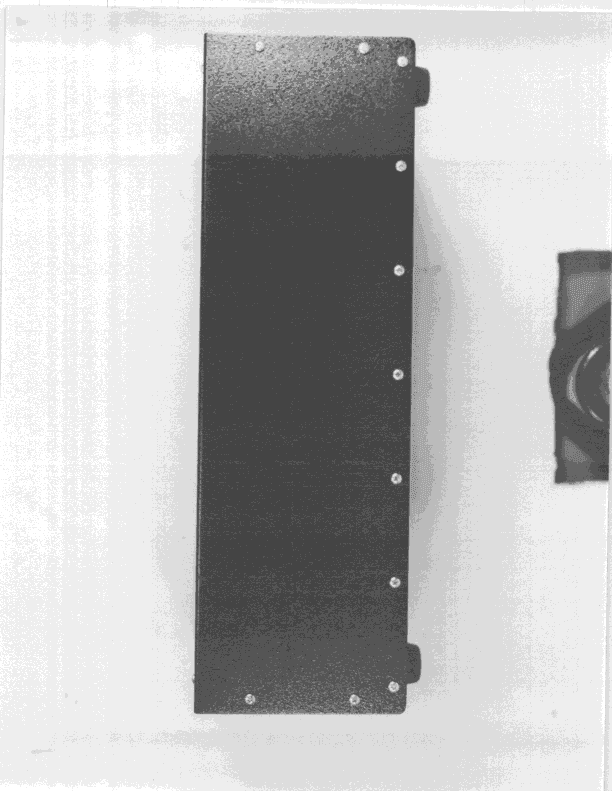
MKRS416
Jul 26, 1999DSS - Part 15 Spread Spectrum Transmitter
Equipment Class
DSS - Part 15 Spread Spectrum Transmitter