MKRS5166 Antenna InstaScan Scanner
Single Chip Systems Corporation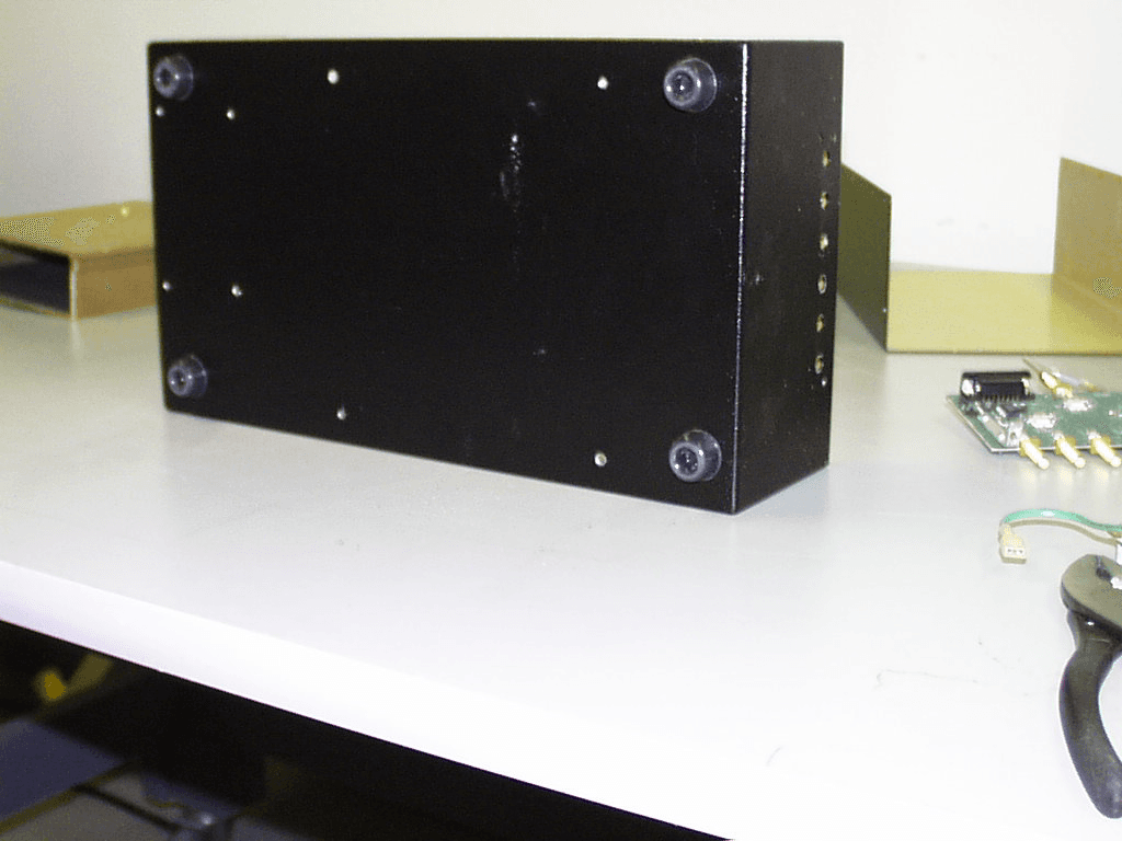
Click to zoom
Application Details
- Equipment Class
- DSS - Part 15 Spread Spectrum Transmitter
- Date of Grant
- May 07, 2000
- Application Purpose
- Original Equipment
- Date of Application
- Apr 10, 2000
- Equipment Note
- 6 Antenna InstaScan Scanner
- Frequency Range
- 2401.00000000 - 2475.00000000
- Country
- United States
Documents & Files
Document Text
Text extracted from the exhibit documents filed with the FCC. Open a document above to read the original.
Attestation Statements
FCC ID: MKR S516 Page 1 of 1 Rev.No 1.0 SIGNATURE PAGE GENERAL REMARKS: SUMMARY: All tests according to United States Standard 47 CFR Part 15, Paragraph 15.207(a); 15.209(a); 15.247(a)(b)( c) n- Performed o - Not Performed The Equipment Under Test n- Fulfills the general approval requirements to United States Standard 47 CFR Part 15, Paragraph 15.207(a); 15.209(a); 15.247(a)(b)( c) o - Does not fulfill the general approval requirements cited on page 1. - TÜV PRODUCT SERVICE, INC. - Responsible Engineer: Mary Washington (EMC Engineer)
Test Report
Report No. 0136-08 (FCC ID: MKR S516) Page 1 of 36 Rev.No 1.0 MEASUREMENT AND TECHNICAL REPORT SINGLE CHIP SYSTEMS 10905 Technology Place San Diego, CA 92127 DATE: 11 April 2000 This Report Concerns:Original Grant: XClass II Change: Equipment Type:6 Antenna InstaScan Scanner, Model S516 Transition Rules Request per 15.37?Yes:*No: (*) FCC Part 15, Paragraph 15.207(b); 15.209(b);15.247(a)(1)(ii)(b)(c) Report Prepared by: TÜV PRODUCT SERVICE 10040 Mesa Rim Road San Diego, CA 92121-2912 Phone: 619 546 3999 Fax: 619 546 0364 Report No. 0136-08 (FCC ID: MKR S516) Page 2 of 36 Rev.No 1.0 TABLE OF CONTENTS Pages 1 GENERAL INFORMATION3 1.1Product Description3 1.2Test Methodology11 1.3Test Facility11 2 SYSTEM TEST CONFIGURATION11 3.1Justification11 3.2EUT Exercise Software11 3.3Special Accessories11 3.4Equipment Modifications11 3.5Configuration of Tested System11 3 TEST REPORT12 RADIATED MEASUREMENT12 RADIATED MEASUREMENT EQUIPMENT/TEST SETUP/DATA 12 FIELD STRENGTH CALCULATION13 CONDUCTED MEASUREMENT17 CONDUCTED MEASUREMENT EQUIPMENT/TEST SETUP/DATA 17 4GENERAL SUMMARY35 Report No. 0136-08 (FCC ID: MKR S516) Page 3 of 36 Rev.No 1.0 1 GENERAL INFORMATION 1.1Product Description 6 Antenna InstaScan Scanner, Model S516, S/N 5160002 Report No. 0136-08 (FCC ID: MKR S516) Page 10 of 36 Rev.No 1.0 Direct sequency spread spectrum transmitters: N/A Scanning receivers: N/A Description of compliance of the associated receiver or receivers: The receiver employs a homodyne architecture. The LO signal in the receiver is split from the transmitted RF early in the transmitter chain, and is therefore, at the same frequency. The received signal is mixed with the LO signal to create a baseband IF. The IF signal is filtered to 1 MHz, which matches the hopping channel bandwidth. Certification of transmitters operating within the 59 to 64 GHz band: N/A Report No. 0136-08 (FCC ID: MKR S516) Page 11 of 36 Rev.No 1.0 1.11Test Methodology Purpose of Test:To demonstrate compliance with the ANSI C63.4 setup. Test Performed:X1. Conducted Emissions, FCC Part 15, Paragraph 15.207(a); 15.247(a)(b)(c ) 2. Radiated Emissions EN55022: 1992 Class B limit, 30 - 1,000 MHz, 10 meters X3. Radiated Emission per FCC Part 15, Paragraph 15.209(a); 15.247(c ) 4. Engineering evaluations Both Conducted and radiated testing were performed according to the procedures in FCC/ANSI C63.4 and CSA 108.8 - M1983. Radiated testing was performed at an antenna-to-EUT distance of 3 meters (1 - 10 GHz). 1.12Test Facility The open area test site and conducted measurement data were tested by: TÜV PRODUCT SERVICE 10040 Mesa Rim Road San Diego, CA 92121-2912 Phone: 619 546 3999 Fax: 619 546 0364 The Test Site Data and performance comply with ANSI 63.4 and are registered with the FCC, 7435 Oakland Mills Rd, Columbia Maryland 21046. All Measurement Data is acquired according to the content of FCC Measurement Procedure and ANSI C63.4, unless supplemented with additional requirements as noted in the test report. 2.SYSTEM TEST CONFIGURATION 2.1Justification The EUT InstaScan Scanner was initially tested for FCC emission in the following configuration: See photos and test setup drawings. 2.2EUT Exercise Software None 2.3Special Accessories None 2.4Modification None 2.5Configuration of Tested System See photos and test setup drawings. Report No. 0136-08 (FCC ID: MKR S516) Page 12 of 36 Rev.No 1.0 3TEST REPORT 3.1Emissions Test Conditions: RADIATED EMISSIONS, FCC Part 15, Paragraphs 15.209(a); 15.247(c ) The RADIATED EMISSIONS measurements were performed at the following test location : o - Test not applicable n - Roof (Small Open Area Test Site) n - Canyon #2 (3- and 10-meter Open Area Test Site), Carroll Canyon, San Diego Testing was performed at a test distance of: n- 3 meters Test Equipment Used : Model No.Prop. No.DescriptionManufacturerSerial No.Cal Date 3115453Antenna, Double Ridge GuideEMCO9412-436310/00 8566B720Spectrum AnalyzerHewlett Packard21150084203/01 8566B721Spectrum Analyzer DisplayHewlett Packard2112A0218 5 03/01 AFD3-0208-40-ST367Pre-Amplifier (30 dB gain), 2 to 8 GHz Miteq, Inc.15538204/00* AFD4-08001800-70- 10P-4 368Pre-Amplifier (22 dB gain), 8 to 18 GHz Miteq, Inc.15538204/00* AA-190-10.00.0656High Frequency CableUnited Microwave Pro --04/00* AA-190-30.00.0664High Frequency CableUnited Microwave Pro --04/00* LPB2520/A739LPBAntenna Research117004/00* CCA-7178CISPR AdapterEaton0106-0807502/01 Remarks:(*) Verified Report No. 0136-08 (FCC ID: MKR S516) Page 13 of 36 Rev.No 1.0 Field Strength Calculation If a preamplifier was used during the Radiated Emission Testing, it is required that the amplifier gain must be subtracted from the Spectrum Analyzer (Meter) Reading. In addition, a correction factor for the antenna , cable used and a distance factor, if any, must be applied to the Meter Reading before a true field strength reading can be obtained. In the automatic measurement, these considerations are automatically presented as a part of the print out. In the case of manual measurements and for greater efficiency and convenience, instead of using these correlation factors for each meter reading, the specification limit was modified to reflect these correlation factors at each frequency value so that the meter readings can be compared directly to the modified specification limit. This modified specification limit is referred to as the "Corrected Meter Reading Limit" or simply the CMRL, which is the actual field strength present at the antenna. The quantity can be derived in the following manner: Corrected Meter Reading Limit (CMRL) = SAR + AF + CL - AG - DC Where, SAR = Spectrum Analyzer Reading AF = Antenna Factor CL = Cable Loss AG = Amplifier Gain (if any) DC = Distance Correction (if any) Assume the following situation: A meter reading of 29.4 dBuV was obtained from a Class A computing device measured at 83 MHz. Assume an antenna factor of 9.2 dB, a cable loss of 1.4 dB and amplifier gain of 20.0 dB at 83 MHz. The final field strength would be det…
Text truncated - open the document above for the full version.
Test Setup Photos
FCC ID: MKR S516 Photograph of Test Setup (15.209(a) FCC ID: MKR S516 Photograph of Test Setup (15.209(a) FCC ID: MKR S516 Photograph of Test Setup (15.247(c) FCC ID: MKR S516 Photograph of Test Setup (15.247(c) FCC ID: MKR S516 EUT RF 10 dB Attenuator Spectrum Analyzer & Spectrum Analyzer Display Direct Connect Test Setup, Part 15, Paragraph 15.247(a)(b)(c) FCC ID: MKR S516 Photograph of Test Setup FCC 15.207(a) FCC ID: MKR S516 Photograph of Test Setup FCC 15.207(a) FCC ID: MKR S516
Contact Information
Applicant
Bruce B Roesner(Chief Technical Officer)
Technical Contact
TUV Product ServiceMary T Washington
[email protected]858 546 3999
10040 Mesa Rim Road · San Diego, California · United States
Non-Technical Contact
TUV Product ServiceJudy F Evans
[email protected]858 546 3999
Test Firm
TUV AmericaJames Owen
Technical Specifications
| # | Rule Parts | Frequency Range | Power Output | Tolerance |
|---|---|---|---|---|
| 1 | 15C | 2.40 GHz - 2.48 GHz | 700.00 mW | ppm |
Other Applications from Single Chip Systems Corporation

MKRS512-C
Aug 08, 2002InstaScan Scanner, Model 512-C
Equipment Class
DSS - Part 15 Spread Spectrum Transmitter
MKRS556-EP
Mar 11, 2001RFID Transciever
Equipment Class
TNB - Licensed Non-Broadcast Station Transmitter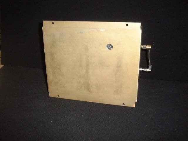
MKRU519
Mar 05, 20019 Antenna InstaScan Scanner, Model U519
Equipment Class
DSS - Part 15 Spread Spectrum Transmitter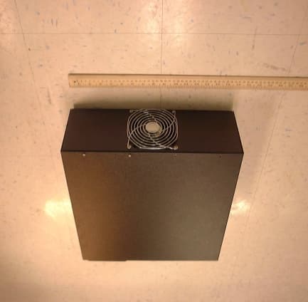
MKRS556
May 22, 2000Model S556 Scanner
Equipment Class
TNB - Licensed Non-Broadcast Station Transmitter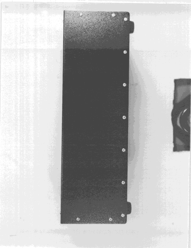
MKRS416
Jul 26, 1999DSS - Part 15 Spread Spectrum Transmitter
Equipment Class
DSS - Part 15 Spread Spectrum Transmitter