MKRS556-EPRFID Transciever
Single Chip Systems Corporation
Click to zoom
Application Details
- Equipment Class
- TNB - Licensed Non-Broadcast Station Transmitter
- Date of Grant
- Mar 11, 2001
- Application Purpose
- Original Equipment
- Date of Application
- Dec 28, 2000
- Equipment Note
- RFID Transciever
- Frequency Range
- 2453.00000000 - 2481.00000000
- Country
- United States
Documents & Files
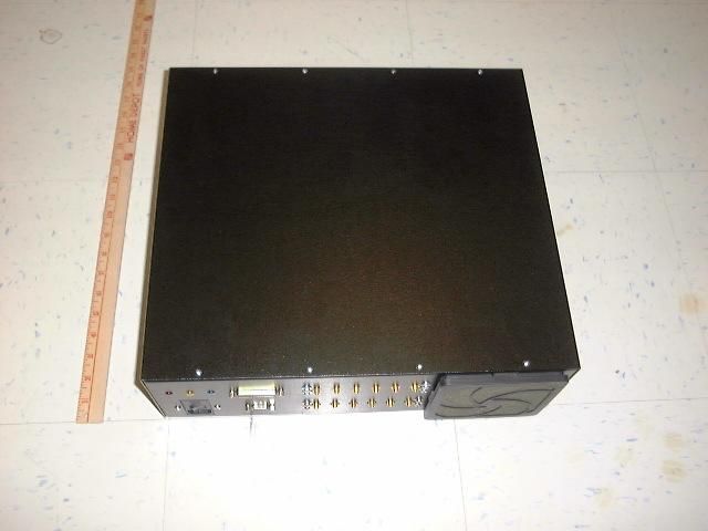
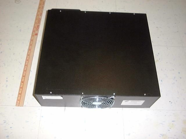
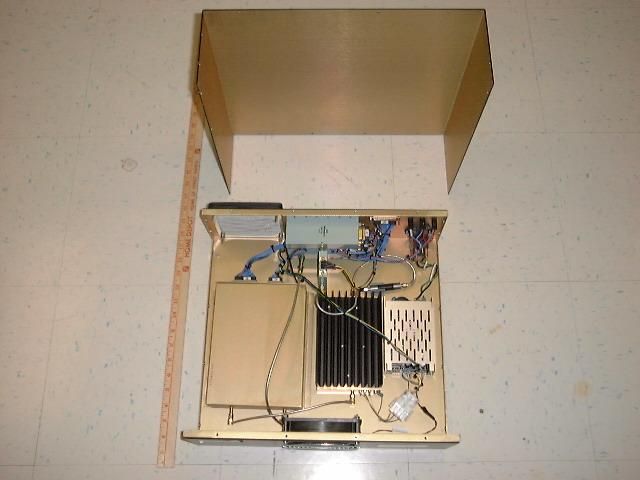
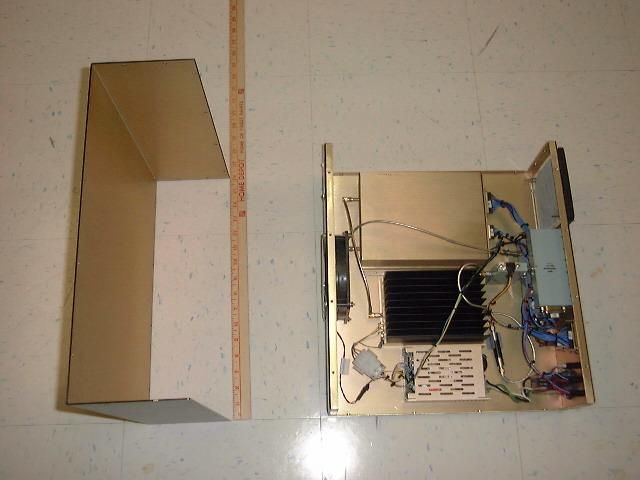
Document Text
Text extracted from the exhibit documents filed with the FCC. Open a document above to read the original.
Users Manual
INSTASCAN © SCANNER MODEL S556-EP Operations Manual SCS Corporation 10905 Technology Place, San Diego, CA 92127 Phone: 858-485-9196 • Fax: 858-485-0561 www.scs-corp.com • [email protected] The products and programs described in this Operations Manual are licensed products of SCS. This Operations Manual contains proprietary information protected by copyright and this Operations Manual and all accompanying hardware, software, and documentation are copyrighted. SCS does not warrant that the hardware will work properly in all environments and applications, and makes no warranty and representation, either implied or expressed, with respect to the quality, performance, or fitness for a particular purpose. Information in this Operations Manual is subject to change without notice and does not represent a commitment on the part of SCS. SCS assumes no responsibility for incidental damage that may result do to any inaccuracies that may be contained in this Operations Manual. SCS makes no commitment to update or keep current the information in this Operations Manual, and reserves the right to make changes to this Operations Manual and/or product without notice. No part of this manual may be reproduced or transmitted in any form or by any means, electronic or mechanical, including photocopying, recording, or information storage and retrieval systems, for any purpose other than the purchaser’s personal use, without the express written permission of SCS. IBM is a registered trademark of International Business Machines Corporation. MS-DOS and Windows are registered trademarks of Microsoft Corporation. All other trademarks or registered trademarks listed belong to their respective owners. InstaScan and Dura-label are trademarks of SCS Corporation. Version 100479-2 Rev.A September ©Copyright 2000 SCS 10905 Technology Place San Diego, CA 92127 ii iii Contents Chapter 1— Introduction.......................................................1 Advantages....................................................................2 S556-EP InstaScan Scanner.............................................4 What Else You Need........................................................5 Summary of Chapters......................................................6 Chapter 2 — Installation.......................................................7 LEDs and Connectors......................................................7 Scanner Front / Scanner Rear...........................................8 Scanner Installation Steps..............................................10 Connecting External Antennas........................................11 Placing the Antennas.....................................................12 Connecting to a PC Serial Port or RS-232.......................13 Connecting to an AC Outlet...........................................14 Configuring the Scanner................................................15 Aligning the Antenna.....................................................18 Installing Dura-labels....................................................19 Reading Information from your Dura-labels.....................20 Writing Information to your Dura-label............................21 Loading Your Application...............................................22 Chapter 3 — RF Communications........................................23 Signal Interference........................................................24 Signal Attenuation/Reflections........................................25 Optimizing Performance................................................26 iv Chapter 4 — Troubleshooting..............................................27 Solving Problems...........................................................27 Contacting Customer Service.........................................30 Returning Your System....................................................31 Chapter 5 — Specifications.................................................32 SCS Patents..................................................................32 S556-EP Specifications..................................................33 Chapter 6 — DB-25 Connector Function...............................35 Receive Antenna Select Lines..........................................36 Transmit Antenna Select Lines.........................................37 Peripheral Inputs...........................................................37 Peripheral Outputs........................................................38 Limited Warranty...........................................................40 FCC Part 90 Compliance..............................................40 Radio Frequency exposure limits.....................................41 Disclaimer....................................................................41 1 Chapter 1 Introduction T he S556-EP InstaScan scanners and Dura-label Radio Frequency (RF) Identification Tags developed by SCS are state-of-the-art data gathering and inspection systems that combine sophisticated Interactive Identification technology in a compact form factor. This unique synergy allows our system to integrate seamlessly into — and significantly increase productivity for — a wide range of applications and environments. This system consists of the following components: A scanner that is capable of writing information to and reading information from Dura-labels using a read/write head (antenna). The scanner conforms to FCC Part 90 specifications and can operate with one to six externally connected antennas. Dura-label RF tags that contain information programmed by the scanner. These tags are designed to store information under extremely harsh environments without requiring a battery, and the read/write Dura-labels can store a permanent record of multiple events and transactions. Communications between the scanner and tags are conducted using a revolutionary two-way technology that provides superior advantages over conventional communication methods. The specific data being commu…
Text truncated - open the document above for the full version.
Users Manual
INSTASCAN © SCANNER MODEL S556-EP Operations Manual SCS Corporation 10905 Technology Place, San Diego, CA 92127 Phone: 858-485-9196 • Fax: 858-485-0561 www.scs-corp.com • [email protected] 556-EP Manual cover.p651/18/2001, 2:47 PM1 The products and programs described in this Operations Manual are licensed products of SCS. This Operations Manual contains proprietary information protected by copyright and this Operations Manual and all accompanying hardware, software, and documentation are copyrighted. SCS does not warrant that the hardware will work properly in all environments and applications, and makes no warranty and representation, either implied or expressed, with respect to the quality, performance, or fitness for a particular purpose. Information in this Operations Manual is subject to change without notice and does not represent a commitment on the part of SCS. SCS assumes no responsibility for incidental damage that may result do to any inaccuracies that may be contained in this Operations Manual. SCS makes no commitment to update or keep current the information in this Operations Manual, and reserves the right to make changes to this Operations Manual and/or product without notice. No part of this manual may be reproduced or transmitted in any form or by any means, electronic or mechanical, including photocopying, recording, or information storage and retrieval systems, for any purpose other than the purchaser’s personal use, without the express written permission of SCS. IBM is a registered trademark of International Business Machines Corporation. MS-DOS and Windows are registered trademarks of Microsoft Corporation. All other trademarks or registered trademarks listed belong to their respective owners. InstaScan and Dura-label are trademarks of SCS Corporation. Version 100479-2 Rev.A September ©Copyright 2000 SCS 10905 Technology Place San Diego, CA 92127 ii 556-EP Manual cover.p651/18/2001, 2:47 PM2 iii Contents Chapter 1— Introduction.......................................................1 Advantages....................................................................2 S556-EP InstaScan Scanner.............................................4 What Else You Need........................................................5 Summary of Chapters......................................................6 Chapter 2 — Installation.......................................................7 LEDs and Connectors......................................................7 Scanner Front / Scanner Rear...........................................8 Scanner Installation Steps..............................................10 Connecting External Antennas........................................11 Placing the Antennas.....................................................12 Connecting to a PC Serial Port or RS-232.......................13 Connecting to an AC Outlet...........................................14 Configuring the Scanner................................................15 Aligning the Antenna.....................................................18 Installing Dura-labels....................................................19 Reading Information from your Dura-labels.....................20 Writing Information to your Dura-label............................21 Loading Your Application...............................................22 Chapter 3 — RF Communications........................................23 Signal Interference........................................................24 Signal Attenuation/Reflections........................................25 Optimizing Performance................................................26 556-EP Manual cover.p651/18/2001, 2:47 PM3 iv Chapter 4 — Troubleshooting..............................................27 Solving Problems...........................................................27 Contacting Customer Service.........................................30 Returning Your System....................................................31 Chapter 5 — Specifications.................................................32 SCS Patents..................................................................32 S556-EP Specifications..................................................33 Chapter 6 — DB-25 Connector Function...............................35 Receive Antenna Select Lines..........................................36 Transmit Antenna Select Lines.........................................37 Peripheral Inputs...........................................................37 Peripheral Outputs........................................................38 Limited Warranty...........................................................40 FCC Part 90 Compliance..............................................40 Radio Frequency exposure limits.....................................41 Disclaimer....................................................................41 556-EP Manual cover.p651/18/2001, 2:47 PM4 1 Chapter 1 Introduction T he S556-EP InstaScan scanners and Dura-label Radio Frequency (RF) Identification Tags developed by SCS are state-of-the-art data gathering and inspection systems that combine sophisticated Interactive Identification technology in a compact form factor. This unique synergy allows our system to integrate seamlessly into — and significantly increase productivity for — a wide range of applications and environments. This system consists of the following components: A scanner that is capable of writing information to and reading information from Dura-labels using a read/write head (antenna). The scanner conforms to FCC Part 90 specifications and can operate with one to six externally connected antennas. Dura-label RF tags that contain information programmed by the scanner. These tags are designed to store information under extremely harsh environments without requiring a battery, and the read/write Dura-labels can store a permanent record of multiple events and transactions. Communications between the scan…
Text truncated - open the document above for the full version.
Users Manual
INSTASCAN © SCANNER MODEL S556-EP Operations Manual SCS Corporation 10905 Technology Place, San Diego, CA 92127 Phone: 858-485-9196 • Fax: 858-485-0561 www.scs-corp.com • [email protected] 556-EP Manual cover.p652/27/2001, 3:16 PM1 The products and programs described in this Operations Manual are licensed products of SCS. This Operations Manual contains proprietary information protected by copyright and this Operations Manual and all accompanying hardware, software, and documentation are copyrighted. SCS does not warrant that the hardware will work properly in all environments and applications, and makes no warranty and representation, either implied or expressed, with respect to the quality, performance, or fitness for a particular purpose. Information in this Operations Manual is subject to change without notice and does not represent a commitment on the part of SCS. SCS assumes no responsibility for incidental damage that may result do to any inaccuracies that may be contained in this Operations Manual. SCS makes no commitment to update or keep current the information in this Operations Manual, and reserves the right to make changes to this Operations Manual and/or product without notice. No part of this manual may be reproduced or transmitted in any form or by any means, electronic or mechanical, including photocopying, recording, or information storage and retrieval systems, for any purpose other than the purchaser’s personal use, without the express written permission of SCS. IBM is a registered trademark of International Business Machines Corporation. MS-DOS and Windows are registered trademarks of Microsoft Corporation. All other trademarks or registered trademarks listed belong to their respective owners. InstaScan and Dura-label are trademarks of SCS Corporation. Version 100713-1 ©Copyright 2000 SCS 10905 Technology Place San Diego, CA 92127 ii 556-EP Manual cover.p652/27/2001, 3:16 PM2 iii Contents Chapter 1— Introduction.......................................................1 Advantages....................................................................2 S556-EP InstaScan Scanner.............................................4 What Else You Need........................................................5 Summary of Chapters......................................................6 Chapter 2 — Installation.......................................................7 LEDs and Connectors......................................................7 Scanner Front / Scanner Rear...........................................8 Scanner Installation Steps..............................................10 Connecting External Antennas........................................11 Placing the Antennas.....................................................12 Connecting to a PC Serial Port or RS-232.......................13 Connecting to an AC Outlet...........................................14 Configuring the Scanner................................................15 Aligning the Antenna.....................................................18 Installing Dura-labels....................................................19 Reading Information from your Dura-labels.....................20 Writing Information to your Dura-label............................21 Loading Your Application...............................................22 Chapter 3 — RF Communications........................................23 Signal Interference........................................................24 Signal Attenuation/Reflections........................................25 Optimizing Performance................................................26 556-EP Manual cover.p652/27/2001, 3:16 PM3 iv Chapter 4 — Troubleshooting..............................................27 Solving Problems...........................................................27 Contacting Customer Service.........................................30 Returning Your System....................................................31 Chapter 5 — Specifications.................................................32 SCS Patents..................................................................32 S556-EP Specifications..................................................33 Chapter 6 — DB-25 Connector Function...............................35 Receive Antenna Select Lines..........................................36 Transmit Antenna Select Lines.........................................37 Peripheral Inputs...........................................................37 Peripheral Outputs........................................................38 Limited Warranty...........................................................40 FCC Part 90 Compliance..............................................40 Radio Frequency exposure limits.....................................41 Disclaimer....................................................................41 556-EP Manual cover.p652/27/2001, 3:16 PM4 1 Chapter 1 Introduction T he S556-EP InstaScan scanners and Dura-label Radio Frequency (RF) Identification Tags developed by SCS are state-of-the-art data gathering and inspection systems that combine sophisticated Interactive Identification technology in a compact form factor. This unique synergy allows our system to integrate seamlessly into — and significantly increase productivity for — a wide range of applications and environments. This system consists of the following components: A scanner that is capable of writing information to and reading information from Dura-labels using a read/write head (antenna). The scanner conforms to FCC Part 90 specifications and can operate with one to six externally connected antennas. Dura-label RF tags that contain information programmed by the scanner. These tags are designed to store information under extremely harsh environments without requiring a battery, and the read/write Dura-labels can store a permanent record of multiple events and transactions. Communications between the scanner and tags are…
Text truncated - open the document above for the full version.
ID Label/Location Info
MKRS556-EP NamePlate Information The information below is excerpted from the TEST REPORT FOR TYPE ACCEPTANCE of TRANSCEIVER MODEL S556-EP FCC ID MKRS556-EP that was submitted to the FCC on December 29, 2000. The Submission Confirmation Number is EA99662. The nameplate is affixed permanently to the upper left corner of the rear panel of the MKRS556-EP. The nameplate size is 2.5” x 2.0”
Operational Description
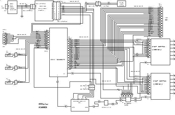
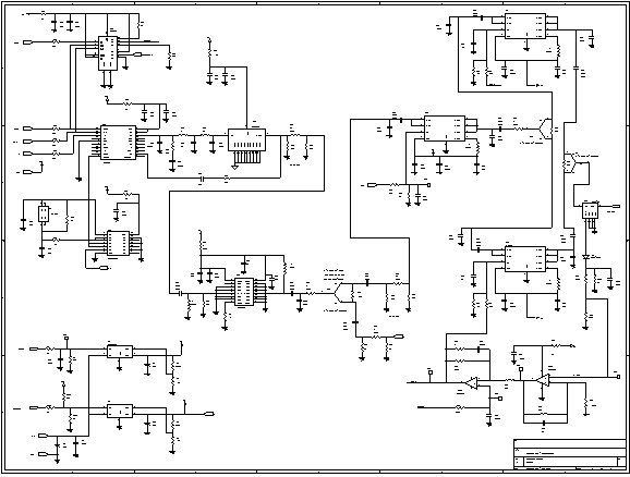
The information below is excerpted from the TEST REPORT FOR TYPE ACCEPTANCE of TRANSCEIVER MODEL S556-EP FCC ID MKRS556-EP that was submitted to the FCC on December 29, 2000. The Submission Confirmation Number is EA99662. 1. Circuit Diagrams and Descriptions The top-level circuit diagram for the entire system is shown below in Figure 1. The Transmitter section is shown in Figure 2. Figure 1. MKRS556-EP Top Level Schematic Diagram Figure 2. MKRS556-EP Transmitter Section Schematic Diagram A. Description of frequency determining circuitry The RF frequency is generated using a phase locked loop (PLL) circuit. The licensed frequency data is burned into flash memory. At startup the microprocessor sends the PLL integrated circuit (National Semiconductor’s LMX2325TM) the serial information for the set frequency. The PLL IC uses a 20 MHz crystal oscillator as a reference frequency. The PLL IC generates a voltage for the voltage-controlled oscillator (VCO). The VCO generates the RF signal, which is fed back to the PLL IC. The PLL IC divides this signal down, and compares it to the 20 MHz reference. In the closed control loop, the PLL IC’s output voltage is adjusted to precisely maintain the set frequency. B. Description of circuitry used for spurious, modulation and power limiting The MKRS556-EP RF output is on/off modulated. This modulation is accomplished using the analog gain control pin of an RF amplifier (RF Micro Devices RF2126). This gain control is set with a discrete signal from the field programmable gate array (FPGA). An RC filter on this line provides transmission bandwidth limiting. A 3 section, low-pass filter located at the output of the final RF amplifier limits harmonic emissions. The RF output power level is set using an analog control voltage in the amplification stage prior to the final amplifier. During final assembly, a digital potentiometer is adjusted to provide a desired output power at the RF output port. The digital potentiometer value that corresponds to the desired output power is then burned into flash memory. C. Description of Modulation technique and circuitry The MKRS556-EP Transceiver uses an RF on/off modulation scheme. The RF signal powers the ID tag in the field, and then communicates with the tag by briefly turning off the RF power at the proper time. The waveform timing and duty cycle depend on the transmitted symbol. There are 3 transmitter waveforms. In the alternative, the transceiver sends a clock, a logic “0”, or a logic “1”. Figure 1 shows the timing for each of these waveforms. The modulation either has the RF at full strength in the “on” state or attenuated by at least 20 dB in the off state. Any time the scanner is normally operating, the RF signal is continuously being modulated. The system is operating CW (un-modulated) only when the transceiver is instructed to operate as such, via operator command. The sequence of clock, logic “0” and logic “1” information being transmitted depends on the commands issued by the processor and by the tag responses. The modulation of the signal is controlled with a digital pulse sequence from the FPGA. This signal is RC filtered to limit the transmission bandwidth, and then is sent to the analog gain control of an RF amplifier. The RF amplifier attenuates the RF signal by a minimum of 20 dB when in the “off” state. RF RF OFF (Down 26 dB) 40-55 2 us 2 us 1.4 RF RF OFF (Down 26 dB) 40-55 2 us 2 us 1.4 2 1.4 LOGIC “0” TRANSMITTED LOGIC “1” TRANSMITTED RF RF OFF (Down 26 dB) 30 us 2 us CLOCK ONLY RF RF OFF (Down 26 dB) 30 us 2 us 2 us 1.0 RF RF OFF (Down 26 dB) 30 us 2 us 2 us 1.0 2 1.0 LOGIC “0” TRANSMITTED LOGIC “1” TRANSMITTED Figure 3. Modulation Modes of the MKRS556 Transceiver
RF Exposure Info
February 13, 2001 FCC Application Processing Branch Regarding: FCC ID MKRS556-EP Form 731 Confirmation Number EA99662 Correspondence Reference Number 18069 1. The Necessary Bandwidth as defined in CFR 47 part 2.202 (c) (4) is 714 kHz. This value was submitted in the Test Data Report (section 4). The modulation was expressed incompletely as K1D, the more accurate expression, in accordance with CFR 47 parts 2.201 and 2.202 (b) would be 714KK1D. 2. The MPE in the uncontrolled case is 1 mw/cm 2 (OET Bulletin 65 Appendix A). The gain of the antenna that is sold with this system is 8 dBi. Rewriting equation (3) from OET Bulletin 65 Section 2, R = ½ * sqrt ((P*G)/(pi*S)). P = 5000 mW G = 6.3 numeric (8dBi) S = 1 mW/ cm 2 Solving, the range at which the field intensity falls below the MPE is 50.1 cm, or 19.7 inches. We added a 10% “fudge factor” in our expression of 22 inches as the uncontrolled range in our User’s Manual. Regards, Gary Bann
RF Exposure Info
February 19, 2001 FCC Application Processing Branch Regarding: FCC ID MKRS556-EP Form 731 Confirmation Number EA99662 Correspondence Reference Number 18069 On February 13, I sent you a quick, “off-the-top-of-my-head” calculation showing how we arrived at the MPE figure for the MKRS556-EP device. Upon reviewing my data, I find that I only provided the calculation for the uncontrolled case, and slightly overstated the gain of our antenna. Here are the corrected calculations. 1. The MPE in the uncontrolled case is 1 mw/cm 2 (OET Bulletin 65 Appendix A). The gain of the antenna that is sold with this system is 7.8 dBi. Rewriting equation (3) from OET Bulletin 65 Section 2, R = ½ * sqrt ((P*G)/(pi*S)). P = 5000 mW G = 6.0 numeric (7.8dBi) S = 1 mW/ cm 2 Solving, the range at which the field intensity falls below the MPE is 48.8 cm, or 19.2 inches. 2. The MPE in the controlled case is 5 mw/cm 2 (OET Bulletin 65 Appendix A). The equivalent calculation in this case with S = 5 mw/cm 2 finds R = 21.9 cm, or 8.6 inches. 3. I note that the manual states a range in inches of 8.5” instead of 8.6”. This is being corrected. Regards, Gary Bann SCS Corporation 858-485-9196 x 109 [email protected]
RF Exposure Info
February 27, 2001 FCC Application Processing Branch Regarding: FCC ID MKRS556-EP Form 731 Confirmation Number EA99662 Correspondence Reference Number 18221 Responding in turn to each of your questions: 1) This device operates with 6 antennas. It is noted that no more than one antenna transmits at any given time. Each antenna has two cables. The operational description did not elaborate on this. Please elaborate on the function of the two cables going to each antenna. Each antenna referred to is actually two identical helical antennas contained in one housing. In normal operation one of the pair is used as a transmit antenna, the other as a receive antenna. Because the system is transmitting and receiving at the same time, sufficient isolation between the transmitter and receiver is achieved by using separate antennas. The MKRS556-EP provides the capability to swap the pair around, so that the original transmit antenna in the pair is now the receive antenna and vice versa. To answer your question directly, each cable is an RF cable, capable of either being used for transmission or reception. 2) In this application, MPE was for the Occupational/Controlled Environment limit. A previous application (EA99257) for a similar device used the General Population/Uncontrolled Environment limit. It is suggested that you submit new exhibits for this application using the General Population/Uncontrolled Environment limit and using the similar application as a model. This application does not have any information indicating that the Occupational/Controlled Environment limit would be applicable for MPE. I am resubmitting the MPE calculations you requested for the General Population /Uncontrolled case only. Further, changes to the Operation Manual similar to those of the EA99257 application are being resubmitted. The MPE in the uncontrolled/general population case is 1 mw/cm 2 (OET Bulletin 65 Appendix A). The gain of the antenna that is sold with this system is 7.8 dBi. Rewriting equation (3) from OET Bulletin 65 Section 2, R = ½ * sqrt ((P*G)/(pi*S)). P = 5000 mW G = 6.0 numeric (7.8dBi) S = 1 mW/ cm 2 Solving, the range at which the field intensity falls below the MPE is 48.9 cm, or 19.2 inches. We rounded to 20 inches in our manual. Regards, Gary Bann SCS Corporation 858-485-9196 x109 [email protected]
RF Exposure Info
12 Placing the Antenna Antenna placement is critical to ensuring that information is transmitted to and from tags accurately. Observe the following guidelines when plac- ing the antenna: Locate the antenna away from metal objects, microwave ovens, and other devices that may induce radio frequency interference. In addition, make sure there are no metallic surfaces between, or in relative proximity to, the scanner and tag. For additional placement considerations, refer to “RF Communications” on page 23. When reading, the antenna should be placed no more than 60 inches from the objects bearing tags. When writing, the antenna should be no more than 20 inches from objects bearing tags Caution: to meet FCC RF Exposure compliance, operator(s) should not be closer than 20 inches to a transmitting antenna. See RF Exposure precautions on page 41. The front of the antenna must be free of obstructions. Otherwise, information may not be written to and read from tags accurately. IAntennas must be labelled indicating minimum separation distance per FCC RF Exposure requirements (page 41). If the information on the label is not clearly visible, a sign with the same information must be posted within 36” of the antenna. (see last page of this manual) ITags must reside within the scan field for at least 3 milliseconds for information to be retrieved from them. 556-EP Manual.P653/7/2001, 2:02 PM12 RF Exposure "Caution" Label Purpose: To meet FCC requirements with regard to RF Exposure, for applications where an individual antenna is used in conjunction with an SCS S556-EP InstaScan® scanner, the antenna must have affixed to it, a label indicating the minimum separation distance required to meet FCC RF Exposure compliance. See sample label below. Specifications Size: 1" x 3" Stock: White, adhesive-backed Sample Label: Placement: Label will be placed on antenna radome surface such that it is clearly visible/legible at a distance of no less than 9 inches from the transmitting antenna, to the operator or any persons who may enter the vicinity of the antenna. Exception: If this is not feasible to affix a label to the antenna radome such that it is visible/legible due to the restraints of a particular application, a "Caution" sign must be posted within 36 inches of the antenna, such that the verbiage on the sign is clearly visible/legible at a distance no closer than 20 inches from the transmitting antenna, to any person who may enter the vicinity of the antenna. See RF Exposure "Caution" Sign Specifications. RF Exposure "Caution" Sign Purpose: To meet FCC requirements with regard to RF Exposure, for applications where a group of RF antennas is used in conjunction with an SCS S556-EP InstaScan® scanner, a sign must be posted indicating the minimum separation distance required to meet FCC RF Exposure compliance. See sample sign below. Specifications Size: 5.5" x 8.5" Stock: White, 90lb card stock, printed and inserted into Users Manual as back cover with perforation, to be torn out and posted as necessary Sample Sign: Placement: In applications that require a group of antennas, a "Caution" sign must be posted within 36 inches of the antennas, such that the verbiage on the sign is clearly legible at a distance no closer than 20 inches from the transmitting antenna, to any person who may enter the vicinity of the antenna.
Test Report
SCS Corporation 10905 Technology Place San Diego, CA 92127 Phone:…
Text truncated - open the document above for the full version.
Contact Information
Applicant
Bruce B Roesner(Chief Technical Officer)
Technical Contact
SCS CorporationGary P Bann
[email protected]858-485-9196
10905 Technology Place · San Diego, California · United States
Non-Technical Contact
SCS CorporationJim Kruest
[email protected]858-485-9196
Technical Specifications
| # | Rule Parts | Frequency Range | Power Output | Emission | Tolerance |
|---|---|---|---|---|---|
| 1 | 90 | 2.45 GHz - 2.48 GHz | 4.37 W | 714KK1D | 6.9000000000 ppm |
Other Applications from Single Chip Systems Corporation

MKRS512-C
Aug 08, 2002InstaScan Scanner, Model 512-C
Equipment Class
DSS - Part 15 Spread Spectrum Transmitter
MKRU519
Mar 05, 20019 Antenna InstaScan Scanner, Model U519
Equipment Class
DSS - Part 15 Spread Spectrum Transmitter
MKRS556
May 22, 2000Model S556 Scanner
Equipment Class
TNB - Licensed Non-Broadcast Station Transmitter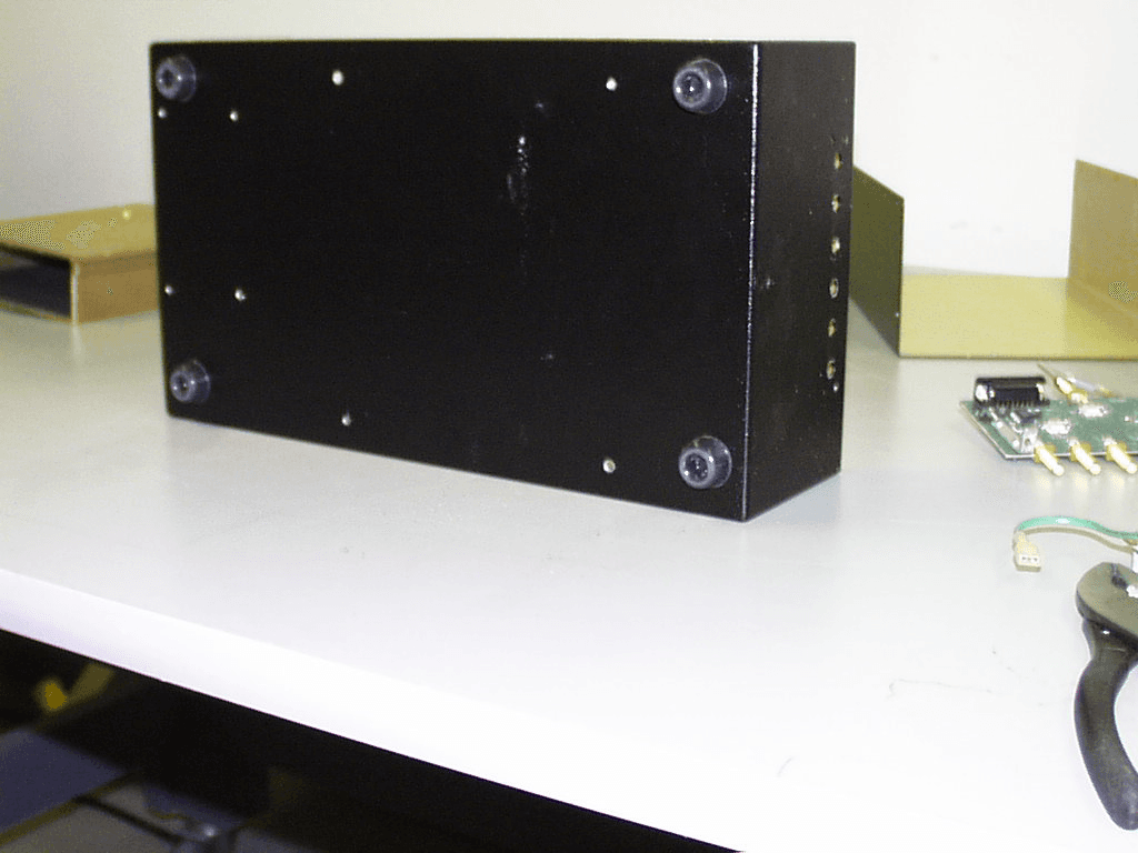
MKRS516
May 07, 20006 Antenna InstaScan Scanner
Equipment Class
DSS - Part 15 Spread Spectrum Transmitter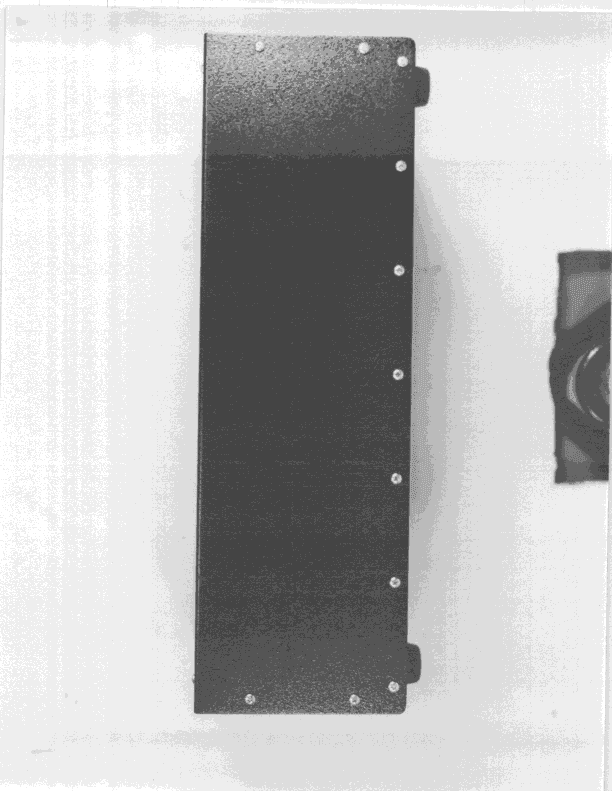
MKRS416
Jul 26, 1999DSS - Part 15 Spread Spectrum Transmitter
Equipment Class
DSS - Part 15 Spread Spectrum Transmitter