MKRS556Model S556 Scanner
Single Chip Systems Corporation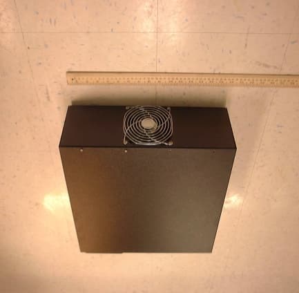
Click to zoom
Application Details
- Equipment Class
- TNB - Licensed Non-Broadcast Station Transmitter
- Date of Grant
- May 22, 2000
- Application Purpose
- Original Equipment
- Date of Application
- Apr 12, 2000
- Equipment Note
- Model S556 Scanner
- Frequency Range
- 2453.00000000 - 2481.00000000
- Country
- United States
Documents & Files
Document Text
Text extracted from the exhibit documents filed with the FCC. Open a document above to read the original.
Users Manual
SCS I NSTA S CAN S CANNER M ODEL S556 O PERATIONS M ANUAL Single Chip Systems 10905 Technology Place San Diego, CA 92127 Phone: 858-485-9196 Fax: 858-485-0561 www.scs-corp.com [email protected] ii The products and programs described in this Operations Manual are licensed products of SCS. This Operations Manual contains proprietary information protected by copyright and this Operations Manual and all accompanying hardware, software, and documentation are copyrighted. SCS does not warrant that the hardware will work properly in all environments and applications, and makes no warranty and representation, either implied or expressed, with respect to the quality, performance, or fitness for a particular purpose. Information in this Operations Manual is subject to change without notice and does not represent a commitment on the part of SCS. SCS assumes no responsibility for incidental damage that may result do to any inaccuracies that may be contained in this Operations Manual. SCS makes no commitment to update or keep current the information in this Operations Manual, and reserves the right to make changes to this Operations Manual and/or product without notice. No part of this manual may be reproduced or transmitted in any form or by any means, electronic or mechanical, including photocopying, recording, or information storage and retrieval systems, for any purpose other than the purchaser's personal use, without the express written permission of SCS. This document represents a version 100144-2 of the Operations Manual. As a result, some items described herein may not currently be available. IBM is a registered trademark of International Business Machines Corporation. MS-DOS and Windows are registered trademarks of Microsoft Corporation. All other trademarks or registered trademarks listed belong to their respective owners. InstaScan and Dura-label are trademarks of SCS Corporation. Version 100144-2 September, 1999 Copyright 1999 SCS 10905 Technology Place San Diego, California 92127 iii Contents Chapter 1-- Introduction....................................................................... 1 Advantages................................................................................2 S556 InstaScan Scanner............................................................4 Conventions in This Manual.....................................................5 What Else You Need..................................................................5 Summary of Chapters................................................................6 Chapter 2 -- Installation........................................................................ 7 Panel Information......................................................................8 InstaScan Scanner Installation Steps........................................9 Connecting External Antennas...............................................10 Placing the Antennas..............................................................11 Connecting to a PC Serial Port...............................................12 Connecting to an AC Outlet...................................................13 Configuring the Scanner.........................................................14 Aligning the Scanner...............................................................16 Installing Dura-labels..............................................................17 Reading Information from your Dura-labels...........................17 Loading Your Application.......................................................18 Chapter 3 -- RF Communications......................................................19 Signal Interference...................................................................20 Signal Attenuation/Reflections...............................................21 Optimizing Performance.........................................................22 iv Chapter 4 -- Troubleshooting.............................................................23 Solving Problems.....................................................................23 Contacting Customer Service..................................................25 Returning Your System...........................................................27 Chapter 5 -- Specifications .................................................................29 SCS Patents.............................................................................29 InstaScan Scanner Specifications............................................30 Page 1 Chapter 1 Introduction he scanners and Dura-labels developed by SCS are state-of- the-art data gathering and inspection systems that combine sophisticated Interactive Identification technology in a compact form factor. This unique synergy allows our system to integrate seamlessly into and significantly increase productivity for a wide range of applications and environments. These systems consist of Dura-labels that are designed to store information under extremely harsh environments without requiring a battery and scanners capable of reading the Dura-labels. Communications between the scanner and Dura-label are conducted using a revolutionary two-way technology that provides superior advantages over conventional communication methods. The specific data being communicated, and the amount of interaction you have with the scanner and Dura-label, may be determined by your application. T Page 2 Advantages Data-gathering systems such as bar code readers and conventional Radio Frequency Identification products use one-way communication: a sensor reads information from a device, without any interaction between the two devices. Moreover, bar code systems are subject to line-of-sight limitations. As a result, airborne contaminants such as dust, dirt, oil, and mist, as well as label damage and objects residing outside the line of sight, result in inefficient and erroneous results. The SCS Interactive Identification System overcomes these restrictions by using state-of-th…
Text truncated - open the document above for the full version.
External Photos
Section 2.1033(c)(12) – External Photographs Photographs showing the equipment construction and layout are shown below. Front View of MKRS556 Scanner Rear View of MKRS556 Scanner
ID Label/Location Info
Section 2.1033(c)(11) - Equipment Identification Plate The figure below shows the identification plate. The following figure shows the location of the equipment identification place on the MKRS556 scanner.
Internal Photos
Section 2.1033(c)(12) – Internal Photographs Top View of MKRS556 Scanner Side View of MKRS556 Scanner
Operational Description
Single Chip Systems Corporation MODEL MKRS556 SCANNER Operational Description Purpose: This device is intended for applications in the areas of identification, verification, and inventory control. The system consists of two main parts, a reader and ID tags. The reader is operated by the user to interrogate the tags which are attached to objects in the field. Tags are small in size and have read/write capability. Theory of Operation: The ID tags derive their power from the RF energy of the reader signal, and are not internally powered. Signaling from reader to tag is accomplished by momentarily switching off the RF transmitter in a predetermined pattern. Signaling from tag to reader is accomplished though antenna backscatter. The tag momentarily shorts its antenna terminals together, which causes the transmitted power that was being absorbed into the tag to reflect back off its antenna. This reflected signal sensed by the receiver. Transmitter: The transmitter produces a phase locked CW signal, which is modulated by momentarily switching off the output power. In the transmitter, the phase locked loop output is amplified and then modulated by an RF sw itch w hich is also controlled by the microprocessor. It then passes through the final amplifier, low pass filter, SP6T switch, and ultimately is transmitted from the antenna. Re ce ive r: The received signal from the antenna, comes through the SP6T sw itch, to a pow er divider. The tw o signals from the power divider are quadrature downconverted (to baseband) using an LO derived from the transmitter. The two baseband signals are amplified and filtered, the absolute values are taken, and the two resultant signals are summed. This composite baseband signal goes to a comparitor circuit which provides an input signal to the microprocessor. Ante nna: The model MKRS556 scanner can use up to 6 transmit and receive antennas. Power: Antenna port power is less than 37 dBm. The typical antenna gain will be 7.5 dBi. Modulated Signal Bandwidth: The 20 dB bandwidth of the modulated signal power is less than 1 MHz.
Parts List/Tune Up Info
Name: Model S556 ScannerNumber: 100368 SCS CORPORATION Revision: - Revision Date: ITEM QTY REF. DES . DESCRIPTION MANUFACTURE R PART NO. UNIT EXTENDED DISTRIBUTOR S DIST. PART NO. NO. COST COST 0 NEXT S556 System SCS 100367 1 1 Model S511 Scanner SCS 100390 337.75 $337.75 2 1 Fabrication Drawing, Model S556 Housing, Top Side SCS 100108-21 43.26 $43.26 3 1 Fabrication Drawing, Model S556 Housing, Bottom Side SCS 100317 75.00 $75.00 4 1 Fabrication Drawing, Main Wiring Harness SCS 100374 31.91 $31.91 5 1 Fabrication Drawing, Wiring Harness SCS 100375 3.49 $3.49 6 1 Circuit Board Assembly, SP6T Switch SCS 100398 113.02 $113.02 7 1 Switch, SP6T, High Power Microsemi 75430-68 675.00 $675.00 L&M 8 1 Power Supply, Triple Output Digital Power USC-100-350 94.00 $94.00 Foresight 9 1 High Power Amplifier SCS 100377 405.86 $405.86 10 1 Fabrication Drawing, Mounting Bracket, SP6T Switch SCS 100366 8.50 $8.50 11 1 Label, FCC SCS 100376 1.00 $1.00 12 1 Low Pass Filter K&L Microwave 3 L120-2750/T4900-0/0 65.00 $65.00 13 1 Cable Assembly, SMA, 4" QMI 1-3636-601-5204 14.50 $14.50 Richardson 14 1 Cable Assembly, SMA, 8" QMI 1-3636-601-5208 14.72 $14.72 Richardson 15 1 Cable Assembly, Right Angle SMA, 9" QMI 1-3737-601-3209 28.26 $28.26 Richardson 16 1 Cable Assembly, Right Angle and Straight SMA, 12" QMI 1-3637-601-5212 22.23 $22.23 Richardson 17 1 DC Fan Comair Rotron MC12B3 16.93 $16.93 Digi-Key CR051-ND 18 1 120mm Fan Filter Assy Allied 609-5613 2.89 $2.89 19 1 120mm Fan Guard Allied 599-0415 2.48 $2.48 20 1 120mm Fan Filter (Metal Screen) Allied 609-5629 5.91 $5.91 21 1 Fuse, 2A, fast-acting, 0.25"x1.25" Digi-Key 283-2020-ND 0.24 $0.24 22 1 LED, Red, Leaded Lumex SSL-LX5093LID 0.12 $0.12 Digi-Key 67-1110-ND 23 1 LED, Green, Leaded Lumex SSL-LX5093LGD 0.12 $0.12 Digi-Key 67-1108-ND 24 1 LED, Yellow, Leaded Lumex SSL-LX5093LYD 0.12 $0.12 Digi-Key 67-1111-ND 25 1 Connector, 2 pin, male Molex 70107-0001 0.54 $0.54 Digi-Key WM-2533-ND 26 2 Terminals, Crimp Molex 16-02-0114 0.08 $0.16 Digi-Key WM-2517-ND 27 A/R Cable Clamp Richco CFCC-3-05A-RT 0.23 $2.30 Digi-Key RP391-ND 28 6 Screw, machine thread 6-32 x 1/4", pan head, Phillips, SS 0.02 $0.12 Pellmell 29 18 Lock washer, split ring, #6, SS 0.01 $0.18 Pellmell 30 12 washer, #6, 3/8" span 0.01 $0.12 Pellmell 31 4 Screw, machine thread 6-32 x 5/8", flat head, Phillips, SS 0.02 $0.08 Pellmell 32 4 Screw, machine thread 6-32 x 1.75", pan head, Phillips, SS 0.02 $0.08 Pellmell 33 24 Screw, machine thread 4-40 x 1/4", pan head, Phillips, SS 0.02 $0.48 Pellmell 34 2 Jack screw set, 4-40 x 3/4", female lock AMP 207719-1 0.77 $1.54 Digikey A9007-ND 35 10 Lock washer, split ring, #4, SS 0.01 $0.10 Pellmell 36 12 washer, #4, 5/16" span 0.01 $0.12 Pellmell 37 6 Nut, hex, machine thread 4-40, 1/4" span, SS 0.02 $0.12 Pellmell 38 10 Screw, machine thread 4-40 x 3/8", pan head, Phillips, SS 0.50 $5.00 Pellmell 39 6 Lock washer, 1/4" star, gold plated 0.02 $0.12 Pellmell 40 6 Nut, hex, machine thread 1/4-36, 5/16" span, gold plated 0.02 $0.12 Pellmell 41 4 Standoff, bumpon, black, 0.88"Wx0.4"H Digi-Key SJ5009-0-ND 0.30 $1.20 Digi-Key SJ5009-0-ND 42 1 Mounting Clip, Adhesive Backed McMaster 7565K61 0.30 $0.30 43 4 Screw, machine thread 6-32 x 3/16", pan head, Phillips, SS 0.02 $0.08 Pellmell 44 REF Assembly Procedure, Model S556 Scanner 100370 45 REF Test Procedure, Model S556 Scanner 100369 46 REF Schematic Diagram, Model S556 Scanner 100371 Total Cost $1,975.07 Assy time=1.5 hourstest time=0.5 hours Printed 4/28/00 8:03 PM
Schematics
Section 2.1033(c)(10) - Circuit Diagrams and Descriptions The top level circuit diagram for the entire system is shown below in Figure 1. Figure 1. MKRS556 Top Level Schematic Diagram A. Description of frequency determining circuitry The RF frequency is generated using a phase locked loop (PLL) circuit. The licensed frequency data is burned into flash memory. At startup the microprocessor sends the PLL integrated circuit (National Semiconductor’s LMX2325TM) the serial information for the set frequency. The PLL IC uses a 20 MHz crystal oscillator as a reference frequency. The PLL IC generates a voltage for the voltage controlled oscillator (VCO). The VCO generates the RF signal, which is fed back to the PLL IC. The PLL IC divides this signal down, and compares it to the 20 MHz reference. In the closed control loop, the PLL IC’s output voltage is adjusted to precisely maintain the set frequency. B. Description of circuitry used for spurious, modulation and power limiting The MKR S556 RF output is on/off modulated. This modulation is accomplished using the analog gain control pin of an RF amplifier (RF Micro Devices RF2126). This gain control is set with a discrete signal from the field programmable gate array (FPGA). An RC filter on this line provides transmission bandwidth limiting. Spurious emissions are limited by a 3 section, low-pass filter located at the output of the final RF amplifier. The RF output power level is set using an analog control voltage in the amplification stage prior to the final amplifier. During final assembly, a digital potentiometer is adjusted to provide a desired output power at the RF output port. The digital potentiometer value that corresponds to the desired output power is then burned into flash memory. C. Description of Modulation technique and circuitry The MKR S556 Transceiver uses an RF on/off modulation scheme. The RF signal powers the ID tag in the field, and then communicates with the tag by briefly turning off the RF power at the proper time. The waveform timing and duty cycle depend on the transmitted symbol. There are 3 transmitter waveforms. The transceiver is either sending just a clock, sending a logic “0”, or sending a logic “1”. Figure 2 shows the timing for each of these waveforms. The range of time for the next frame of data or clock varies as a function of the interrupt latency of the microprocessor. The modulation either has the RF at full strength in the “on” state, or attenuated by at least 20 dB in the off state. Any time the scanner is normally operating, the RF signal is continuously being modulated. The system is operating CW (unmodulated) only when the transceiver is instructed to operate as such, via operator command. The sequence of clock, logic “0” and logic “1” information being transmitted is completely dependent on the commands issued by the processor, and by the tag responses. The modulation of the signal is controlled with a digital pulse sequence from the FPGA. This signal is RC filtered to limit the transmission bandwidth, and then is sent to the analog gain control of an RF amplifier. The RF amplifier attenuates the RF signal by a minimum of 20 dB when in the “off” state. RF ON RF OFF (Down 26 dB) 40-55 us 2 us 2 us 1.4 us RF ON RF OFF (Down 26 dB) 40-55 us 2 us 2 us 1.4 us 2 us 1.4 us LOGIC “0” TRANSMITTED LOGIC “1” TRANSMITTED RF ON RF OFF (Down 26 dB) 25-35 us 2 us CLOCK ONLY RF ON RF OFF (Down 26 dB) 40-55 us 2 us 2 us 1.4 us RF ON RF OFF (Down 26 dB) 40-55 us 2 us 2 us 1.4 us 2 us 1.4 us LOGIC “0” TRANSMITTED LOGIC “1” TRANSMITTED Figure 2. Modulation Modes of the MKRS556 Transceiver
Test Report
SCS Corporation 10905 Technology Place San Diego, CA 92127 Phone: 619.485.9196 Fax: 619.485.0561 DATE:April 11, 2000 Federal Communications Commission Equipment Approval Services P.O. Box 358315 Pittsburgh, PA 15251-5315 Attention:Authorization & Evaluation Division Applicant:Single Chip Systems Corporation Equipment:FCC ID: MKR S556 FCC Rules:90.35 Gentlemen: Enclosed please find Test Data Report and all pertinent documentation, the whole for type acceptance of the referenced equipment as shown. Should you need any further information, kindly contact the writer at Single Chip Systems Corporation. Sincerely yours, Eric Mikuteit, Sr. RF Engineer Single Chip Systems Corporation PH: (858) 485-9196 x129 FX: (858) 485-0561 E-mail: [email protected] 1 TEST REPORT FOR TYPE ACCEPTANCE of TRANSCEIVER MODEL S556 FCC ID MKR S556 to FEDERAL COMMUNICATIONS COMMISSION Date of Report:April 11, 2000 2 TABLE OF CONTENTS SECTIONDESCRIPTIONPAGE 1Applicant3 2FCC Identifier3 3Installation and Operating Instructions3 4Type of Emission3 5Frequency Range3 6Range of Operating Power Level3 7Maximum Power Rating3 8DC Voltages and Currents4 9Tuning Procedure4 10Circuit Diagrams and Description4 10.ADescription of frequency determining circuitry4 10.BDescription of circuitry used of spurious, modulation and power limiting 5 10.CDescription of modulation technique and circuitry5 11Equipment Identification Plate5 12Equipment Photographs7 14Testing Data11 14.ARF Output Power11 14.BOccupied Bandwidth12 14.CConducted Spurious Emissions14 14.DField Strength of Spurious Emissions16 14.EFrequency Stability19 3 INTRODUCTION The following information is formatted in accordance with the items required for FCC type acceptance as called out in 47 CFR 2.1033. This application is for a transceiver, or scanner, which is part of an RF ID system, to be used in licensed sites under 47 CFR 90.35. The scanner generates an RF signal between 2.453 and 2.481 GHz. This signal is used to power and communicate with a passive label. The scanner uses externally connected antennas to radiate and receive RF energy. The scanner can selectively multiplex between 1 to 6 antennae. The number of antennae is user configurable depending on the application requirements. The scanner connects to the antennae using 2 flexible coaxial cables. One cable connects to the transmit side of the antenna, and the other connects to the receive side. Single Chip Systems intends to sell 2 types of antennae which have either 7.5 dBi or 8.5 dBi of gain. Again, the number and type of antennae used will depend on the user’s application requirements. 1. Applicant Single Chip Systems Corporation 10905 Technology Place San Diego, CA 92127 Ph: (858) 485-9196 Fx: (858) 485-0561 The applicant is the manufacturer of the equipment. 2. FCC Identifier The unit shall have the FCC identifier MKR S556. 3. Installation and Operating Instructions The operation manual for the MKR S556 is in the process of being written. Enclosed, as an attachment, is a draft copy of the manual. 4. Type of Emission The MKR S556 type of emission is K1D, with a necessary bandwidth of 714 K. 5. Frequency Range The tuned carrier frequency range is 2.453-2.481 GHz. 6. Range of Operating Power The output power of the MKR S556 is adjusted to 5 watts at the RF output terminals during final assembly. 7. Maximum Power Rating FCC part 90.205(l) permits 5 watts in the 2.450-2.4835 GHz frequency range. 4 8. DC Voltages and Currents The final amplification stage of the unit operates from 12 VDC and draws 4.0 amps of current. 9. Tuning Procedure During finally assembly, the site licensed frequency is burned into the unit’s flash memory. With the frequency set, the RF signal amplitude will be set, at the manufacturing location, such that the output power will not exceed 5 watts at the RF output terminals over specified operating conditions. This power level will be verified, and readjusted if necessary, at the installation location. 10. Circuit Diagrams and Descriptions The top level circuit diagram for the entire system is shown below in Figure 1. Figure 1. MKR S556 Top Level Schematic Diagram A. Description of frequency determining circuitry The RF frequency is generated using a phase locked loop (PLL) circuit. The licensed frequency data is burned into flash memory. At startup the microprocessor sends the PLL integrated circuit (National Semiconductor’s LMX2325TM) the serial information for the set frequency. The PLL IC uses a 20 MHz crystal oscillator as a reference frequency. The PLL IC generates a voltage for the voltage controlled oscillator (VCO). The VCO generates the RF signal, which is fed back to the PLL IC. The PLL IC divides this signal down, and 5 compares it to the 20 MHz reference. In the closed control loop, the PLL IC’s output voltage is adjusted to precisely maintain the set frequency. B. Description of circuitry used for spurious, modulation and power limiting The MKR S556 RF output is on/off modulated. This modulation is accomplished using the analog gain control pin of an RF amplifier (RF Micro Devices RF2126). This gain control is set with a discrete signal from the field programmable gate array (FPGA). An RC filter on this line provides transmission bandwidth limiting. Spurious emissions are limited by a 3 section, low-pass filter located at the output of the final RF amplifier. The RF output power level is set using an analog control voltage in the amplification stage prior to the final amplifier. During final assembly, a digital potentiometer is adjusted to provide a desired output power at the RF output port. The digital potentiometer value that corresponds to the desired output power is then burned into flash memory. C. Description of Modulation technique and circuitry The MKR S556 Transceiver uses an RF on/off modulation scheme. The RF signal powers the ID tag in the field, and then communicates with the tag by briefly turning off the RF power at the proper time. The waveform timing and duty…
Text truncated - open the document above for the full version.
Test Report
Section 2.1033(c)(14) Occupied Bandwidth (47 CFR 2.1049) The occupied bandwith for the MKRS556 Scanner was measured using a 100 KHz resolution bandwidth at the low (2453 MHz) and high (2481 MHz) frequency settings. Markers were placed at the 99% (26 dB) points. The worst case occupied bandwidth was 975 KHz at the high frequency setting. Spectrum Analyzer plots for each of the measurements are shown in Figures 1 and 2 below. Figure 1. Occupied Bandwidth at low frequency setting (2.453 GHz) Figure 2. Occupied Bandwidth at high frequency setting (2.481 GHz)
Contact Information
Applicant
Bruce B Roesner(Chief Technical Officer)
Technical Contact
Single Chip Systems CorporationEric I Mikuteit
[email protected]858-485-9196
10905 Technology Place · San Diego, California · United States
Test Firm
TUV AmericaJames Owen
Technical Specifications
| # | Rule Parts | Frequency Range | Power Output | Emission | Tolerance |
|---|---|---|---|---|---|
| 1 | 90 | 2.45 GHz - 2.48 GHz | 4.79 W | 9K75M0D | 100.0000000000 ppm |
Other Applications from Single Chip Systems Corporation

MKRS512-C
Aug 08, 2002InstaScan Scanner, Model 512-C
Equipment Class
DSS - Part 15 Spread Spectrum Transmitter
MKRS556-EP
Mar 11, 2001RFID Transciever
Equipment Class
TNB - Licensed Non-Broadcast Station Transmitter
MKRU519
Mar 05, 20019 Antenna InstaScan Scanner, Model U519
Equipment Class
DSS - Part 15 Spread Spectrum Transmitter
MKRS516
May 07, 20006 Antenna InstaScan Scanner
Equipment Class
DSS - Part 15 Spread Spectrum Transmitter
MKRS416
Jul 26, 1999DSS - Part 15 Spread Spectrum Transmitter
Equipment Class
DSS - Part 15 Spread Spectrum Transmitter