ML6-25010-11XIndustrial Gateway
Orbit Irrigation Product Inc.
Click to zoom
Application Details
- Equipment Class
- DTS - Digital Transmission System
- Date of Grant
- May 23, 2021
- Application Purpose
- Original Equipment
- Date of Application
- May 23, 2021
- Equipment Note
- Industrial Gateway
- Frequency Range
- 2412.00000000 - 2462.00000000
- Country
- United States
Documents & Files
Document Text
Text extracted from the exhibit documents filed with the FCC. Open a document above to read the original.
Users Manual
SUPPORT WARRANTY We provide one year limited warranty for routers and 3-month limited warranty for accessories. Extra warranty may apply according to the local law in which the product purchase took place. Highly recommend using the included 12V/1A power adapter. Any damage to the router caused by not following the instructions will render this warranty null and void. Any damage to the router caused by modifying the PCBA, components or case will render this warranty null and void. Issues caused by the use of third-party firmware may not get official support from us. Any damage to the router caused by inappropriate use, e.g. inappropriate voltage input, high temperature, dropping in the water or on the ground will render this warranty null and void. Pictures on the instructions are only for reference. We reserve the right to change or modify these materials without further notice. 顏色潘通 (Color PANTONE) :产品名称(Product name) 物料编码 尺寸 (Size) 印刷(Print) 材质(Material) 备注(Remarks) Industrial Gateway 25010-11X 504-0006 94*140mm 双面/彩色 (Double / Color) 157g铜版纸 (157g coated paper) 单卡 / 四个角做5mm圆角 版本日期 (Last updated): 2020/12/08 C10 M0 Y0 K70 C94 M67 Y14 K2 This product uses WiFi 2.4GHz Operating Frequency is 2400~2483.5MHz/Max Power 20dBm; The Equipment named above is confirmed to comply with the requirements setout in the European Council Directive on the Approximation of the Laws of the Member States relating to RED (2014/53/EU). The equipment passed the test which was performed according to the following European standards: EN 301 489-1 V2.2.3; EN 301 489-17 V3.2.4; EN 300 328 V2.2.2 ; EN 62311:2008 EN62368-1:2014+A11:2017 MML6MM v e r . 20201208 Technical Supports For more detailed and updated instructions, please visit our website docs.gl-inet.com For further questions, you can get help from the following ways: - Email to [email protected] - Message us on our Facebook: facebook.com/gl.inet.wifi/ - Post questions in our forum: forum.gl-inet.com - Ask professionals in other forums e.g. OpenWrt, LEDE or other professional websites https://docs.gl-inet.com/en/3/ Repair / Reset If you cannot access the web-based setup page or cannot connect to the router, you can press the Reset button: Press and hold for 3 seconds, and then release to repair your network. Press and hold for 10 seconds, and then release to reset the router to factory settings. All user data will be cleared. Reset button Power port -35VDC9 PUSH SIM LAN WAN LAN Ethernet port RS485 Connector WAN Ethernet port 4G WiFi WAN Power Lights: PWR4G DC 9-35V BAGND WIFIWAN FCC ID:ML6-25010-11X 1. This device complies with Part 15 of the FCC Rules. Operation is subject to the following two conditions: (1) This device may not cause harmful interference, and (2) This device must accept any interference received, including interference that may cause undesired operation. 2. Changes or modifications not expressly approved by the party responsible for compliance could void the user’s authority to operate the equipment. 3. Note: This equipment has been tested and found to comply with the limits for a Class B digital device, pursuant to part 15 of the FCC Rules. Theselimits are designed to provide reasonable protection against harmful interference in a residential installation. This equipment generates uses andcan radiate radio frequency energy and, if not installed and used in accordance with the instructions, may cause harmful interference to radiocommunications. However, there is no guarantee that interference will not occur in a particular installation. If this equipment does cause harmfulinterference to radio or television reception, which can be determined by turning the equipment off and on, the user is encouraged to try to correctthe interference by one or more of the following measures: - Reorient or relocate the receiving antenna. - Increase the separation between the equipment and receiver. - Connect the equipment into an outlet on a circuit different from that to which the receiver is connected. - Consult the dealer or an experienced radio/TV technician for help important announcement. -This transmitter must not be co-located or operating in conjunction with any other antenna or transmitter. FCC Radiation Exposure Statement This equipment complies with FCC radiation exposure limits set forth for an uncontrolled environment. This equipment should be installed and ated with minimum distance 20cm between the adiator and our bodoper r y y. Shenzhen Office Shenzhen Guanglianzhi t ong T ech Co., Ltd. Room 305 - 306, Skywo r th Digital Building, Shi an St r eet, Baoan District, Shenzhen, China, 518000 ( +86-0755-86606126 ) IC:3330A-2501011X This device complies with RSS-247 of Industry Canada. Operation is subject to the following two conditions: (1) this device may not cause harmful interference, and (2) this device must accept any interference received, including interference that may cause undesired operation. Le présent appareil est conforme aux CNR d'Industrie Canada applicables aux appareils radio exempts de licence. L'exploitation est autorisée aux deux conditions suivantes : (1) l'appareil ne doit pas produire de brouillage, et (2) l'utilisateur de l'appareil doit accepter tout brouillage radioélectrique subi, même si le brouillage est susceptible d'en compromettre le fonctionnement. This Class B digital apparatus complies with Canadian ICES-003. Cet appareil numérique de la classe B est conforme à la norme NMB-003 du Canada. This device complies with RSS-247 of Industry Canada. Operation is subject to the following two conditions: (1) this device may not cause harmful interference, and (2) this device must accept any interference received, including interference that may cause undesired operation. Pour maintenir le respect des guides d'exposition RF d'IC,cquipment doit être.installé et actionné avec une distance minimale de 20cm le radiateur de votre corps. Cet appareil et ses antennes ne doivent pas êtreco-localisé ou en opération en conjonc…
Text truncated - open the document above for the full version.
Cover Letter(s)
Orbit Irrigation Product Inc. Agent Authorization Company: Orbit Irrigation Product Inc. Address: 845N. Overland Rd. North Salt Lake, Utah, United States Product Name: Industrial Gateway Model Number(s): 25010-11X Equipment Description: Industrial Gateway We authorize MiCOM Labs Inc., 575 Boulder Court, Pleasanton, California 94566, USA, to act on our behalf on all matters concerning the certification of above named equipment. We declare that MiCOM Labs Inc. is allowed to forward all information related to the approval and certification of equipment to the regulatory agencies as required and to discuss any issues concerning the approval application. Any and all acts carried out by MiCOM Labs on our behalf shall have the same effect as acts of our own. Signature: Date: 2021-05-20 Name: Karl Connolly Title: EVP Product Development Company: Orbit Irrigation Product Inc.
Cover Letter(s)
Orbit Irrigation Product Inc. Date: April 25, 2021 To: Federal Communications Commission, Authorization & Evaluation Division, 7435 Oakland Mills Road, Columbia, MD 21046 To Whom It May Concern: The Orbit Irrigation Product Inc., the undersigned, hereby authorizes Mr. Wu Xuewen from Shenzhen BALUN Technology Co., Ltd., to act on the behalf of the Orbit Irrigation Product Inc. solely in matters relating to the application for an FCC equipment authorization for FCC ID: ML6‐25010‐11X including the signing of documents in connection with this Application. Necessary acts carried out by Shenzhen BALUN Technology Co., Ltd. in connection with the Application shall have the same effect as acts of the Orbit Irrigation Product Inc. The Orbit Irrigation Product Inc. also hereby certify that no party to this application is subject to a denial of benefits, including FCC benefits, pursuant to Section 5301 of the Anti‐Drug Abuse Act of 1988, 21 U.S.C. Section 862. Yours Sincerely, Print name: Karl Connolly Title: EVP Product Development Orbit Irrigation Product Inc.
Cover Letter(s)
Orbit Irrigation Product Inc. Date: April 25, 2021 To: Federal Communications Commission, Authorization & Evaluation Division, 7435 Oakland Mills Road, Columbia, MD 21046 RE: Orbit Irrigation Product Inc. FCC ID: ML6-25010-11X FCC Certification Confidentiality Request Gentlemen: This letter is to comply with 47 CFR 0.457 and 0.459 pertaining to confidentiality material. Orbit Irrigation Products Inc requests that the following documents regarding this submission for FCC ID: ML6-25010-11X be kept Long-Term confidential: Exhibit Type File Name Block Diagram Block Diagram.pdf Schematics Schematics.pdf Operational Description Operational Description.pdf Those documents contain detailed system and equipment description and related information about the product which Orbit Irrigation Product Inc. considers to be confidential proprietary, a custom design and, otherwise, not releasable to the general public. Since this design is a basis form which future technological products will evolve, Orbit Irrigation Product Inc. considers this information would be of benefit to its competitors, and that the disclosure of the information in these documents would give competitors an unfair advantage in the market. Thank you for your attention to this matter. Yours Sincerely, Print name: Karl Connolly Title: EVP Product Development Orbit Irrigation Product Inc.
External Photos
AnnexNo.:BL-SZ2140494-AW 1 / 8 EUTEXTERNALPHOTOS FRONTVIEWOFEUT FRONTVIEWOFEUT AnnexNo.:BL-SZ2140494-AW 2 / 8 BACKVIEWOFEUT OUTSIDEVIEWOFEUT AnnexNo.:BL-SZ2140494-AW 3 / 8 OUTSIDEVIEWOFEUT OUTSIDEVIEWOFEUT AnnexNo.:BL-SZ2140494-AW 4 / 8 OUTSIDEVIEWOFEUT Accessory-PowerAdapter AnnexNo.:BL-SZ2140494-AW 5 / 8 CLOSE-UP Adapterplug-UPType AnnexNo.:BL-SZ2140494-AW 6 / 8 Adapterplug-USType Adapterplug-UKType AnnexNo.:BL-SZ2140494-AW 7 / 8 Adapterplug-AUType RJ45Cable AnnexNo.:BL-SZ2140494-AW 8 / 8 Antenna
ID Label/Location Info
Label Label location
Internal Photos
AnnexNo.:BL-SZ2140494-AI 1 / 3 EUTINTERNALPHOTOS EUTUNCOVERVIEW MAINBOARDTOPVIEW(WITHSHIELDING) AnnexNo.:BL-SZ2140494-AI 2 / 3 MAINBOARDTOPVIEW(WITHOUTSHIELDING) MAINBOARDBACKVIEW(WITHSHIELDING) b RFChip AnnexNo.:BL-SZ2140494-AI 3 / 3 MAINBOARDBACKVIEW(WITHSHIELDING) MAINBOARDBACKVIEW(WITHOUTSHIELDING)
RF Exposure Info
RF Exposure Evaluation for FCC ID: ML6-25010-11X Refer user manual this device is a Industrial Gateway, and this device was designed used in Mobile devices that the minimum distance between human’s body is 20cm. Based on the 47CFR 2.1091, this device belongs to Mobile device. The definition of the category as following: Mobile Derives: CFR Title 47 §2.1091(b) (b) For purposes of this section, a mobile device is defined as a transmitting device designed to be used in other than fixed locations and to generally be used in such a way that a separation distance of at least 20 centimeters is normally maintained between the transmitter’s radiating structure(s) and the body of the user or nearby persons. FCC KDB 447498 D01 General RF Exposure Guidance v06 Limit Devices operating in standalone mobile exposure conditions may contain a single transmitter or multiple transmitters that do not transmit simultaneously. A minimum test separation distance ≥ 20 cm is required between the antenna and radiating structures of the device and nearby persons to apply mobile device exposure limits. The distance must be fully supported by the operating and installation configurations of the transmitter and its antenna(s), according to the source-based time-averaged maximum power requirements of § 2.1091(d)(2). In cases where cable losses or other attenuations are applied to determine compliance, the most conservative operating configurations and exposure conditions must be evaluated. The minimum test separation distance required for a device to comply with mobile exposure conditions must be clearly identified in the installation and operating instructions, for all installation and exposure conditions, to enable users and installers to comply with RF exposure requirements. For mobile devices that have the potential to operate in portable device exposure conditions, similar to the configurations described in § 2.1091(d)(4), a KDB inquiry is required to determine the SAR test requirements for demonstrating compliance. When the categorical exclusion provision of § 2.1091(c) applies, the minimum test separation distance may be estimated, when applicable, by simple calculations according to plane-wave equivalent conditions, to ensure the transmitter and its antenna(s) can operate in manners that meet or exceed the estimated distance. The source-based time-averaged maximum radiated power, according to the maximum antenna gain, must be applied to calculate the field strength and power density required to establish the minimum test separation distance. When the estimated test separation distance becomes overly conservative and does not support compliance, MPE measurement or computational modeling may be used to determine the required minimum separation distance. According to FCC Part 1.1307, systems operating under the provisions of this section shall be operated in a manner the ensures that the public is not exposed to radio frequency energy level in excess of the commission’s guidelines. Limits for General Population/ Uncontrolled Exposure Frequency Range (MHz) Electric Field Strength(E)(V/m) Magnetic Field Strength (H)(A/m) Power Density (S)(mW/cm 2 ) 0.3-1.34 614 1.63 (100)* 1.34-30 824/f 2.19/f (180/f2)* 30-300 27.5 0.073 0.2 300-1500 f/1500 1500-100,000 1.0 MPE calculation formula Where: S = power density P = output power (mW) G = power gain of the antenna in the direction of interest relative to an isotropic radiator R = Separation distance between radiator and human body (cm) Test data 2.4G WIFI Mode 802.11b 802.11g 802.11n20 802.11n40 Average Power (dBm) 21.08 18.44 18.17 17.02 Note: This report listed the worst case average power value, please refer to RF test report for more details. Turn-up power Mode Range (dBm) 2.4G WIFI 15.50-21.50 Test result Evolution mode Maximum Average Power (dBm) Antenna Gain (typical) (dBi) Total Power (mw) Distance (cm) Limit of Power Density (mW/cm²) Power Density (mW/cm²) Verdict 2.4G WIFI 21.50 9.0 1122.02 20 1 0.22 Pass Note: 1. The Industrial Gateway work frequency range used is 2400 MHz ~ 2483.5 MHz, the result close to the limit by the above formula. 2. More power list please refer to RF test report. Conclusion: RF exposure Evaluation Results: Compliance
Test Report
Report No.: BL-SZ2140494-601 2 / 80 Revision History Version Issue Date Revisions Content Rev. 01 May 20, 2021 Initial Issue TABLE OF CONTENTS 1 ADMINISTRATIVE DATA (GENERAL INFORMATION) .......................................................................... 5 1.1 Identification of the Testing Laboratory ....................................................................................... 5 1.2 Identification of the Responsible Testing Location ...................................................................... 5 1.3 Laboratory Condition ................................................................................................................... 5 1.4 Announce .................................................................................................................................... 5 2 PRODUCT INFORMATION ...................................................................................................................... 6 2.1 Applicant Information ................................................................................................................... 6 2.2 Manufacturer Information ............................................................................................................ 6 2.3 Factory Information ..................................................................................................................... 6 2.4 General Description for Equipment under Test (EUT) ................................................................ 6 2.5 Technical Information .................................................................................................................. 7 2.6 Additional Instructions ................................................................................................................. 9 3 SUMMARY OF TEST RESULTS ............................................................................................................ 10 3.1 Test Standards .......................................................................................................................... 10 3.2 Verdict ....................................................................................................................................... 10 4 GENERAL TEST CONFIGURATIONS ................................................................................................... 11 4.1 Test Environments .................................................................................................................... 11 4.2 Test Equipment List ................................................................................................................... 11 4.3 Measurement Uncertainty ......................................................................................................... 11 4.4 Description of Test Setup .......................................................................................................... 12 4.4.1 For Antenna Port Test ............................................................................................................... 12 4.4.2 For AC Power Supply Port Test ................................................................................................ 1 2 4.4.3 For Radiated Test (Below 30 MHz) ........................................................................................... 13 4.4.4 For Radiated Test (30 MHz-1 GHz) .......................................................................................... 13 4.4.5 For Radiated Test (Above 1 GHz) ............................................................................................. 14 4.5 Measurement Results Explanation Example ............................................................................. 15 Report No.: BL-SZ2140494-601 3 / 80 4.5.1 For conducted test items: .......................................................................................................... 15 4.5.2 For radiated band edges and spurious emission test: ............................................................... 15 5 TEST ITEMS ........................................................................................................................................... 16 5.1 Antenna Requirements .............................................................................................................. 16 5.1.1 Relevant Standards ................................................................................................................... 16 5.1.2 Antenna Anti-Replacement Construction .................................................................................. 16 5.1.3 Antenna Gain ............................................................................................................................ 16 5.2 Output Power ............................................................................................................................ 17 5.2.1 Test Limit ................................................................................................................................... 17 5.2.2 Test Setup ................................................................................................................................. 17 5.2.3 Test Procedure .......................................................................................................................... 17 5.2.4 Test Result ................................................................................................................................ 18 5.3 6dB Bandwidth .......................................................................................................................... 19 5.3.1 Limit ........................................................................................................................................... 19 5.3.2 Test Setup ................................................................................................................................. 19 5.3.3 Test Procedure .................................…
Text truncated - open the document above for the full version.
Test Setup Photos
Annex No.: BL-SZ2140494-AR TEST SETUP PHOTOS 1 Radiated Test Photo Below 30 MHz 30 MHz-1 GHz Annex No.: BL-SZ2140494-AR Close-Up Above 1GHz Annex No.: BL-SZ2140494-AR Close-Up 2 Conducted Emissions Test Photo 1 Annex No.: BL-SZ2140494-AR Test Photo 2 3 Conducted Test Photo Conducted Test-WIFI
Contact Information
Applicant
Karl Connolly(EVP Product Development)
Technical Contact
Test Firm
Shenzhen BALUN Technology Co., Ltd.Hanson Lin
[email protected]86-755-66833830
Technical Specifications
| # | Rule Parts | Frequency Range | Power Output |
|---|---|---|---|
| 1 | 15C | 2.41 GHz - 2.46 GHz | 497.74 mW |
Other Applications from Orbit Irrigation Product Inc.

ML6HT25ASR
Mar 23, 2024Hose Faucet Timer
Equipment Class
DTS - Digital Transmission System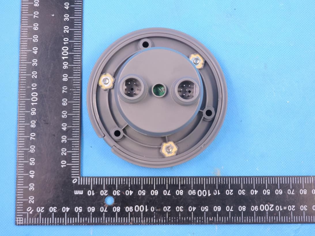
ML6CMSCU
May 28, 2023CMS Control Unit with BLE and SRD
Equipment Class
DTS - Digital Transmission System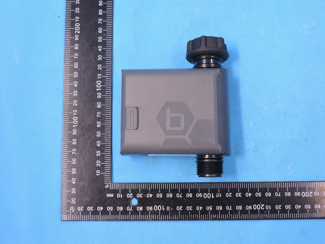
ML6HT25G2
Jul 14, 2022Smart Hose Watering Timer
Equipment Class
DTS - Digital Transmission System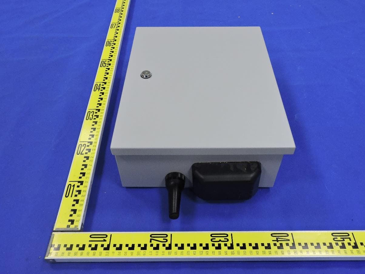
ML6HSC
Jul 10, 2022High Station Count Controller with BLE, 2.4GWIFI, 5GWIFI and LPWAN
Equipment Class
DTS - Digital Transmission System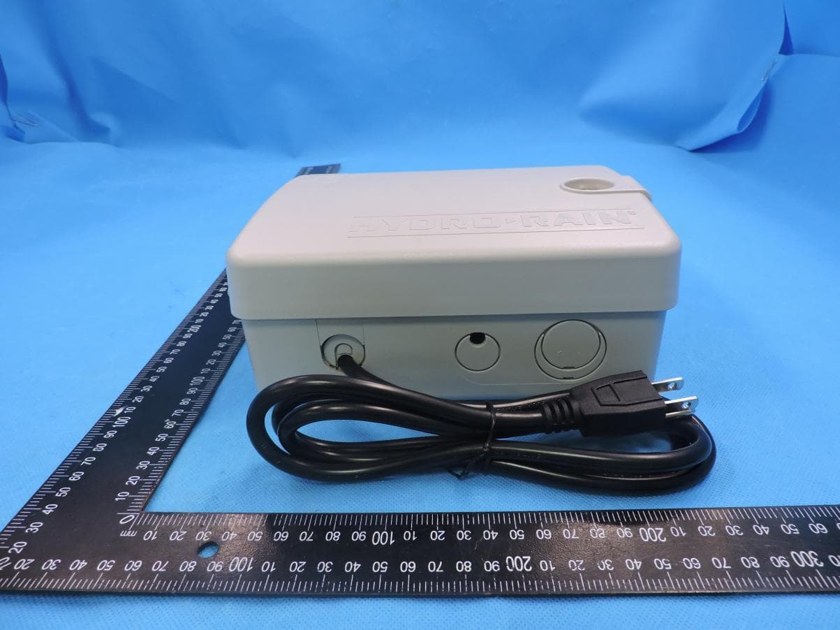
ML6WT25E
Jul 15, 2021B-HYVE Smart WiFi Indoor Sprinkler Timer
Equipment Class
DTS - Digital Transmission System