ML6CMSCUCMS Control Unit with BLE and SRD
Orbit Irrigation Product Inc.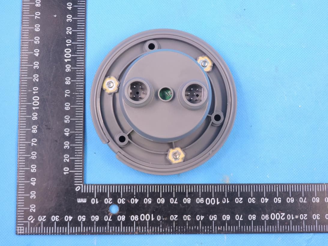
Click to zoom
Application Details
- Equipment Class
- DTS - Digital Transmission System
- Date of Grant
- May 28, 2023
- Application Purpose
- Original Equipment
- Date of Application
- May 27, 2023
- Equipment Note
- CMS Control Unit with BLE and SRD
- Frequency Range
- 2402.00000000 - 2480.00000000
- Country
- United States
Documents & Files
Document Text
Text extracted from the exhibit documents filed with the FCC. Open a document above to read the original.
Users Manual
Contents • Control Unit • Mounting screws • Instruction manual NOTE: For control from remote locations, a B-hyve Cell Module (sold separately) is necessary. Required Tools/Items • 6 AA batteries (Energizer ® or Duracell ® ) • 2.5 in. (64 mm) Hole saw • Drill and driver bits • Phillips screw driver • DC latching solenoid(s) (for valve control) • Phone with B-hyve Pro or B-hyve Ag app installed Components1 PAIR CMS CONTROL UNIT Install the B-hyve Pro or B-hyve Ag app on your smart device Download the B-hyve Pro or B-hyve Ag app from the Apple App Store or Google Play. The app will guide you through setting up your CMS Control Unit. Select a location Preferably, the CMS Control Unit should be mounted on the lid of the valve box containing the valve(s) or flow meter you wish to control/read. Whether mounted to a valve box or a wall (CMS- WM Wall Mount, sold separately), the CMS Control Unit should be mounted as close to the valve(s) or flow meter as possible. Note: CMS Control Unit should be paired with a smart device at the installation location to ensure sufficient wireless signal or cellular strength. Placing the CMS Control Unit inside a valve box rather than mounting it to the valve box lid will diminish your wireless signal. Remove the lid Remove the lid of the CMS Control Unit by unscrewing the three screws on top using a phillips screw driver. Install the batteries (not included) The CMS Control Unit uses six AA batteries. (For best performance and battery life, use Energizer ® or Duracell ® batteries.) Remove the battery tray by sliding the latch to the left. Insert the batteries. Reinsert the battery tray and slide the latch back to the right. NOTE: The CMS Control Unit has non-volatile memory that retains programming when the batteries are removed or drained. Install the B-hyve Pro Cellular Module (sold separately) Remove the rubber lid covering the cellular module compartment. Slide the B-hyve Cellular Module (sold separately) into the compartment until it is securely in place. Connect the CMS Control Unit to the app Open the B-hyve Pro or B-hyve Ag app on your smart device. In the app, go to the device list and tap the “+” button. You will, then, be guided through the set-up process. CONTROL AND MONITORING SYSTEM CMS Control Unit MODEL NO: CMS-CU PART NO: 04400 PN 04400-24 rB Lid Battery Latch Battery Tray Mac ID Pairing/ Reset Button Status Light B-hyve Cellular Module Port Accessory Module Ports Mounting Screws NORTH AMERICA HELP: (888) Hydro-Rain www.hydrorain.com Printers are responsible for meeting print production requirements. Any changes must be approved by Orbit ® . Printed piece must meet designated specifications on this form. © 2014 Orbit Inc. This work is the property of Orbit ® , and cannot be used, reproduced or distributed in any way without their express permission. Dieline PMS 2955 Fold PMS 0000 Product Coverage PMS 0000 Dims./ Callout PMS 0000 ∙ ∙ ∙ ∙ Orbit ® 1.801.299.5555 orbitonline.com Glue FoldedFlatAdditional Information PRINTERS ARE REQUIRED TO MATCH ALL SPECIFIED PMS COLORS. DATE: 04/20/2023 DESIGNER: SMMARKETING: MS SOFTWARE: Adobe Indesign CC ARTWORK No: 04400-24 RB L: W: H: W: H:4.0" 4.0" 20.0" 4.0" 2 INSTALL THE CONTROL UNIT Drill a hole in valve box lid Using a 2.5 in. (64 mm) hole saw, drill a hole in the center of the valve box lid. Mount CMS Control Unit Ensure the lid of the CMS Control Unit is off and place it in the hole. Using a drill with a phillips bit, install the three mounting screws to secure the CMS Control Unit to the valve box lid. Note: Do not attach the lid of the CMS Control Unit until after it has been paired with a mobile device. Accessory Modules may now be connected. 3 INSTALL ACCESSORY MODULES (SOLD SEPARATELY) Ensure the B-hyve Pro or B-hyve Ag app is connected to the CMS Control Unit. Using wire nuts, connect the control wires to a DC latching solenoid or flow meter wires. Remove a cap from one of the CMS Control Unit’s accessory ports. Push the male connector on the accessory module into the port and tighten the connector nut. Open the B-hyve Pro or B-hyve Ag app on your smart device and follow the step-by-step pairing process in the app. SPECIFICATIONS Battery Specifications: CMS Control Unit requires 6 AA Energizer ® or Duracell ® batteries (not included). Warning: Batteries must be removed from the CMS Control Unit before it is scrapped. Rated input: 3.3-5V DC IP67 Rating Temperature Operating Range: Operating: -4-140° F (-20-60° C) Storage & transport: -4-140° F (-20-60° C) Humidity Operating Range: Operating: 0-100% Storage & transport: 0-90% EU & UKCA Declaration of Conformity Pro-Mark, LLC 845 Overland Rd., NSL, UT 84054 USA Declares under our sole responsibility, that the product: CMS Control Unit Complies with the following: European Directives 2014/53/EU and UKCA Radio Equipment Regulations 2017, SI 2017:1206 (as amended by SI 2019:696) with reference to the following standards: ETSI EN & EN 300 220-1 V3.1.1 (2017-02) ETSI EN & EN 300 220-2 V3.2.1 (2018-06) ETSI EN & EN 300 328 V2.2.2 (2019-07) BS EN & EN 50665:2017 ETSI EN & EN 301 489-1 V2.2.3 (2019-11) ETSI EN & EN 301 489-3 V2.1.2 (2021-03) ETSI EN & EN 301 489-17 V3.2.4 (2020-09) BS EN & EN 55032:2015/A11:2020, BS EN IEC & EN IEC 61000- 3-2:2019/A1:2021 BS EN & EN 61000-3-3:2013/A1:2019 BS EN & EN 55035:2017/A11:2020 BS EN & EN 60730-1:2016 BS EN & EN 60730-2-7:2020 FCC & ICID STATEMENT: This device complies with Part 15 of the FCC Rules and Industry Canada license exempt RSS standards. Operation is subject to the following two conditions: (1) This device may not cause harmful interference, and (2) this device must accept any interference received, including interference that may cause undesired operation. FCC Warning: Any changes or modifications not expressly approved by the party responsible for compliance could void the user’s authority to operate this equipment. Note: This equipment has been tested and found to comply with the limits for a Class B dig…
Text truncated - open the document above for the full version.
Attestation Statements
Orbit Irrigation Product Inc. Covered Equipment Certification Attestation Letter 5/6/2023 ATTN.: Reviewing Engineer Orbit Irrigation Product Inc.certifies that the equipment for which authorization is sought is not “covered” equipment prohibited from receiving an equipment authorization pursuant to section 2.903 of the FCC rules. Note: If the equipment for which the applicant seeks authorization is produced by any of the entities identified on the current Covered List, the applicant should include an explanation on why the equipment is not “covered” equipment. Orbit Irrigation Product Inc. certifies that, as of the date of the filing of the application, the applicant is not identified on the Covered List as an entity producing “covered” equipment. Signature: Date: 2023.05.06 Name: Karl Connolly Title: EVP Prod. Dev. Company: Orbit Irrigation Product Inc.
Attestation Statements
Orbit Irrigation Products, LLC 845 North Overland Road North Salt Lake, Utah 84054 Mailing address: PO Box 328 Bountiful, UT 84011-0328 Street address: 845 North Overland Road North Salt Lake, UT 84054 801.299.5555 main line 800.488.6156 toll free www.orbitonline.com U.S. Agent Designation for Service of Process - Certification Attestation Letter 5/6/2023 ATTN.: Reviewing Engineer FCC ID: ML6CMSCU Per section 2.911(d)(7) of the FCC rules, Orbit Irrigation Products, LLC (“the applicant”) will also serve as the agent for service of process for the above referenced FCC ID. Contact Person: Karl Connolly Company Name: Orbit Irrigation Products, LLC FRN No.: 0023422009 Company Address: 845 Overland Rd., North Salt Lake City, Utah 84054 USA Email: [email protected] The above contact person accepts the obligation for service of process. The applicant accepts to maintain an agent for no less than one year after the grantee has terminated all marketing and importation or the conclusion of any Commission-related proceeding involving the equipment. Sincerely, Signature: Date: 2023.05.06 Name: Karl Connolly Title: EVP Prod. Dev. Company: Orbit Irrigation Products, LLC
Cover Letter(s)
Orbit Irrigation Product Inc. Agent Authorization Company: Orbit Irrigation Product Inc. Address: 845 Overland Road, North Salt Lake, Utah 84054 USA Product Name: CMS Control Unit Model Number(s): CMS-CU Product Description: CMS Control Unit with BLE and SRD We authorize MiCOM Labs Inc., 575 Boulder Court, Pleasanton, California 94566, USA, to act on our behalf on all matters concerning the certification of above named equipment. We declare that MiCOM Labs Inc. is allowed to forward all information related to the approval and certification of equipment to the regulatory agencies as required and to discuss any issues concerning the approval application. Any and all acts carried out by MiCOM Labs on our behalf shall have the same effect as acts of our own. Signature: Date: 2023.05.06 Name: Karl Connolly Title: EVP Prod. Dev. Company: Orbit Irrigation Product Inc.
Cover Letter(s)
Orbit Irrigation Product Inc. Office of Engineering Technology Federal Communications Commission 7435 Oakland Mills Road Columbia, MD 21046 USA Date: 2023.05.06 Subject; Request for Confidentiality FCC ID: ML6CMSCU To Whom It May Concern, Pursuant to the provisions of the Commission’s rules Title 47 Sections §0.457 and §0.459, we are requesting the Commission to withhold the following attachment(s) as confidential documents from public disclosure indefinitely. These documents contain detailed system and equipment descriptions and are considered as proprietary information in operation of the equipment. The public disclosure of these documents might be harmful to our company and would give competitors an unfair advantage in the market. Schematic Diagram Block Diagram Parts List Operational Description Tune-up Procedure In additional to above mentioned documents, in order to comply with the marketing regulations in Title 47 CFR §2.803 and the importation rules in Title 47 CFR §2.1204, while ensuring that business sensitive information remains confidential until the actual marketing of newly authorized devices, we request Short Term Confidentiality of the following attachment(s); External Photos Test Setup Photos Internal Photos User Manual For 45 days, pursuant to Public Notice DA 04-1705. OR For 180 days pursuant to KDB 726920 D01. It is our understanding that all measurement test reports, FCC ID label format and correspondence during the certification review process cannot be granted as confidential documents and this information will be available for public review once the grant of equipment authorization is issued. Sincerely, Orbit Irrigation Product Inc. Signature: Date: 2023.05.06 Name: Karl Connolly Title: EVP Prod. Dev. Company: Orbit Irrigation Product Inc.
External Photos
Page 1 of 3 Report No.: STS2211125 APPENDIX-PHOTOGRAPHS OF EUT CONSTRUCTIONAL DETAILS Model: CMS-CU Photo 1 Photo 2 Page 2 of 3 Report No.: STS2211125 Photo 3 Photo 4 Page 3 of 3 Report No.: STS2211125 Photo 5 Photo 6
ID Label/Location Info
Label
Internal Photos
Page 1 of 2 Report No.: STS2211125 APPENDIX-PHOTOGRAPHS OF EUT CONSTRUCTIONAL DETAILS Model: CMS-CU Photo 1 Photo 2 BLE ANTEN NA NA SRD Antenna Page 2 of 2 Report No.: STS2211125 Photo 3
RF Exposure Info
Any reproduction of this document must be done in full. No single part of this document may be reproduced without permission from STS, all test data presented in this report is only applicable to presented test sample. Shenzhen STS Test Services Co., Ltd. A 1/F, Building B, Zhuoke Science Park, No.190 Chongqing Road, HepingShequ, Fuyong Sub-District, Bao’an District, Shenzhen, Guang Dong, China TEL: +86-755 3688 6288 FAX: +86-755 3688 6277 E-mail:[email protected] RADIO TEST REPORT Report No: STS2211125H02 Issued for Orbit Irrigation Products Inc 845N. Overland Road, North Salt Lake, Utah 84054 USA Product Name: CMS Control Unit Brand: Hydro-Rain Model Number: CMS-CU Series Model(s): N/A FCC ID: ML6CMSCU Test Standard: FCC 47CFR §2.1091 S T L A B S Page 2 of 9 Report No.: STS2211125H02 Test Report Certification Applicant’s Name ................. : Orbit Irrigation Products Inc Address ................................. : 845N. Overland Road, North Salt Lake, Utah 84054 USA Manufacturer's Name .......... : GARDENA Inc. Address ................................. : 845N. Overland Road, North Salt Lake, Utah 84054 USA Product Description Product Name ........................ : CMS Control Unit Brand ................................... : Hydro-Rain Model Number ....................... : ... : CMS-CU Series Model(s) ..................... : N/A Standards ............................. : FCC 47CFR §2.1091 447498 D04 Interim General RF Exposure Guidance v01 This report shall not be reproduced except in full, without the written approval of STS, this document only be altered or revised by STS, personal only, and shall be noted in the revision of the document. Date of Test ........................................... : Date of receipt of test item ..................... : 08 Feb. 2023 Date (s) of performance of tests ............. : 08 Feb. 2023 ~ 10 Apr. 2023 Date of Issue .......................................... : 10 Apr. 2023 Test Result.............................................. : Pass Testing Engineer : (Chris Chen) Technical Manager : (Sean she) Authorized Signatory : (Bovey Yang) Page 3 of 9 Report No.: STS2211125H02 TABLE OF CONTENTS 1. GENERAL INFORMATION 5 1.1 GENERAL DESCRIPTION OF THE EUT 5 1.2 TEST FACTORY 5 2. FCC 47CFR §2.1091 REQUIREMENT 6 2.1 TEST STANDARDS 6 2.2 LIMIT 6 2.3 TEST RESULT 9 Page 4 of 9 Report No.: STS2211125H02 Revision History Rev. Issue Date Report No. Effect Page Contents 00 10 Apr. 2023 STS2211125H02 ALL Initial Issue Page 5 of 9 Report No.: STS2211125H02 1. GENERAL INFORMATION 1.1 GENERAL DESCRIPTION OF THE EUT Product Name CMS Control Unit Brand Hydro-Rain Model Number CMS-CU Series Model(s) N/A Model Difference N/A Product Description The EUT is CMS Control Unit. Operation Frequency: BLE: 2402-2480 MHz Other SRD: 125KHz: 903.9-914.9 MHz 500KHz: 903-916.2 MHz 923.3-926.9 MHz Modulation Type: BLE: GFSK Other SRD: LoRa Antenna gain: BLE: 0.5dBi Other SRD: 0.2dBi Antenna Designation: BLE: Ceramic Antenna Other SRD: FPC Antenna Rating Input: 3.3-6V DC, or Battery: 6 Alkaline AA batteries Hardware version number 008 Software version number 1.0 1.2 TEST FACTORY SHENZHEN STS TEST SERVICES CO., LTD Add. : A 1/F, Building B, Zhuoke Science Park, No.190 Chongqing Road, HepingShequ, Fuyong Sub-District, Bao’an District, Shenzhen, Guang Dong, China FCC test Firm Registration Number: 625569 IC test Firm Registration Number: 12108A A2LA Certificate No.: 4338.01 Page 6 of 9 Report No.: STS2211125H02 2. FCC 47CFR §2.1091 REQUIREMENT 2.1 TEST STANDARDS Follow the maximum permissible exposure (MPE) limits specified in 447498 D04 Interim General Radio Frequency Exposure Guidelines v01. The gain of the antenna used in the product was extracted from the supplied antenna data sheet and the maximum total power input to the antenna was also measured. Calculate the distance from the product to the MPE limit by the formula. 2.2 LIMIT For single RF sources (i.e., any single fixed RF source, mobile device, or portable device, as defined in paragraph (b)(2) of this section): A single RF source is exempt if: (A) The available maximum time-averaged power is no more than 1 mW, regardless of separation distance. This exemption may not be used in conjunction with other exemption criteria other than those in paragraph (b)(3)(ii)(A) of Part 1.1307. Medical implant devices may only use this exemption and that in paragraph (b)(3)(ii)(A); (B) Or the available maximum time-averaged power or effective radiated power (ERP), whichever is greater, is less than or equal to the threshold Pth (mW) described in the following formula. This method shall only be used at separation distances (cm) from 0.5 centimeters to 40 centimeters and at frequencies from 0.3 GHz to 6 GHz (inclusive). Pth is given by: Page 7 of 9 Report No.: STS2211125H02 (C) Or using below table and the minimum separation distance (R in meters) from the body of a nearby person for the frequency (f in MHz) at which the source operates, the ERP (watts) is no more than the calculated value prescribed for that frequency. For the exemption in Table 1 to apply, R must be at least λ/2π, where λ is the free-space operating wavelength in meters. If the ERP of a single RF source is not easily obtained, then the available maximum time-averaged power may be used in lieu of ERP if the physical dimensions of the radiating structure(s) do not exceed the electrical length of λ/4 or if the antenna gain is less than that of a half-wave dipole (1.64 linear value). RF Source frequency (MHz) Threshold ERP(watts) 0.3-1.34 1,920 R 2 . 1.34-30 3,450 R 2 /f 2 . 30-300 3.83 R 2 . 300-1,500 0.0128 R 2 f. 1,500-100,000 19.2R 2 . Page 8 of 9 Report No.: STS2211125H02 For multiple RF sources: Multiple RF sources are exempt if: (A) The available maximum time-averaged power of each source is no more than 1 mW and there is a separation distance of two centimeters between any portion of a radiating structure operating and the nearest portion of any other radiating structure in …
Text truncated - open the document above for the full version.
Test Report
2.4GHz Mini Antenna, SMTP/N 2450AT18B100 Detail Specification: Page 1 of 5 *Efficiency based on Johanson's standard evaluation board ±± ±± ±± https://www.johansontechnology.com 4001 Calle Tecate • Camarillo, CA 93012 • TEL 805.389.1166 FAX 805.389.1821 Ver. 4.0 2018 Johanson Technology, Inc. All Rights Reserved Want the layout file? Request it at: https://www.johansontechnology.com/ask-a-question High Frequency Ceramic Solutions Part Number 11/5/2018 Avg. Rad Efficiency* Let us help you with the antenna design, optimization, and tuning! 2450AT18B100 2400 - 2500 76% General Specifications Frequency (MHz) -45 to +125°C -45 to +125°C 3000pcs Return Loss (dB) Impedance Input Power Storage Temperature Operating Temperature Reel Quantity 50 Ω 2 Watts max. (CW) Recommended Storage Conditions of unused product on T&R and period. +5 to +35°C Humidity 45~75%RH 18 months max. Johanson Technology, Inc. reserves the right to make design changes without notice. All sales are subject to Johanson Technology, Inc. terms and conditions. e.g. 2450AT18B100(E or S)100% Tin Packing Style Evaluation Board 2450AT18B100-EB1SMA (see page 2&3 for details) Bulk (loose) T & R Suffix = E or S Suffix = E P/N Suffix Mechanical Dimensions In L 0.1260.0083.200.2 W 0.0630.0081.600.2 T 0.0511.30 +0.1/-0.2+.004/-.008 a 0.0200.0080.500.2 Terminal Configuration Function FEED NC No. 1 2 mm e.g. 2450AT18B100E e.g. 2450AT18B100SSuffix = S Part Number Explanation Peak Gain (dBi typ.) Average Gain (dBi typ.) 0.5 -0.5 9.5 min. ① ② L W a T 2.4GHz Mini Antenna, SMTP/N 2450AT18B100 Detail Specification: Page 2 of 5 https://www.johansontechnology.com 4001 Calle Tecate • Camarillo, CA 93012 • TEL 805.389.1166 FAX 805.389.1821 Ver. 4.0 2018 Johanson Technology, Inc. All Rights Reserved High Frequency Ceramic Solutions 11/5/2018 Mounting Considerations 1: Evaluation Board Johanson Technology, Inc. reserves the right to make design changes without notice. All sales are subject to Johanson Technology, Inc. terms and conditions. To order a pre‐tuned 50Ω EVB with a female SMA connector click here: https://www.johansontechnology.com/request‐a‐sample Reference p/n: 2450AT18B100‐EB1SMA GND NO GND Units in mm ) ) 13.5 6.5 39.5 6.5 50Feed Line Antenna 4 ) Matching Component JTI P/Ns: L-14C2N7JV4 L-14C2N2JV4 * 2.6 4.2 1.6 1.9 0.4 2.7nH 1.2pF 3.3nH JTI P/N for Matching Circuit: Capacitor (1.2pF): 500R07S1R2BV4T Inductor (2.7nH): L-07C2N7SV6T Inductor (3.3nH): L-07C3N3SV6T *Line width should be designed to provied 50Ω impedance 2.4GHz Mini Antenna, SMTP/N 2450AT18B100 Detail Specification: Page 3 of 5 https://www.johansontechnology.com 4001 Calle Tecate • Camarillo, CA 93012 • TEL 805.389.1166 FAX 805.389.1821 Ver. 4.0 2018 Johanson Technology, Inc. All Rights Reserved High Frequency Ceramic Solutions 11/5/2018 Mounting Considerations 1: Typical Electrical Performance (T=25°C) Johanson Technology, Inc. reserves the right to make design changes without notice. All sales are subject to Johanson Technology, Inc. terms and conditions. Would you like the antenna layout? Have antenna tuning issues? Please contact us if you have any questions regarding the implementation of this antenna in your PCB's layout. We'll be happy to guide you to maximize the antenna's performance. Contact our applications engineers at: https://www.johansontechnology.com/ask‐a‐question 2.4GHz Mini Antenna, SMTP/N 2450AT18B100 Detail Specification: Page 4 of 5 https://www.johansontechnology.com 4001 Calle Tecate • Camarillo, CA 93012 • TEL 805.389.1166 FAX 805.389.1821 Ver. 4.0 2018 Johanson Technology, Inc. All Rights Reserved High Frequency Ceramic Solutions 11/5/2018 Mounting Considerations 1: Antenna Performance Johanson Technology, Inc. reserves the right to make design changes without notice. All sales are subject to Johanson Technology, Inc. terms and conditions. θ +Z (θ= 0°) +Y (θ= 90°) -Y -Z Typical 2D radiation patterns @ 2.44GHz YZ‐plane XZ‐plane XY‐plane Z Y Z X X Y φ +X (φ= 0°) -X +Y (φ= 90°) -Y θ +Z (θ= 0°) +X (θ= 90°) -X -Z 2.4GHz Mini Antenna, SMTP/N 2450AT18B100 Detail Specification: Page 5 of 5 https://www.johansontechnology.com 4001 Calle Tecate • Camarillo, CA 93012 • TEL 805.389.1166 FAX 805.389.1821 Ver. 4.0 2018 Johanson Technology, Inc. All Rights Reserved https://www.johansontechnology.com/rohs-compliance Need help designing the antenna in? Use our antenna design services! https://www.johansontechnology.com/ipc-antenna-services We provide 2 free layout reviews and if you need us to tune and characterize the antenna on your product (inside our anechoic chamber) we can do that too. Small lab fee may apply. High Frequency Ceramic Solutions Antenna tuning, optimization, and validation services: For more antennas and to download measured S-parameters, go to: 11/5/2018 Johanson Technology, Inc. reserves the right to make design changes without notice. All sales are subject to Johanson Technology, Inc. terms and conditions. RoHS Compliance Soldering Information For layout review contact our Applications Team at: MSL Info Packaging information https://www.johansontechnology.com/ipc-antenna-services https://www.johansontechnology.com/antennas https://www.johansontechnology.com/ipcsoldering-profile https://www.johansontechnology.com/msl-rating https://www.johansontechnology.com/tape-reel-packaging https://www.johansontechnology.com/ask-a-question
Test Report
Any reproduction of this document must be done in full. No single part of this document may be reproduced without permission from STS, all test data presented in this report is only applicable to presented test sample. Shenzhen STS Test Services Co., Ltd. A 1/F, Building B, Zhuoke Science Park, No.190 Chongqing Road, HepingShequ, Fuyong Sub-District, Bao’an District, Shenzhen, Guang Dong, China TEL: +86-755 3688 6288 FAX: +86-755 3688 6277 E-mail:[email protected] RADIO TEST REPORT Report No.:STS2211125W05 Issued for Orbit Irrigation Products Inc 845N. Overland Road, North Salt Lake, Utah 84054 USA Product Name: CMS Control Unit Brand: Hydro-Rain Model Number: CMS-CU Series Model(s): N/A FCC ID: ML6CMSCU IC: 3330A-CMSCU Test Standard: FCC Part 15.247 RSS-247 Issue 2, February 2017 RSS-Gen Issue 5, Amendment 2, February 2021 S T L A B S Page 2 of 81 Report No.: STS2211125W05 TEST RESULT CERTIFICATION Applicant’s Name ................. : Orbit Irrigation Products Inc Address ................................. : 845N. Overland Road, North Salt Lake, Utah 84054 USA Manufacturer's Name .......... : GARDENA Inc. Address ................................. : 845N. Overland Road, North Salt Lake, Utah 84054 USA Product Description Product Name ....................... : CMS Control Unit Brand ................................... : Hydro-Rain Model Number ....................... : ... : CMS-CU Series Model(s) ..................... : N/A Test Standards ..................... : FCC Part15.247 RSS-247 Issue 2, February 2017 RSS-Gen Issue 5, Amendment 2, February 2021 Test Procedure ...................... : ANSI C63.10-2013 This device described above has been tested by STS, the test results show that the equipment under test (EUT) is in compliance with the FCC/IC requirements. And it is applicable only to the tested sample identified in the report. This report shall not be reproduced except in full, without the written approval of STS, this document may be altered or revised by STS, personal only, and shall be noted in the revision of the document. Date of Test ........................................... : Date of receipt of test item ..................... : 08 Feb. 2023 Date (s) of performance of tests ............. : 08 Feb. 2023 ~ 10 Apr. 2023 Date of Issue .......................................... : 10 Apr. 2023 Test Result.............................................. : Pass Testing Engineer : (Chris Chen) Technical Manager : (Sean she) Authorized Signatory : (Bovey Yang) Page 3 of 81 Report No.: STS2211125W05 Table of Contents 1. SUMMARY OF TEST RESULTS 7 1.1 TEST FACTORY 8 1.2 MEASUREMENT UNCERTAINTY 8 2. GENERAL INFORMATION 9 2.1 GENERAL DESCRIPTION OF THE EUT 9 2.2 DESCRIPTION OF THE TEST MODES 11 2.3 TEST SOFTWARE AND POWER LEVEL 11 2.4 BLOCK DIAGRAM SHOWING THE CONFIGURATION OF SYSTEM TESTED 12 2.5 DESCRIPTION OF NECESSARY ACCESSORIES AND SUPPORT UNITS 13 2.6 EQUIPMENTS LIST 14 3. EMC EMISSION TEST 15 3.1 CONDUCTED EMISSION MEASUREMENT 15 3.2 TEST PROCEDURE 16 3.3 TEST SETUP 16 3.4 EUT OPERATING CONDITIONS 16 3.5 TEST RESULTS 17 4. RADIATED EMISSION MEASUREMENT 18 4.1 RADIATED EMISSION LIMITS 18 4.2 TEST PROCEDURE 21 4.3 TEST SETUP 22 4.4 EUT OPERATING CONDITIONS 22 4.5 FIELD STRENGTH CALCULATION 23 4.6 TEST RESULTS 24 5. CONDUCTED SPURIOUS & BAND EDGE EMISSION 37 5.1 LIMIT 37 5.2 TEST PROCEDURE 37 5.3 TEST SETUP 37 5.4 EUT OPERATION CONDITIONS 37 5.5 TEST RESULTS 37 6. POWER SPECTRAL DENSITY TEST 38 6.1 LIMIT 38 6.2 TEST PROCEDURE 38 6.3 TEST SETUP 38 Page 4 of 81 Report No.: STS2211125W05 Table of Contents 6.4 EUT OPERATION CONDITIONS 38 6.5 TEST RESULTS 38 7. BANDWIDTH TEST 39 7.1 LIMIT 39 7.2 TEST PROCEDURE 39 7.3 TEST SETUP 39 7.4 EUT OPERATION CONDITIONS 39 7.5 TEST RESULTS 39 8. PEAK OUTPUT POWER TEST 40 8.1 LIMIT 40 8.2 TEST PROCEDURE 40 8.3 TEST SETUP 41 8.4 EUT OPERATION CONDITIONS 41 8.5 TEST RESULTS 41 9. ANTENNA REQUIREMENT 42 9.1 STANDARD REQUIREMENT 42 9.2 EUT ANTENNA 42 10. FREQUENCY STABILITY 43 10.1 LIMITS OF FREQUENCY STABILITY MEASUREMENT 43 10.2 TEST PROCEDURE 43 10.3 TEST RESULT 43 1M PHY 43 2M PHY 44 APPENDIX 1-TEST DATA 45 1. DUTY CYCLE 45 2. MAXIMUM AVERAGE CONDUCTED OUTPUT POWER 49 3. MAXIMUM PEAK CONDUCTED OUTPUT POWER 53 4. -6DB BANDWIDTH 57 5. OCCUPIED CHANNEL BANDWIDTH 61 6. MAXIMUM POWER SPECTRAL DENSITY LEVEL 65 7. BAND EDGE 69 Page 5 of 81 Report No.: STS2211125W05 Table of Contents 8. CONDUCTED RF SPURIOUS EMISSION 74 APPENDIX 2- EUT TEST PHOTO 81 Page 6 of 81 Report No.: STS2211125W05 Revision History Rev. Issue Date Report NO. Effect Page Contents 00 10 Apr. 2023 STS2211125W05 ALL Initial Issue Page 7 of 81 Report No.: STS2211125W05 1. SUMMARY OF TEST RESULTS Test procedures according to the technical standards: KDB 558074 D01 15.247 Meas Guidance v05r02. FCC Part 15.247,Subpart C RSS-247 Issue 2 Standard Section Test Item Judgment Remark 15.207 RSS-Gen 8.8 Conducted Emission N/A -- 15.247 (a)(2) RSS-Gen 6.7 RSS-247 5.2 (a) 6dB&99% Bandwidth PASS -- 15.247 (b)(3) RSS-247 5.4 (d) Output Power PASS -- 15.209 RSS-Gen 8.9/8.10 Radiated Spurious Emission PASS -- 15.247 (d) RSS-247 5.5 RSS-Gen 8.9/8.10 Conducted Spurious & Band Edge Emission PASS -- 15.247 (e) RSS-247 5.2 (b) Power Spectral Density PASS -- 15.205 RSS-Gen 8.9/8.10 Restricted bands of operation PASS -- Part 15.247(d)/ Part 15.209(a) RSS-247 5.5 RSS-Gen 8.9/8.10 Band Edge Emission PASS -- 15.203 RSS-Gen 6.8 Antenna Requirement PASS -- RSS-Gen 6.11/8.11 Frequency Stability PASS -- NOTE: (1) ‘N/A’ denotes test is not applicable in this Test Report. (2) All tests are according to ANSI C63.10-2013. Page 8 of 81 Report No.: STS2211125W05 1.1 TEST FACTORY SHENZHEN STS TEST SERVICES CO., LTD Add. : A 1/F, Building B, Zhuoke Science Park, No.190 Chongqing Road, HepingShequ, Fuyong Sub-District, Bao’an District, Shenzhen, Guang Dong, China FCC test Firm Registration Number: 625569 IC test Firm Registration Number: 12108A A2LA Certificate No.: 4338.01 1.2 MEASUREMENT UNCERTAINTY The reported uncertainty of measur…
Text truncated - open the document above for the full version.
Test Setup Photos
Page 1 of 1 FCC ID: ML6CMSCU IC: 3330A-CMSCU DTS&DXX Setup Photo Model Number: CMS-CU DTS&DXX radiation L DTS&DXX radiation H
Contact Information
Applicant
Karl Connolly(EVP Product Development)
Technical Contact
Test Firm
SHENZHEN STS TEST SERVICES CO.,LTD.Bovey Yang
[email protected]+86 755-36886288
Technical Specifications
| # | Rule Parts | Frequency Range | Power Output |
|---|---|---|---|
| 1 | 15C | 2.40 GHz - 2.48 GHz | 1.53 mW |
Other Applications from Orbit Irrigation Product Inc.

ML6HT25ASR
Mar 23, 2024Hose Faucet Timer
Equipment Class
DTS - Digital Transmission System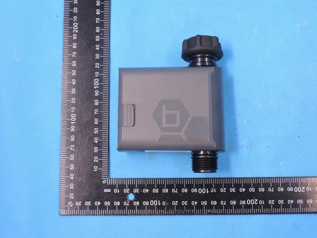
ML6HT25G2
Jul 14, 2022Smart Hose Watering Timer
Equipment Class
DTS - Digital Transmission System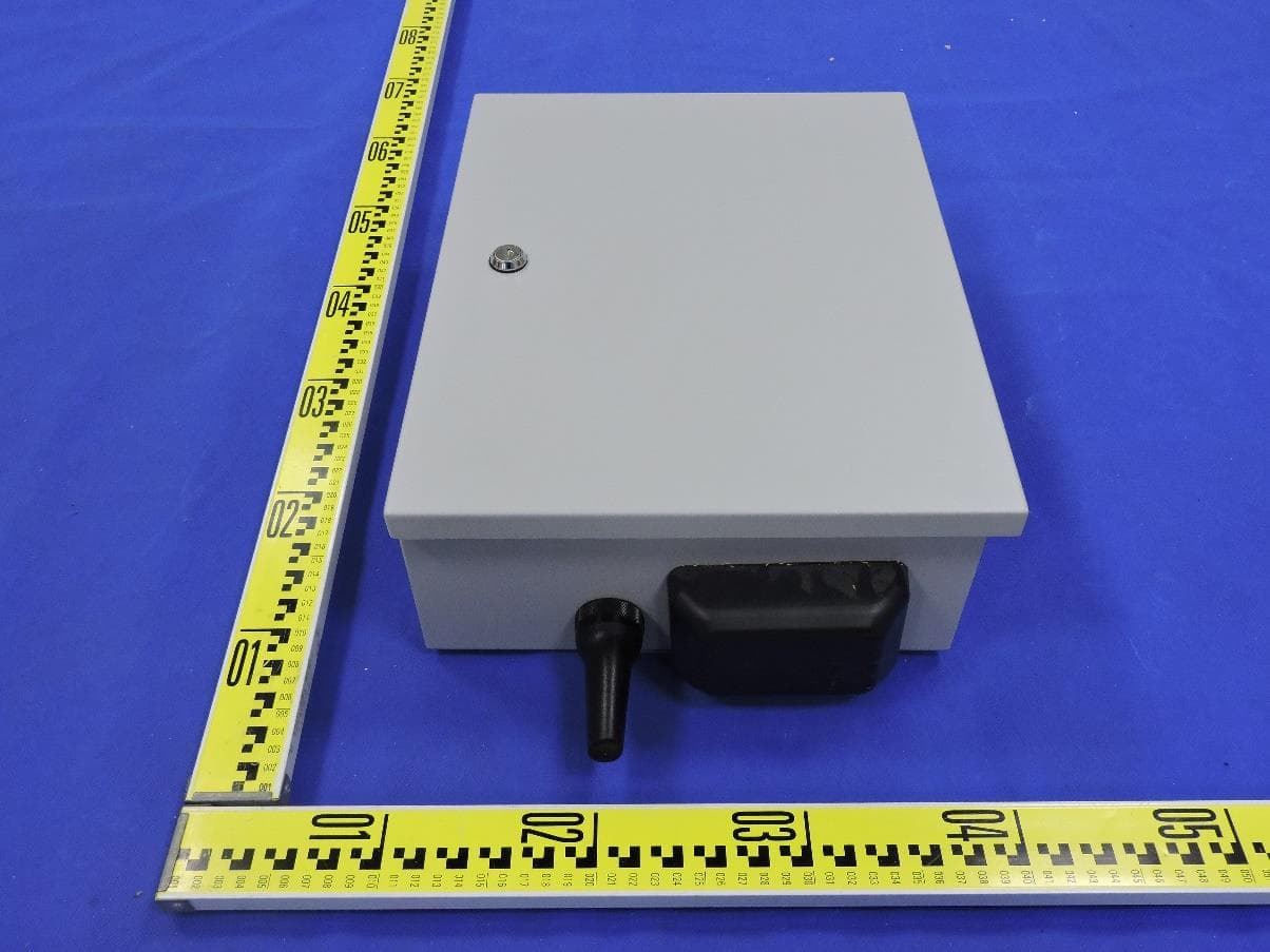
ML6HSC
Jul 10, 2022High Station Count Controller with BLE, 2.4GWIFI, 5GWIFI and LPWAN
Equipment Class
DTS - Digital Transmission System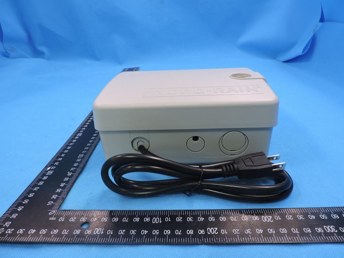
ML6WT25E
Jul 15, 2021B-HYVE Smart WiFi Indoor Sprinkler Timer
Equipment Class
DTS - Digital Transmission System
ML6-25010-11X
May 23, 2021Industrial Gateway
Equipment Class
DTS - Digital Transmission System