ML6WT15ZBTRX12Triple Program Outdoor Water Timer with Zigbee Module
Orbit Irrigation Product Inc.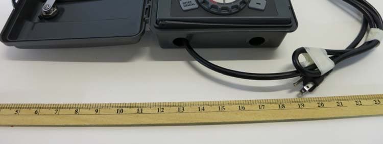
Click to zoom
Application Details
- Equipment Class
- DTS - Digital Transmission System
- Date of Grant
- Nov 04, 2014
- Application Purpose
- Original Equipment
- Date of Application
- Nov 04, 2014
- Equipment Note
- Triple Program Outdoor Water Timer with Zigbee Module
- Frequency Range
- 2405.00000000 - 2480.00000000
- Country
- United States
Documents & Files
Document Text
Text extracted from the exhibit documents filed with the FCC. Open a document above to read the original.
Users Manual
Do not connect to power source until after wiring valves to controller RESET PROGRAM RAIN DELAY AUTO OFF SET CLOCK SET DATE BUDGET HOW OFTEN RUN TIME START TIME PN 27396-24 rD Model 27396 Or 1. SELECT LOCATION AUTO OFF SET CLOCK SET DAY BUDGET HOW OFTEN RUN TIME START TIME For detailed instructions on outdoor wiring, please download the full manual “Outdoor Swing Panel Controller” at www.orbitonline.com Warning: Check state and local codes. Orbit recommends using a licensed electrical contractor for outdoor wiring of controller. Indoor Outdoor Clean, dry, and out of direct sunlight Allow 9 inch clearance for the swing door Pair Controller with Iris ® Testing Communication with Iris ® AUTO - Watering mode SET CLOCK - Set calendar and clock time SET DATE - Year, Month, and Day START TIME - Set time to begin watering RUN TIME - Set watering duration for each station HOW OFTEN - Set frequency of watering days BUDGET - Adjust overall watering as a percentage O FF - Turn all stations off Dial Position Function: 4. CONNECT VALVE WIRE TO TERMINAL 7. CONNECT CONTROLLER TO IRIS ® HOME MANAGEMENT SYSTEM Station 1 Push tab upward to release wire Strip wire Push in Only connect one valve to each terminal (station) 1 1 4 5 1 2 2 3 Set Auto Mode 6 Turn dial to AUTO—you have programmed your controller! 2. MOUNT CONTROLLER MOUNTING TEMPLATE GABARIT D`INSTALLATION GUIA DE COLGAR 4.17” (106mm) Use included mounting template to mark screw locations. Hang controller on screw using keyhole. Level Screw through one of the pre-formed mounting holes. To Controller Wire Nut Solenoid Common Wire Valve Connect one of the two wires from each valve to the common wire leading to the controller (usually white). Connect the other wire from each valve to one of the colored wires leading to the controller. 3. CONNECT SPRINKLER VALVES TO CONTROLLER WIRES 5. ACTIVATE BATTERY 6. CONNECT CONTROLLER TO POWER SOURCE PROGRAM RAIN DELAY HOW OFTEN RUN TIME START TIME Remove plastic strip to activate battery Connect to power Install the controller as shown in the previous steps. Log into your Iris ® account at www.lowes.com/iris using a computer. Follow the instructions in the"Add Device" section of the Iris ® website. Turn the dial to ‘AUTO’ This sprinkler controller is designed to work with the Lowe's Iris ® home management system (Iris ® Smart Hub required). Once connected to Iris ® , you can program, operate, and monitor your controller from anywhere using your smart phone, tablet, or computer. Learn more by visiting www.lowes.com/iris. (This controller can also be used as a standalone sprinkler controller without connecting to Iris ® . See the MANUAL CONTROLLER OPERATION WITHOUT IRIS ® section.) 12-STATION SPRINKLER CONTROLLER QUICK START GUIDE REQUIRED TOOLS: Phillips Screwdriver Wire Strippers Note: The quick start guide is intended to help you get up and running with your new Orbit ® Controller. It includes basic installation, programming and Iris ® connection help. For more information about Iris ® , please visit www.lowes.com/iris. For additional manual programming instructions, please download the full manual “Outdoor Swing Panel Controller” at www.orbitonline.com 9. ADDITIONAL FEATURES RAIN DELAY • Turn dial to AUTO and Press the [RAIN DELAY] button. • Push the [+/-] to select 24, 48 or 72 hours. • Press [ENTER] to begin. • Press [CLEAR] to cancel the rain delay. MANUAL WATERING Your controller has the ability to allow you to manually water with- out disturbing the preset program. To Run all stations at the pre-programed duration • Turn the dial to AUTO. • Press the [MANUAL] button. Display will show A B and ALL. • Press [ENTER] (or wait a few seconds) to begin manual watering. All stations will water consecutively for their programmed duration. To Run a specific station for specified time • Turn the dial to AUTO. • Press the [MANUAL] button. • Press the [ / ] buttons until desired station number appears. • Press the [+/–] to enter the desired duration. • Press [ENTER] (or wait a few seconds) to begin manual watering. To stop Manual Watering press [CLEAR]. Note: After the [MANUAL] button has been pushed, if a selection is not made within 5 seconds all stations and programs will begin watering using the programmed RUN TIMES. If no RUN TIMES have been set, nothing will happen and the display will return to the time of day. BACKUP BATTERY Your controller requires a CR2032 Lithium battery to maintain your program in case of an AC power loss. Tip: The Battery should be replaced every year, to avoid loss of programming. Note: Used up or dead batteries must be removed from the control- ler and disposed of properly. A battery alone will not operate the valves in your sprinkling system nor will it connect to IRIS with battery power alone. The sprinkler controller transformer must be connected to an AC line voltage source. For instructions on “Water Budgeting”, connecting the controller to a “Pump Start” relay, replacing the “Backup Battery” or for installing your controller outdoor, please download the full manual “Outdoor Swing Panel Controller” at www.orbitonline.com 8. MANUAL CONTROLLER OPERATION WITHOUT IRIS ® Set Current Time (e.g. pacific, mountain standard) 1 Turn dial to set clock enter current time (+/-) Set Date 2 SET DATE • Turn dial to SET DATE to enter the Year, Month and Day. • Use the (+/-) button to select the Year. • Press [ENTER] to advance to Month and Day. Pre-formed mounting holes Wall No. 8 Screw ⅛" Keyhole Indoor RESET PROGRAM RAIN DELAY AUTO OFF SET CL OCK SET DAY BUDGET HOW OFTEN RUN TIME START TIME Outdoor Warning: See complete manual for outdoor wiring instructions at www.orbitonline.com When the controller is first connected to power, it will automatically attempt to connect to Iris. The wireless icon will flash until the controller is paired with iris. Once paired, the wireless icon will remain solid and the words 'SMART MODE' will appear on screen. Important notes about using the controller while …
Text truncated - open the document above for the full version.
Cover Letter(s)
Jeannie Clement
Cover Letter(s)
U.S. Mail P.O. Box 328 Bountiful, Utah 84011-0328 Street Address 845 North Overland Road North Salt Lake, Utah 84054 801-299-5555 (Phone) 801-299-5549 (Fax) www.orbitonline.com Federal Communications Commission Authorization and Evaluation Division Confidentiality Request regarding application for certification of FCC ID: ML6WT15ZBTRX12 Pursuant to Sections 47 CRF 0.457(d) of the Commission’s Rules, we hereby request confidential treatment of information accompanying this application as outlined below: Exhibit Type Confidentiality for the following: Block Diagram Schematics BOM (Bill of Materials) Theory of Operations Detailed Operational/Functional Description The above materials contain trade secrets and proprietary information not customarily released to the public. The public disclosure of these materials may be harmful to the applicant and provide unjustified benefits to its competitors. The applicant understands that pursuant to Section 0.457 of the Rules, disclosure of this application and all accompanying documentation will not be made before the date of the Grant for this application. Sincerely, Jeannie Clement Executive Vice President
External Photos
INTERTEK TESTING SERVICES External Photos FCC ID: ML6WT15ZBTRX12 IC: 4450A-WT15ZBTRX12 external photos - 1 of 2 HK14010355 Job Number HK14010355 Job Number INTERTEK TESTING SERVICES External Photos FCC ID: ML6WT15ZBTRX12 IC: 4450A-WT15ZBTRX12 external photos - 2 of 2 Job Number HK14010355
Internal Photos
INTERTEK TESTING SERVICES Internal photos FCC ID: ML6WT15ZBTRX12 IC: 4450A-WT15ZBTRX12 internal photos - 1 of 7 Main Unit assembly Base unit Main PCB top side INTERTEK TESTING SERVICES Internal photos FCC ID: ML6WT15ZBTRX12 IC: 4450A-WT15ZBTRX12 internal photos - 2 of 7 Base unit Main PCB bottom side Zigbee PCB and Antenna INTERTEK TESTING SERVICES Internal photos FCC ID: ML6WT15ZBTRX12 IC: 4450A-WT15ZBTRX12 internal photos - 3 of 7 Base unit Main PCB top side 2 Zigbee PCB Top side INTERTEK TESTING SERVICES Internal photos FCC ID: ML6WT15ZBTRX12 IC: 4450A-WT15ZBTRX12 internal photos - 4 of 7 Zigbee PCB Bottom side Main Unit assembly 2 INTERTEK TESTING SERVICES Internal photos FCC ID: ML6WT15ZBTRX12 IC: 4450A-WT15ZBTRX12 internal photos - 5 of 7 Switch board PCB top side Switch board PCB top side 2 INTERTEK TESTING SERVICES Internal photos FCC ID: ML6WT15ZBTRX12 IC: 4450A-WT15ZBTRX12 internal photos - 6 of 7 Switch Board bottom side Capacitor board PCB top side INTERTEK TESTING SERVICES Internal photos FCC ID: ML6WT15ZBTRX12 IC: 4450A-WT15ZBTRX12 internal photos - 7 of 7 Capacitor board PCB bottom side
RF Exposure Info
INTERTEK TESTING SERVICES FCC ID: ML6WT15ZBTRX12 RF exposure - 1 of 1 For Maximum Permissible Exposure (MPE) evaluation of the unit, the maximum power density at 20 cm from this mobile transmitter shall be less than the General Population / Uncontrolled MPE limit in OET Bulletin 65 and meet the requirement listed in KDB447498. For the 2.4GHz Triple Program outdoor water timer with Zigbee module of tested model: 27396, the measured powers among all the measured channels were within its production tolerance: +0 dBm (Minimum) and +10.5 dBm (Maximum).The antenna gain of 27396 is 0 dBi = 1.00 (num gain) and its maximum source-based time-averaging duty factor is 100.0% (1/1). From these data and its operating configuration – Mobile device, the exposed power density at a distance (R) of 20cm from the center of radiation of the antenna can be calculated according to OET Bulletin 65 as follow: The Conducted Power = 10.5 dBm = 11.22 mW The Conducted Power source-based time-averaging output power = (11.22 * 1.000) mW = 11.22 mW The power density at 20cm = 11.22 *1.00/ 4πR 2 = 0.0022 mW cm -2 In the frequency range of 1,500 - 100,000MHz, the MPE limit is 1.0 mWcm -2 for general population and uncontrolled exposure. As the measured power density at 20cm from the transmitter is lower than the MPE limit, the compliance to the MPE limit can be ensured by indicating the minimum 20cm separation between the transmitter's radiating structures and body of the user or nearby persons. The following RF exposure statement is proposed to be included in the user manual: “ FCC RF Radiation Exposure Statement Caution: To maintain compliance with the FCC’s RF exposure guidelines, place the unit at least 20cm from nearby persons.”
Test Report
lssuing Laboratory: lnteftek Testing Services Hong Kong Limited liong Kong Acorod¡tal¡on Servlce (HKAS) has accrodited thls laborelory under.the Hong Kong Laboralory Accreditalion Scheme (HOKLAS) for sp€clt¡c leborá'rory activllies as lislod ¡n tho HOKLAS dlrectory ol occred¡ted labofatories, Ths rfsults shown in this report wer€ dsterrnlnod by thls labo¡.alory ln accordanc€ with its teims of ôÇcrodltation. TEST REPORT Report Number: 1 4010355HKG-001 Application for Original Grant of 47 CFR Part 15 Certification ïriple Program outdoor water Timer with Zigbee Modure FCC lD: MLGWTISZBTRX12 Prepared and Checked by: Kwok Yeung, Kenneth Approved by: Tho test reporl only allows to be revlsed withln the r€tsntlon perlod unlees further standafd or the roqulrement was noticed.Thls report ls for the exclusive use of lnterlek's Cliont and ls provlded putsuant lo the agreomeht between lnterlek and its Cllent, lntertek's responslblllly and liabllity are limited to lhe terms and condltlons of thã agreement, lnterl€k s66um€8 no liability to gny pafy, other than lo lhe Cllent in accordance with the agreemsnl, lor ãny lose, expense or damage occasloned by the use of this report. Only the Client is authorlzed lo perml[copylng or dlstrlòutlon of tÉls reporl and thãn only. in its antirely. Any use of the lnterlek nam6 or one of lts marks for the sale or sdvertlsement of the teóled malgrlal, product or service must llrst be approved ín wrltlng by lntertek. The observalions and lest results ln thts report are rêlsvant only to the semPle tested. This reporl by itself does not imply that the materlal, product, or serylce ls oi has ever been under an lntertek cerlification program. Chan Chi Hung, Terry Supervisor June 6,2014 , t) ¡- lntertok Teeting Servlces Hong Kong Ltd. 2/F., Gårmsnl Contr€, 576 Castls P6ak Road, Kowloon, Hong Kong, T€l: (852) 2173 8088 Fax: (852) 2785 5487 Webslto: www.hk.lntertei-eilss¡ Issuing Laboratory: Intertek Testing Services Hong Kong Limited Hong Kong Accreditation Service (HKAS) has accredited this laboratory under the Hong Kong Laboratory Accreditation Scheme (HOKLAS) for specific laboratory activities as listed in the HOKLAS directory of accredited laboratories. The results shown in this report were determined by this laboratory in accordance with its terms of accreditation. Test Report Number: 14010355HKG-001 Page 1 of 45 FCC ID: ML6WT15ZBTRX12 Intertek Testing Services Hong Kong Ltd. 2/F., Garment Centre, 576 Castle Peak Road, Kowloon, Hong Kong. Tel: (852) 2173 8888 Fax: (852) 2785 5487 Website: www.hk.intertek-etlsemko.com GENERAL INFORMATION Applicant Name: Orbit Irrigation Product Inc. Applicant Address: 845N Overland Road, North Salt Lake, Utah 84054 USA FCC Specification Standard: FCC Part 15, October 1, 2012 Edition FCC ID: ML6WT15ZBTRX12 FCC Model(s): 27396 Type of EUT: Digital Transmission System Description of EUT: Triple Program Outdoor Water Timer with Zigbee Module Serial Number: N/A Sample Receipt Date: January 09, 2014 Date of Test: February 07-17, 2014 Report Date: June 6, 2014 Environmental Conditions: Temperature: +10 to 40°C Humidity: 10 to 90% Issuing Laboratory: Intertek Testing Services Hong Kong Limited Hong Kong Accreditation Service (HKAS) has accredited this laboratory under the Hong Kong Laboratory Accreditation Scheme (HOKLAS) for specific laboratory activities as listed in the HOKLAS directory of accredited laboratories. The results shown in this report were determined by this laboratory in accordance with its terms of accreditation. Test Report Number: 14010355HKG-001 Page 2 of 45 FCC ID: ML6WT15ZBTRX12 Intertek Testing Services Hong Kong Ltd. 2/F., Garment Centre, 576 Castle Peak Road, Kowloon, Hong Kong. Tel: (852) 2173 8888 Fax: (852) 2785 5487 Website: www.hk.intertek-etlsemko.com Table of Contents 1.0 Summary of Test Results.......................................................................................... 4 1.1 Statement of Compliance .......................................................................................... 4 2.0 General Description................................................................................................... 6 2.1 Product Description ................................................................................................... 6 2.2 Test Methodology...................................................................................................... 6 2.3 Test Facility ...............................................................................................................6 3.0 System Test Configuration........................................................................................ 8 3.1 Justification ...............................................................................................................8 3.2 EUT Exercising Software .......................................................................................... 9 3.3 Details of EUT and Description of Accessories ....................................................... 10 3.4 Measurement Uncertainty ....................................................................................... 10 4.0 Test Results.............................................................................................................. 12 4.1 Maximum Conducted Output Power at Antenna Terminals ..................................... 12 4.2 Minimum 6dB RF Bandwidth................................................................................... 15 4.3 Maximum Power Spectral Density........................................................................... 18 4.4 Out of Band Conducted Emissions.......................................................................... 21 4.5 Field Strength Calculation ....................................................................................... 34 4.6 Transmitter Radiated Emissions in Restricted Bands and Spurious Emissions ....... 35 4.6.1 Radiated Emission Configuration Photograph ............…
Text truncated - open the document above for the full version.
Test Setup Photos
INTERTEK TESTING SERVICES The Worst Case Configuration Photographs - Mode: Transmission mode FCC ID: ML6WT15ZBTRX12 IC: 4450A-WT15ZBTRX12 config photos (radiated emission) - 1 of 1 Radiated Emission Radiated Emission 27396 HK14010355 A5 B Front View Radiated Emission 27396 HK14010355 A B5 Rear View INTERTEK TESTING SERVICES The Worst Case Configuration Photographs - Mode: Transmission mode FCC ID: ML6WT15ZBTRX12 IC: 4450A-WT15ZBTRX12 config photos (conducted emission) - 1 of 2 Conducted Emission Front View Right Side View INTERTEK TESTING SERVICES The Worst Case Configuration Photographs - Mode: Transmission mode FCC ID: ML6WT15ZBTRX12 IC: 4450A-WT15ZBTRX12 config photos (conducted emission) - 2 of 2 Conducted Emission Left Side View
Contact Information
Applicant
Karl Connolly(EVP Product Development)
Technical Contact
Intertek Testing Services Hong Kong Ltd.Terry Chan
[email protected](852) 2173 8503
2/F., Garment Centre, · Kowloon · Hong Kong
Non-Technical Contact
Intertek Testing Services Hong Kong Ltd.Terry Chan
[email protected](852) 2173 8503
Test Firm
Intertek Testing Services Hong Kong Ltd.Billy Chow
Technical Specifications
| # | Rule Parts | Frequency Range | Power Output |
|---|---|---|---|
| 1 | 15C | 2.40 GHz - 2.48 GHz | 1.86 mW |
Other Applications from Orbit Irrigation Product Inc.

ML6HT25ASR
Mar 23, 2024Hose Faucet Timer
Equipment Class
DTS - Digital Transmission System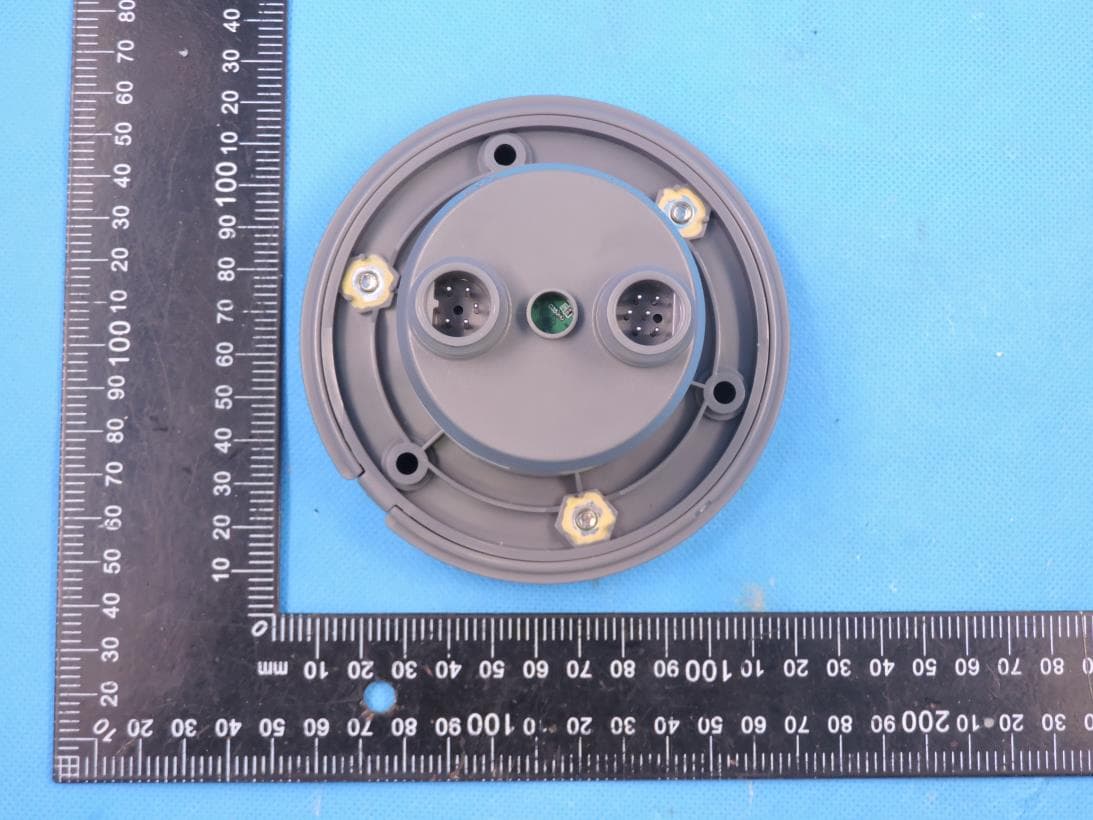
ML6CMSCU
May 28, 2023CMS Control Unit with BLE and SRD
Equipment Class
DTS - Digital Transmission System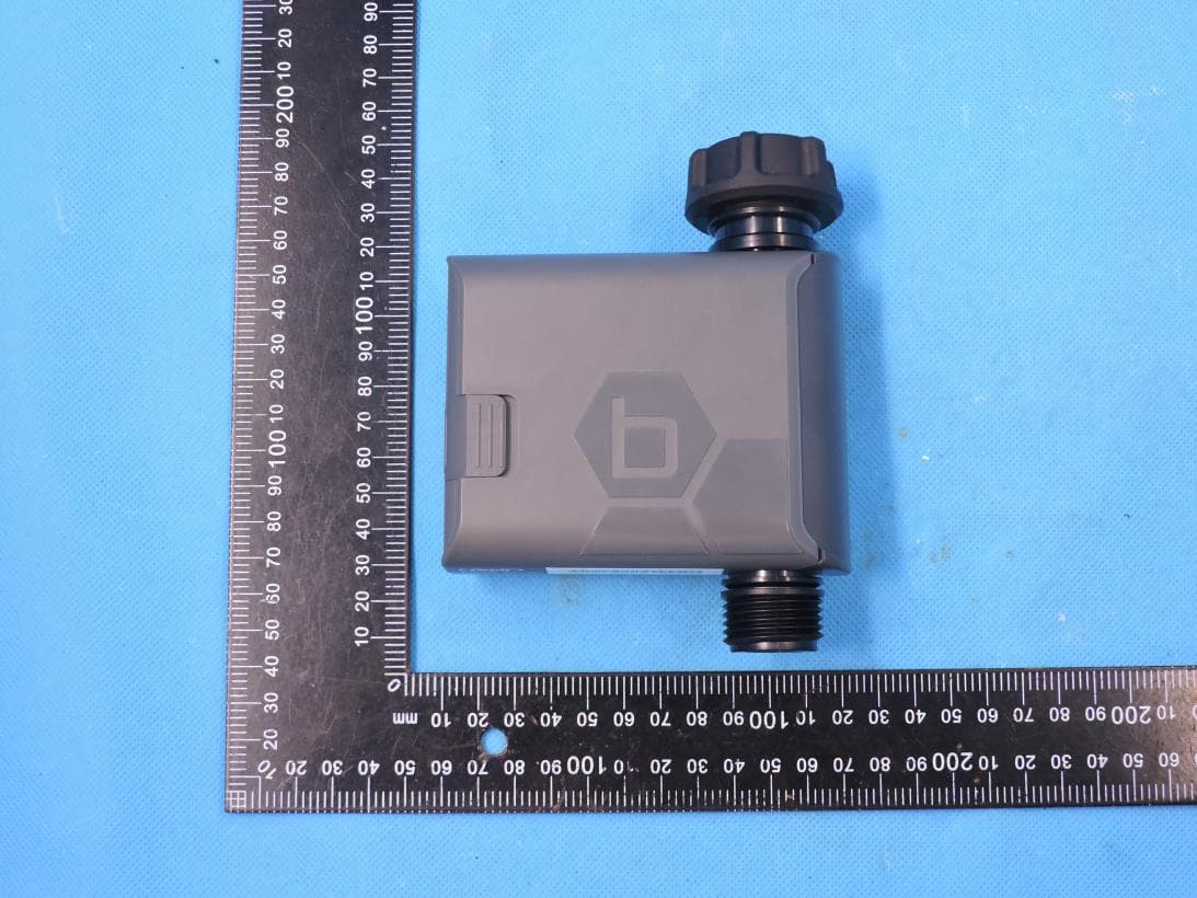
ML6HT25G2
Jul 14, 2022Smart Hose Watering Timer
Equipment Class
DTS - Digital Transmission System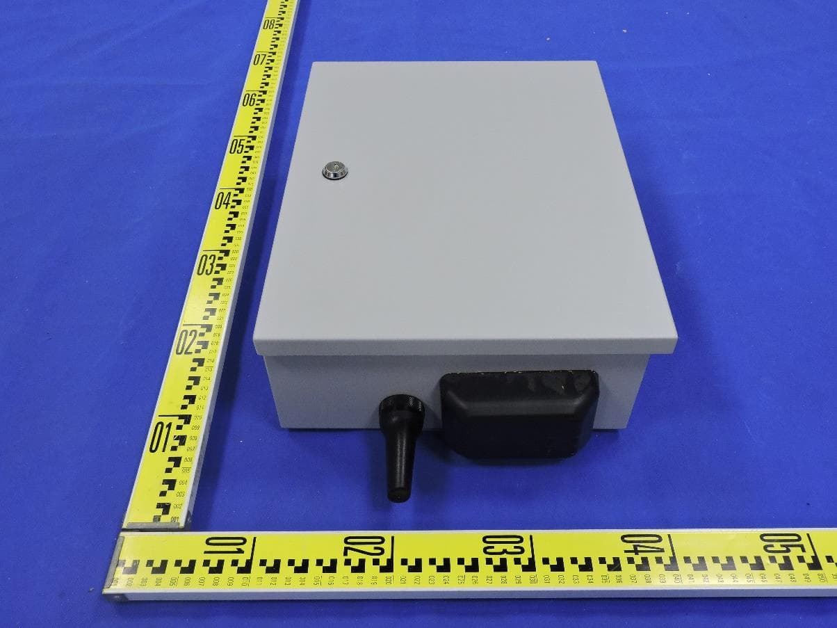
ML6HSC
Jul 10, 2022High Station Count Controller with BLE, 2.4GWIFI, 5GWIFI and LPWAN
Equipment Class
DTS - Digital Transmission System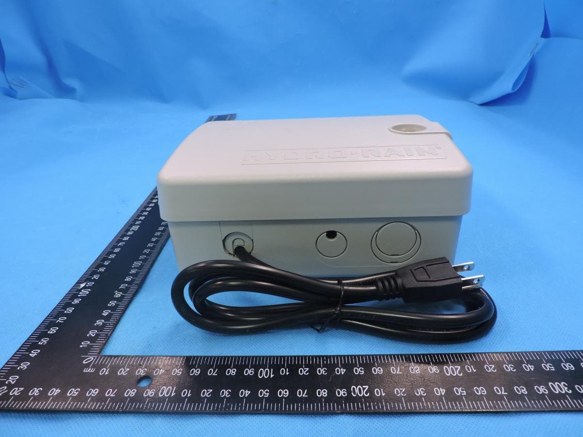
ML6WT25E
Jul 15, 2021B-HYVE Smart WiFi Indoor Sprinkler Timer
Equipment Class
DTS - Digital Transmission System