MLLGLXPT2Wireless Data Collection Transmitter
Miltel Communications Ltd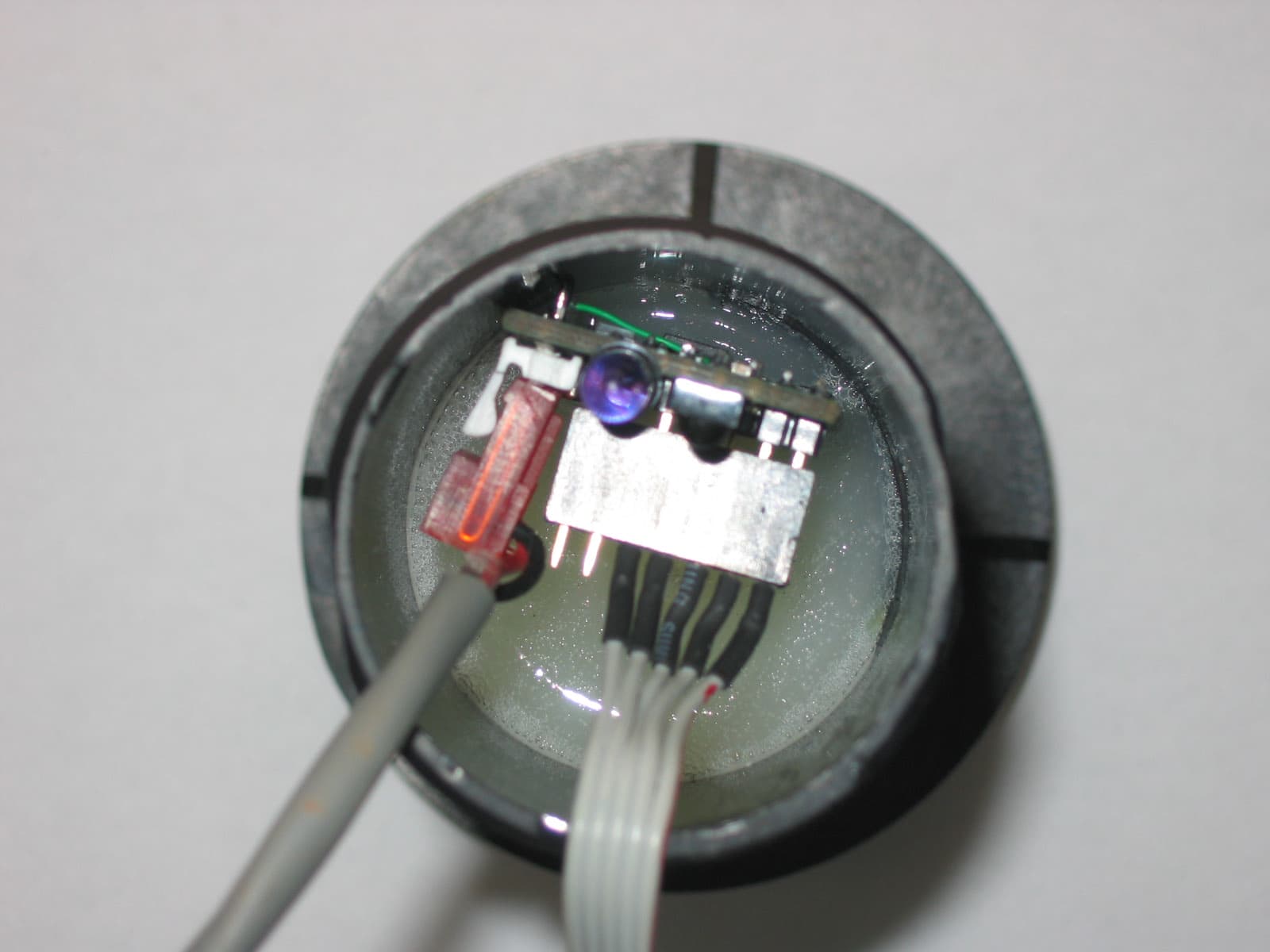
Click to zoom
Application Details
- Equipment Class
- TNB - Licensed Non-Broadcast Station Transmitter
- Date of Grant
- Sep 16, 2005
- Application Purpose
- Original Equipment
- Date of Application
- Sep 16, 2005
- Equipment Note
- Wireless Data Collection Transmitter
- Frequency Range
- 450.00000000 - 470.00000000
- Company
- Miltel Communications Ltd
- Country
- Israel
Documents & Files
Document Text
Text extracted from the exhibit documents filed with the FCC. Open a document above to read the original.
Users Manual
Miltel Transmitter Wireless Transmitter for Data Collection FCC ID: MLLGLXPT2 User Manual Miltel Communications Ltd. August 2005 Page 2 of 14 Miltel Galaxy Pit2 Transmitter Table of Contents Table of Contents.......................................................................................................... 2 Introduction 3 1.1 Purpose and Use............................................................................................ 3 1.2 System General Description ........................................................................... 3 Theory of Operation...................................................................................................... 4 2.1 General Description ........................................................................................ 4 2.2 Block Diagram Description ............................................................................. 6 2.2.1 General........................................................................................................... 6 2.2.2 Description of Operation ................................................................................. 7 Technical Characteristics............................................................................................. 8 3.1 Technical Specification................................................................................... 8 3.1.1 Electrical ......................................................................................................... 8 3.1.2 Physical .......................................................................................................... 8 Installation Instructions................................................................................................ 9 4.1 General........................................................................................................... 9 4.2 Installation ...................................................................................................... 9 Regulatory Compliance............................................................................................... 12 5.1 FCC Statement............................................................................................. 12 Page 3 of 14 Miltel Galaxy Pit2 Transmitter Chapter 1 Introduction 1.1 Purpose and Use The Miltel Galaxy Pit 2 Transmitter (FCC ID: MLLGLXPT2) is a data link transmitter that is used for data acquisition in Miltel’s telemetric data collection system. This device is installed on-site by a professional field technician, thus it includes technical terms. The equipment is not to be installed by a non-professional individual that has not been trained and authorized. 1.2 System General Description The Miltel data collection system is a computerized fully system incorporating one- way transmitters that automatically collect data from utility meters and/or other sensors. The system requires no human intervention after initial installation. The system enables remote, continuous and accurate reading of water or gas consumption. The Miltel Galaxy Pit2 transmits the data acquired from various sensors such as water meters, electric meters, to a receiver connected to a regional data concentrator. The concentrator transfers the data to the central computer for data collection and for further analysis and reporting. Page 4 of 14 Miltel Galaxy Pit2 Transmitter Chapter 2 Theory of Operation 2.1 General Description The Miltel Galaxy Pit 2 Transmitters the first link in the data collection system. It is an independent unit that does not require an external power source, wiring, or the preparation of any special infrastructure. The unit is installed in proximity to the physical sensor and can be connected to several different sensors in parallel (for example four water meters of adjacent apartment, etc). Pictures 2-1 (see next page) show typical installations of a Miltel Galaxy Pit 2 Transmitter unit. The unit can be connected to any type of sensor which has a digital output, analog output, dry contact pulsed output (a passive magnetic open/short reed relay), or any active pulse or encoded output. The Miltel Galaxy Pit 2 Transmitter acquires the data from the sensor and stores this data in its internal memory. The unit includes a miniature RF transmitter which transmits the data on a periodic basis to a regional concentrator. Page 5 of 14 Miltel Galaxy Pit2 Transmitter Figure 2-1: Miltel Transmitter Typical Pit Installation Miltel Pit Transmitter Page 6 of 14 Miltel Galaxy Pit2 Transmitter 2.2 Block Diagram Description 2.2.1 General Figure 2-2 describes the block diagram of the Miltel Galaxy Pit2 Transmitter. This device consists of two major sections, all using a common power source: ¾ Digital section (Micro Controller) ¾ RF section A 3.6 volts Lithium battery provides power to all parts of the device. The power supply for the RF section is controlled via the Tx switch (not shown), thus cutting of power to the transmitter unless necessary for actual data transmission (standby mode). Figure 2-2: Miltel Galaxy Pit 2 Transmitter Block Diagram Sensor 1 Sensor n Sensing and Support Circuitry (Input Port) Micro- Controller RF Transmitter Antenna Battery Device Enclosure Magnetic Switch Page 7 of 14 Miltel Galaxy Pit2 Transmitter 2.2.2 Description of Operation The digital section of the Miltel Galaxy Pit 2 Transmitter performs the following functions: ¾ Samples analog sensors OR communicates with digital sensors ¾ Accumulates data for each sensor separately ¾ Stores data (including alarms) in internal memory ¾ Interfaces the data to the RF section The controller gathers the data for 10-240 minutes before initiating a transmission. If any of the counters/sensors has exceeded a preset value, or any alarm (such as tamper) has been received, the controller generates a single message immediately. Any further message will include alarm information along with counter data, if alarm condition still exists. Note: The duration interval betwe…
Text truncated - open the document above for the full version.
Cover Letter(s)
Miltel Communications Ltd. 7 Gush Etzion, 4 th Floor Givat-Shmuel, Israel 54030 Tel: +972-3-737-1333 Fax:+972-3-737-1331 August 14, 2005 Federal Communications Commission Authorization and Evaluation Division Re: Miltel Communications, FCC ID: MLLGLXPT2 Confidentiality Request Pursuant to sections 0.457 and 0.459 of the Commission’s rules, the Applicant hereby requests confidential treatment of information accompanying this Application as outlined below: • Schematics (electronic diagrams) • Block Diagrams • Operational Descriptions (incl. tune-up information) • Parts List • Internal Photos The above materials contain trade secrets and proprietary information not customarily released to the public. The public disclosure of these matters might be harmful to the Applicant and provide unjustified benefits to its competitors. The product is supplied to the customer in an epoxy potted tube that does not expose any of the internal components. The tube enclosure is manufactured and supplied as a non-intrusive device and can not be serviced or dismantled. The design of the antenna and the unique solution of fitting the transmitter and the antenna in such a small enclosure are in the process of patent application. The installer and the customer can not reveal any of the internal parts, therefore we request to keep the internal pictures confidential. The Applicant understands that pursuant to Rule 0.457, disclosure of the Application and all accompanying documentation will not be made before the date of the Grant for this Application. Sincerely, Yarum Locker Co- C.E.O.
Cover Letter(s)
American Telecommunications Certification Body Inc. 6731 Whittier Ave, McLean, VA 22101 September 8, 2005 RE: Miltel Communications Ltd. FCC ID: MLLGLXPT2 After a review of the submitted information, I have a few comments on the above referenced Application. 1) The operational description mentions other components of the system. The concentrator appears to only be verified according to information in the operational description. Does this device contain a transmitter? Does it contain a RX. Note that if it contains a RX it would be subject to Certification or DoC as desired by the manufacturer. Please explain. 2) Please explain the limit of 118.2 on page 9 of the report. 3) Please verify your power results. From your tables I believe you corrected for the dBi of the antenna which would give the results in EIRP, not ERP. If I interpret you results correction, I believe the results would be 14.52 dBm ERP or 16.67 dBm EIRP. However is the correction in the table actually for dBi and not dBd. Please review. Note this may affect information given in the theory of operation, chapter 3 of the users manual, and elsewhere in the test report (page 6, etc.). Please review. Compare sections 7.3.4.5 and 7.1.3.4. Notice the difference between dBi and dBd. 4) Please explain the limit of -17.83 dBm on page 22. It was thought the limit is -20 dBm....Note that technically -20 dBm does not apply to 90.217. If the limit is based upon the 30 dB requirement of 90.217, then shouldn’t this limit vary for low, middle, and high channels. Please explain. 5) Please explain why the wide-span plots on page 33 appear to show much higher results that the independent measurement of each harmonic shown later on the following pages. 6) FYI....The table in 7.4.2 appears to assume a center frequency of 450 MHz, while the actual frequency appears to be 450.00625 MHz. A similar problem appears for the high frequency reported (470 assumed vs. 469.99375 MHz). Compliance can still be seen from the table provided however it would be best to report proper results. 7) Please provide calculations to support emissions designator. Timothy R. Johnson Examining Engineer mailto: [email protected] The items indicated above must be submitted before processing can continue on the above referenced application. Failure to provide the requested information may result in application termination. Correspondence should be considered part of the permanent submission and may be viewed from the Internet after a Grant of Equipment Authorization is issued. Please do not respond to this correspondence using the email reply button. In order for your response to be processed expeditiously, you must submit your documents through the AmericanTCB.com website. Also, please note that partial responses increase processing time and should not be submitted. Any questions about the content of this correspondence should be directed to the sender.
Cover Letter(s)
HERM O N LA BO RA TO RIES September 15, 2005 American TCB 6731 Whittier Ave Suite C110 McLean, VA 22101 Attn: Mr. T. Johnson, Examining Engineer RE: your e-mail dated September 8, 2005; Miltel Communications Ltd. FCC ID:MLLGLXPT2, ATCB002735 Dear Mr. Johnson, Please find below the answers to your questions. 1) The concentrator is connected to a Receiver device that has been certified. The device connected to the concentrator is Miltel’s Receiver/Repeater model 2A (FCC ID: MLLGL2RPT450). This device is sold with the concentrator. The user can not connect any other reception device. 2) The ERP limit is 120 mW. Equivalent field strength limit at 3 meter can be found using following equation: E limit[dBμV/m] = 20 x log 10 {√ 30 x EIRP [W] /r} + 120 = 20 x log 10 {√ 30 x ERP [W] x 1.64/r} + 120 [] mVdBE mVdB /2.118120 3 64.112.030 log20 10]/[limit μ μ =+ ×× ×= The revised Operational_description_16356_rev1, User_Manual_16356_rev1 and test report MILRAD_FCC.16356_rev1 with corrected pages 6, 7 was uploaded on September 15, 2005. 3) The test report page 9, Table 7.1.3 was revised for correct ERP value, refer to MILRAD_FCC.16356_rev1. Please state EIRP power in the grant if possible according to request of the manufacturer (MIltel) for marketing purposes. 4) The test report pages 18, 21, 22 were corrected. 5) Please refer to the explanation with illustration in the attachment below. 6) The Table 7.4.2 was corrected. 7) The device uses FSK modulation with the maximum frequency deviation +/- 3 kHz and the highest modulating frequency +/- 2.4 kHz. Upon this the necessary emission bandwidth is 2*(3.0+2.4)=10.8 kHz, and the correct emission designator is 10K8F1D. The revised ATCB Form 731 and Operational_description_16356_rev1 were uploaded on September 15, 2005. Thank you. Sincerely, Marina Cherniavsky, certification engineer Hermon Laboratories HERM O N LA BO RA TO RIES Attachment to item 5 Low frequency Independent measurements results: 1.35 GHz – 71.98 dBuV/m 1.80 GHz – 70.94 dBuV/m 2.25 GHz – 60.24 dBuV/m 2.70 GHz – 73.42 dBuV/m Mid frequency Independent measurements results: 1.38 GHz – 71.45 dBuV/m 1.84 GHz – 65.59 dBuV/m 2.30 GHz – 61.20 dBuV/m 2.76 GHz – 76.38 dBuV/m HERM O N LA BO RA TO RIES High frequency Independent measurements results: 1.41 GHz – 61.79 dBuV/m 1.88 GHz – 58.26 dBuV/m 2.35 GHz – 61.00 dBuV/m 2.82 GHz – 56.35 dBuV/m
Cover Letter(s)
American Telecommunications Certification Body Inc. 6731 Whittier Ave, McLean, VA 22101 September 16, 2005 RE: Miltel Communications Ltd. FCC ID: MLLGLXPT2 After a review of the submitted information, I have a few comments on the above referenced Application. 1) FYI....The bandedge limits of table 7.4.2 still are based upon incorrect assumed center frequencies. However compliance can still be determined after careful review. Timothy R. Johnson Examining Engineer mailto: [email protected] The items indicated above must be submitted before processing can continue on the above referenced application. Failure to provide the requested information may result in application termination. Correspondence should be considered part of the permanent submission and may be viewed from the Internet after a Grant of Equipment Authorization is issued. Please do not respond to this correspondence using the email reply button. In order for your response to be processed expeditiously, you must submit your documents through the AmericanTCB.com website. Also, please note that partial responses increase processing time and should not be submitted. Any questions about the content of this correspondence should be directed to the sender.
External Photos
Miltel Communications Ltd. FCC ID:MLLGLXPT2 Date: August 2005 Page 1 of 5 EXTERNAL PHOTOGRAPHS This document contains 4 photographs Miltel Communications Ltd. FCC ID:MLLGLXPT2 Date: August 2005 Page 2 of 5 Photograph No.1 Galaxy Pit2 transmitter General view Miltel Communications Ltd. FCC ID:MLLGLXPT2 Date: August 2005 Page 3 of 5 Photograph No.2 Galaxy Pit2 transmitter Bottom view Miltel Communications Ltd. FCC ID:MLLGLXPT2 Date: August 2005 Page 4 of 5 Photograph No.3 Galaxy Pit2 transmitter Bottom view without wires Miltel Communications Ltd. FCC ID:MLLGLXPT2 Date: August 2005 Page 5 of 5 Photograph No.4 Galaxy Pit2 transmitter General view without plastic rings and wires
ID Label/Location Info
Miltel Communications Ltd. Galaxy Pit2 Transmitter ID Label 1 ID Label –FCC ID:MLLGLXPT2 The Pit2 transmitter is installed in a tube enclosure. The tube face includes the FCC ID which will be molded as shown below. Due to the limited dimensions of the product's enclosure, the product will not have any additional label. FCC ID: MLLGLXPT2 FCC ID: MLLGLXPT2
Test Report
Hermon Laboratories Ltd. P.O.Box 23, Binyamina 30500, Israel Tel. +972 4628 8001 Fax. +972 4628 8277 E-mail: [email protected] Page 1 of 92 Report ID: MILRAD_FCC.16356_rev1.doc Date of Issue: 8/16/2005 Electrical TEST REPORT ACCORDING TO: FCC CFR 47 PART 90 §90.217(b) AND PART 15 SUBPART B FOR: Miltel Communications Ltd. Wireless transmitter for data collection Model:Galaxy Pit2 FCC ID:MLLGLXPT2 This report is in conformity with ISO/ IEC 17025. The A2LA logo endorsement applies only to the test methods and the standards that are listed in the scope of Hermon Laboratories accreditation. The test results relate only to the items tested. This test report shall not be reproduced in any form except in full with the written approval of Hermon Laboratories Ltd. Report ID: MILRAD_FCC.16356_rev1.doc Date of Issue: 8/16/2005 Page 2 of 92 Table of contents 1 Applicant information..................................................................................................................................................... 3 2 Equipment under test attributes .................................................................................................................................... 3 3 Manufacturer information .............................................................................................................................................. 3 4 Test details.................................................................................................................................................................... 3 5 Tests summary.............................................................................................................................................................. 4 6 EUT description............................................................................................................................................................. 5 6.1 General information....................................................................................................................................................... 5 6.2 Ports and lines .............................................................................................................................................................. 5 6.3 Support and test equipment .......................................................................................................................................... 5 6.4 Operating frequencies ................................................................................................................................................... 5 6.5 Changes made in the EUT ............................................................................................................................................ 5 6.6 Test configuration.......................................................................................................................................................... 5 6.7 Transmitter characteristics ............................................................................................................................................ 6 7 Transmitter tests according to 47CFR part 90 requirements......................................................................................... 7 7.1 Effective radiated power of carrier................................................................................................................................. 7 7.2 Occupied bandwidth test ............................................................................................................................................. 13 7.3 Radiated spurious emission measurements................................................................................................................ 18 7.4 Band edge emission.................................................................................................................................................... 57 7.5 Frequency stability test................................................................................................................................................ 65 7.6 Transient frequency behaviour test ............................................................................................................................. 67 7.7 Radiated emission measurements .............................................................................................................................. 72 8 APPENDIX A Test equipment and ancillaries used for tests....................................................................................... 75 9 APPENDIX B Measurement uncertainties................................................................................................................... 77 10 APPENDIX C Test facility description ......................................................................................................................... 78 11 APPENDIX D Specification references ....................................................................................................................... 78 12 APPENDIX E Abbreviations and acronyms................................................................................................................. 79 13 APPENDIX F Test equipment correction factors ......................................................................................................... 80 Report ID: MILRAD_FCC.16356_rev1.doc Date of Issue: 8/16/2005 Page 3 of 92 1 Applicant information Client name: Miltel Communications Ltd Address: 7 Gush-Etzion, 4 th floor, Givat-Shmuel 54030, Israel Telephone: +972 3737 1333 Fax: +972 3737 1331 E-mail: [email protected] Contact name: Mr. Erez Sharabi 2 Equipment under test attributes Product name: Wireless transmitter for data collection Model(s): Galaxy Pit2 Software release: 1.09 Receipt date 6/29/2005 3 Manufacturer information Manufacturer name: Miltel Communications Ltd Address: 7 Gush-Etzion, 4 th floor, Giva…
Text truncated - open the document above for the full version.
Test Setup Photos
Miltel Communications Ltd. FCC ID:MLLGLXPT2 Date: August 2005 Page 1 of 9 SETUP PHOTOGRAPHS This document contains 8 photographs Miltel Communications Ltd. FCC ID:MLLGLXPT2 Date: August 2005 Page 2 of 9 Photograph No.1 Effective radiated power, occupied bandwidth, radiated emissions measurement setup at OATS Miltel Communications Ltd. FCC ID:MLLGLXPT2 Date: August 2005 Page 3 of 9 Photograph No.2 Radiated emissions measurement setup at OATS close view Miltel Communications Ltd. FCC ID:MLLGLXPT2 Date: August 2005 Page 4 of 9 Photograph No.3 Setup for substitution ERP measurements Miltel Communications Ltd. FCC ID:MLLGLXPT2 Date: August 2005 Page 5 of 9 Photograph No.4 Setup for substitution measurements of spurious emissions Miltel Communications Ltd. FCC ID:MLLGLXPT2 Date: August 2005 Page 6 of 9 Photograph No.5 Frequency stability measurement setup Miltel Communications Ltd. FCC ID:MLLGLXPT2 Date: August 2005 Page 7 of 9 Photograph No.6 Transient frequency test setup Miltel Communications Ltd. FCC ID:MLLGLXPT2 Date: August 2005 Page 8 of 9 Photograph No.7 Radiated emissions measurement setup in the anechoic chamber with biconilog antenna Miltel Communications Ltd. FCC ID:MLLGLXPT2 Date: August 2005 Page 9 of 9 Photograph No.8 Band edge emissions measurement setup in the anechoic chamber with biconilog antenna
Contact Information
Applicant
Yarum Locker(General Manager)
Technical Contact
Hermon LaboratoriesAlex Usoskin
[email protected]972 4 628-8001
Harakevet Industrial zone · Binyamina · Israel
Non-Technical Contact
Miltel CommunicationsYarum Locker
[email protected]972 3737 13333
Test Firm
Hermon Laboratories Ltd.Alexander Usoskin
Technical Specifications
| # | Rule Parts | Frequency Range | Power Output | Emission | Tolerance |
|---|---|---|---|---|---|
| 1 | 90.217(b) | 450 MHz - 470 MHz | 46.50 mW | 10K8F1D | 900.0000000000 Hz |
Other Applications from Miltel Communications Ltd
MLLGL3RPT450
Oct 28, 2010TRANSCEIVER 3A
Equipment Class
TNB - Licensed Non-Broadcast Station Transmitter
MLLGL2RPT150
Jan 14, 2006Repeater
Equipment Class
TNB - Licensed Non-Broadcast Station Transmitter
MLLGL2RPT450
Jan 23, 2005Repeater
Equipment Class
TNB - Licensed Non-Broadcast Station Transmitter
MLLIWCTX15-17
Dec 21, 2004Field Station
Equipment Class
TNB - Licensed Non-Broadcast Station Transmitter
MLLIWCRPT15-17
Dec 21, 2004IrriWise Repeater
Equipment Class
TNB - Licensed Non-Broadcast Station Transmitter