MLLIWCRPT15-17IrriWise Repeater
Miltel Communications Ltd
Click to zoom
Application Details
- Equipment Class
- TNB - Licensed Non-Broadcast Station Transmitter
- Date of Grant
- Dec 21, 2004
- Application Purpose
- Original Equipment
- Date of Application
- Dec 21, 2004
- Equipment Note
- IrriWise Repeater
- Frequency Range
- 150.00000000 - 170.00000000
- Company
- Miltel Communications Ltd
- Country
- Israel
Documents & Files
Document Text
Text extracted from the exhibit documents filed with the FCC. Open a document above to read the original.
Users Manual
IrriWise ™ Wireless Crop Monitoring System IrriWise Transmitter IrriWise Transceiver (Receiver/Repeater) User Manual Miltel Communications Ltd. September 2004 1-2 CHAPTER 1 INTRODUCTION 1.1 GENERAL This chapter provides a functional description of the IrriWise TM – Wireless Crop Monitoring System. This system has been designed to provide the grower with real-time data collected from the field, thereby providing better control over irrigation scheduling and farm resources. 1.1.1 What Is The System Intended For? The IrriWise TM system is a management tool intended to provide the grower with better control over crop irrigation and farm resources by means of data collection and its interpretation. Data is collected from the field using state of the art radio technology and transferred to your PC, where it is presented in user-friendly software, enabling easy data interpretation, improving real-time decisions and analysis of history. Data is sampled from the sensors and transmitted to base station as follows: • Soil moisture sensors are measured every 15 minutes and transmitted every 30 minutes. • Weather station sensors are measured every 5 minutes and an average reading is transmitted every 15 minutes. • Water meter readings are sent at the beginning and end of irrigations and every 10 minutes during irrigation. 1-3 1.1.2 Wireless Crop Monitoring System Diagram A basic diagram of the Wireless Crop Monitoring System is displayed in Figure 1-1. Since the system is modular, different configurations and components are possible. Ra n g e : Up to 4 km (2.5 miles) Ra n g e : Up to 10 km (7 miles) Ba se St a t i o n Fi e l d St a t i o n Re m o t e Ac c e ss (Modem) Re m o t e Access (LAN) Re p e a t e r Receiver Figure 1-1. Wireless Crop Monitoring System Diagram 1-4 1.1.3 System Components The Wireless Crop Monitoring System is comprised of the following components: a. Wireless system: • Base station – PC, IrriWise Receiver (transceiver) and antenna • IrriWise Transmitters • IrriWise Repeater (transceiver) b. Radio Manager TM application – radio and network management software. c. IrriWise TM application – user-friendly graphing and data analysis software. d. IrriDial TM application – remote access dialer enabling data download from various IrriWise TM users. e. Sensors: • Gro-Point TM – a volumetric soil moisture sensor based on TDT technology with fast and accurate response to changes in soil moisture. • Tensiometer transducer – a special transducer that enables accurate and reliable measurement of most traditional tensiometers. • Weather station (up to 8 different sensors) – a fully modular weather station for measuring the local microclimate. Supports the following sensors: air temperature, relative humidity, solar radiation, wind speed, wind direction, rain gauge, leaf wetness and soil temperature. Transmits calculated data such as ET, dew point and gust. The rain gauge can be installed as a standalone unit independent of the weather station. • Water meter – various types of water meters: • Lateral or mainline flow meter – standard pulse-type flow meters. • 1/2” drip-line flow meter to record single drip-line irrigation volume and runtime. • Fertilizer flow meter can be connected to the system to record when and how much fertilizer has been applied. 1-5 • Tipping bucket flow sensor to record irrigation volume and runtime based on individual dripper. 1.1.3.1 Wireless System The wireless system provides the remote access interface. The transmission range of the wireless system is up to 4 km (2.5 miles), depending on the following factors: a. Interference (noise) on the selected frequency. The “cleaner” the frequency, the longer the range. b. Crop clearance – radio waves do not penetrate foliage very well, especially when wet from rain or dew. c. Topographical conditions – the extent of line of sight (LOS) pureness and positioning height affect the transmission range accordingly. Base Station Receiver and Antenna The base station includes the antenna and receiver as a joint unit and is responsible for the reception of data sent by the transmitters and for its transfer to the PC via RS232 (see Figure 1-2). 1-6 Antenna Re c e i v e r RS2 3 2 a n d Po w e r Su p p l y Output to PC Input From Ante nna Rear Connection to Pole Figure 1-2. Antenna and Receiver 1-7 PC A PC computer is required for the collection of the received data. This PC contains the Radio Manager TM and IrriWise TM software. Remote users can access the data stored on this PC by means of modem and/or LAN and IrriDial TM application. The technical specification of PC requirements is as follows: a. PC operating system – Windows 2000 or Windows XP. b. CPU – minimum Pentium III 900 MHz. c. RAM – minimum 128 MB. d. Available disk space – minimum 5 GB. e. Unused serial port (cannot be shared with Palm Pilot or other applications). f. Ability to remain switched ON 100% of the time. g. Quality surge suppressor power strip. h. Quality UPS plugged to surge suppressor. Transmitter The transmitter (Figure 1-3) enables to send data by means of RF transmission. This device is equipped with a battery designed to provide an operation term of at least 6 years (except for weather station transmitter battery, which lasts for 3 years) and is highly reliable. The transmitter enables the transmission to a range of up to 4 km (2.5 miles). There are four types of transmitters, as displayed in Figure 1-3. 1-8 Weather Station Transm itter Gro Point Tra nsm itte r TM Water Meter Transm itter Tensiometer Tra nsm itter Figure 1-3. Transmitter Types 1-9 Repeater The repeater is externally similar to the receiver previously described in this section (except for the cable for connection to the PC). This device enables to extend transmission range by to 10 km (6.2 miles) depending on topographical conditions. The repeater should be located at a strategic point between the transmitters and base station. It picks up the transmitted signal and repeats it. This unit r…
Text truncated - open the document above for the full version.
Cover Letter(s)
American Telecommunications Certification Body Inc. 6731 Whittier Ave, McLean, VA 22101 November 24, 2004 RE: Miltel Communications Ltd. FCC ID: MLLIWCRPT15-17 After a review of the submitted information, I have a few comments on the above referenced Application. 1) The internal photographs may not normally be held confidential strictly on the basis of trade secrets. Please remove this justification from the letter of confidentiality or provide a better justification. As an alternative, you may use a black marker to "black out" the top of any readable components and provide new internal photographs. Please let us know how you wish to proceed with this issue. 2) It is not clear how this behaves as a repeater. Is the information down converted? Does the TX rebroadcast any information it the 150-170 MHz band, or does it only re-broadcast information it is capable of de-modulating? Please provide further information for this mode of operation and clarify if this device is a booster or repeater. These are defined as follow: Booster is a device that automatically reradiates signals from base transmitters without channel translation, for the purpose of improving the reliability of existing service by increasing the signal strength in dead spots. An “in-building radiation system” is a signal booster. These devices are not intended to extend the size of coverage from the originating base station. A booster can be either single or multiple channels. Repeater is a device that retransmits the signals of other stations. Repeaters are different from boosters in that they can include frequency translation and can extend coverage beyond the design of the original base station. A repeater is typically single channel but can also be multiple channels. 3) If this is device considered a single channel (Class A) or multi channel (Class B) repeater/booster? Signal booster. A device at a fixed location which automatically receives, amplifies, and retransmits on a one-way or two-way basis, the signals received from base, fixed, mobile, and portable stations, with no change in frequency or authorized bandwidth. A signal booster may be either narrowband (Class A), in which case the booster amplifies only those discrete frequencies intended to be retransmitted, or broadband (Class B), in which case all signals within the passband of the signal booster filter are amplified. Depending on its classification, was the appropriate testing performed for intermodulation? 4) Please see attached guidelines for amps, repeaters, boosters. Please make sure all appropriate guidelines are followed. 5) In repeater mode of operation, please explain how the device performs power leveling. How does the output signal vary as a function of input signal level? 6) For purposes of testing, how does the device generate an output signal. If a input signal was required, how was a input level determined. Please provide further information (i.e. explain the alternative signal used). --- Continue on Next Page --- z Page 2 November 30, 2004 7) Normally for testing the emissions bandwidth of amplifiers, boosters, repeaters, the input signal is compared to the output signal. This does not appear to have been performed this way. Please explain. 8) Please provide information regarding the antennas used with the system. 9) Please provide RF exposure information for this device. 10) Please consider adding information to the users manual regarding licensing requirements. Examples of this are: The equipment user is required by the radio service rules to obtain a license before operating the equipment. Licensing of this equipment is the user’s responsibility, and licensability depends on the user’s classification and application, and on the selected frequency. The user is strongly urged to contact the appropriate telecommunications authority concerning proper licensing, and before choosing and ordering frequencies. 11) Please explain the reference level settings for plots 7.3.1 – 7.3.3 and 7.5.1 – 7.5.6. Is this the unmodulated output power. Normally a second unmodulated plot is also shown on the same plot to show the to equal the reference line level. If so, please explain why the reference levels between the 2 sets of plots do not match. 12) Please explain why the carrier is so low in plots 7.4.7 – 7.4.9. Was the antenna terminated for this test? 13) It is uncertain why the emission designator for this device is only 5K85F1D. It is assumed that it will rebroadcast emission received from FCC ID MLLIWCTX15-17 which has emission designator 12K5F1D. Timothy R. Johnson Examining Engineer mailto: [email protected] The items indicated above must be submitted before processing can continue on the above referenced application. Failure to provide the requested information may result in application termination. Correspondence should be considered part of the permanent submission and may be viewed from the Internet after a Grant of Equipment Authorization is issued. Please do not respond to this correspondence using the email reply button. In order for your response to be processed expeditiously, you must submit your documents through the AmericanTCB.com website. Also, please note that partial responses increase processing time and should not be submitted. Any questions about the content of this correspondence should be directed to the sender.
Cover Letter(s)
Hello Tim, Please find below our replies to your comments. 1) Please find attached the new set of internal photographs. 2) The transceiver completely demodulates the received messages as explained in the attached Repeater Operation description and shown in the attached block diagram. Upon this there is no change in the transmitted RF signal associated with transceiver mode of operation. 3) The same as 2). 4) The same as 2). 5) The same as 2). 6) The same as 2). 7) The same as 2). 8) Please refer to the attached document . 9) RF exposure was not evaluated as the RF output power does not exceed 1.5W as provided in section 2.1091(c) of the FCC rules. 10) Please refer to the last page of the attached user manual. 11) The reference level shown in plots 7.3.1-7.3.3 and 7.5.1-7.5.6 was adjusted to the total power of the transmitter in both cases. The difference in the reference level settings was caused by slightly different set ups (external attenuator, RF cable, spectrum analyzer) and as both of the measurements are relative no corrections were applied. 12) Radiated spurious emissions were tested with RF antenna connector terminated with 50 Ohm dummy load. 13) The device use FSK modulation with the maximum frequency deviation +/- 3 kHz and the highest modulating frequency +/- 2.4 kHz. Upon this the necessary emission bandwidth is 2*(3.0+2.4)=10.8 kHz and the correct emission designator is 10K8F1D. Best regards. Michael Nikishin. Page 1 of 1Milltel MLLIWCRPT15-17 12/20/2004Printed for "Timothy R. Johnson" <[email protected]>
Cover Letter(s)
Miltel Communications Ltd. 7 Leshem Street, 4 th Floor P.O. Box 7374 Petach Tikva, Israel 49170 Tel: 972-3-926-9550 Fax: 972-3-924-6550 21 December 2004 Subject: Request for Confidentiality FCC ID: IWCRPT15-17 Dear Gentlemen, Pursuant to sections 0.457 and 0.459 of the Commission’s rules we herby apply to you with request to withhold the following confidential information in the Application for Certification for FCC ID: MLLIWCRPT15-17. The confidential information accompanying this Application is outlined below: • Schematics (electronic diagrams) • Block Diagram(s) • Operational Technical Description (incl. tune-up information etc.) • Parts List The above materials contain trade secrets and proprietary information not customarily released to the public. The public disclosure of these matters might be harmful to the Applicant and provide unjustified benefits to its competitors. The Applicant understands that pursuant to Rule 0.457, disclosure of the Application and all accompanying documentation will not be made confidential before the date of the Grant for this Application. Sincerely, Yarum Locker – Co-C.E.O.
External Photos
FCC ID:MLLIWCRPT15-17 Date: October 2004 Page 1 of 9 EXTERNAL PHOTOGRAPHS This document contains 8 photographs FCC ID:MLLIWCRPT15-17 Date: October 2004 Page 2 of 9 Photograph No.1 Irriwise transceiver General view FCC ID:MLLIWCRPT15-17 Date: October 2004 Page 3 of 9 Photograph No.2 Irriwise transceiver General view FCC ID:MLLIWCRPT15-17 Date: October 2004 Page 4 of 9 Photograph No.3 Irriwise transceiver Front view FCC ID:MLLIWCRPT15-17 Date: October 2004 Page 5 of 9 Photograph No.4 Irriwise transceiver Antenna connection view FCC ID:MLLIWCRPT15-17 Date: October 2004 Page 6 of 9 Photograph No.5 Irriwise transceiver Side panel view FCC ID:MLLIWCRPT15-17 Date: October 2004 Page 7 of 9 Photograph No.6 Irriwise transceiver antenna connectors FCC ID:MLLIWCRPT15-17 Date: October 2004 Page 8 of 9 Photograph No.7 Irriwise transceiver antenna connectors FCC ID:MLLIWCRPT15-17 Date: October 2004 Page 9 of 9 Photograph No.8 Irriwise transceiver Rear side veiw
ID Label/Location Info
FCC ID Label 1. The following document provides the information regarding the FCC ID label . 2. The equipment label shown below is affixed to the Irriwise Transceiver on the back panel Label Dimensions: 58 mm. x 24 mm. Label Location: Transceiver back panel FCC ID: MLLIWCRPT15-17 Model: Irriwise Transceiver S/N: ___________ Miltel Communications Made in Israel This device complies with Part 15 of the FCC Rules. Operation is subject to the following two conditions: (1) this device may not cause harmful interference, and (2) this device must accept any interference received, including interference that may cause undesired operation. Label location, FCC ID:MLLIWCRPT15-17 On Irriwise Transceiver rear panel Label FCC ID:MLLIWCRPT15-17
Internal Photos
FCC ID:MLLIWCRPT15-17 Date: October 2004 Page 1 of 7 INTERNAL PHOTOGRAPHS This document contains 6 photographs FCC ID:MLLIWCRPT15-17 Date: October 2004 Page 2 of 7 Photograph No.1 Irriwise transceiver Internal view FCC ID:MLLIWCRPT15-17 Date: October 2004 Page 3 of 7 Photograph No.2 Irriwise transceiver Internal view FCC ID:MLLIWCRPT15-17 Date: October 2004 Page 4 of 7 Photograph No.3 Irriwise transceiver PCB top view FCC ID:MLLIWCRPT15-17 Date: October 2004 Page 5 of 7 Photograph No.4 Irriwise transceiver PCB second side view FCC ID:MLLIWCRPT15-17 Date: October 2004 Page 6 of 7 Photograph No.5 Irriwise transceiver PCB second side, close view FCC ID:MLLIWCRPT15-17 Date: October 2004 Page 7 of 7 Photograph No.6 Irriwise transceiver PCB second side, close view
Test Report
Hermon Laboratories Ltd. P.O.Box 23, Binyamina 30500, Israel Tel. +972 4628 8001 Fax. +972 4628 8277 E-mail: [email protected] Page 1 of 109 Report ID: MILRAD_FCC.15979.doc Date of Issue: 8/31/2004 Electrical TEST REPORT ACCORDING TO: FCC CFR 47 PART 90 §90.217 and PART 15 SUBPART B FOR: Miltel Communications Ltd. Transceiver Models: Irriwise-repeater 153, Irriwise-receiver 153 This report is in conformity with ISO/ IEC 17025. The A2LA logo endorsement applies only to the test methods and the standards that are listed in the scope of Hermon Laboratories accreditation. The test results relate only to the items tested. This test report shall not be reproduced in any form except in full with the written approval of Hermon Laboratories Ltd. Report ID: MILRAD_FCC.15979.doc Date of Issue: 8/31/2004 Project: 15979, Miltel Communications Ltd Page 2 of 109 Table of contents 1 Applicant information..................................................................................................................................................... 3 2 Equipment under test attributes .................................................................................................................................... 3 3 Manufacturer information .............................................................................................................................................. 3 4 Test details.................................................................................................................................................................... 3 5 Tests summary.............................................................................................................................................................. 4 6 EUT description............................................................................................................................................................. 5 6.1 General information....................................................................................................................................................... 5 7 Transmitter tests according to 47CFR part 90 requirements......................................................................................... 6 7.1 Peak output power test.................................................................................................................................................. 6 7.2 Occupied bandwidth test ............................................................................................................................................. 11 7.3 Emission mask test ..................................................................................................................................................... 14 7.4 Radiated spurious emission measurements................................................................................................................ 18 7.5 Band edge emission.................................................................................................................................................... 58 7.6 Spurious emissions at RF antenna connector test ...................................................................................................... 63 7.7 Frequency stability test................................................................................................................................................ 74 7.8 Transient frequency behaviour test ............................................................................................................................. 76 8 Emissions tests according to 47CFR part 15 subpart B requirements ........................................................................ 81 8.1 Conducted emissions .................................................................................................................................................. 81 8.2 Radiated emission measurements .............................................................................................................................. 85 9 APPENDIX A Test equipment and ancillaries used for tests....................................................................................... 94 10 APPENDIX B Measurement uncertainties................................................................................................................... 96 11 APPENDIX C Test facility description ......................................................................................................................... 97 12 APPENDIX D Specification references ....................................................................................................................... 97 13 APPENDIX E Abbreviations and acronyms................................................................................................................. 98 14 APPENDIX F Test equipment correction factors ......................................................................................................... 99 Report ID: MILRAD_FCC.15979.doc Date of Issue: 8/31/2004 Project: 15979, Miltel Communications Ltd Page 3 of 109 1 Applicant information Client name: Miltel Communications Ltd Address: 7 Leshem street, P.O.Box 7374, Petach Tikva, 49170, Israel Telephone: +972 3926 9550 Fax: +972 3924 6550 E-mail: [email protected] Contact name: Mr. Erez Sharabi 2 Equipment under test attributes Product name: Transceiver Model(s): 1) Irriwise-repeater 153, P/N 74300-001050 2) Irriwise-receiver 153, P/N 74300-001210 Receipt date 7/11/2004 3 Manufacturer information Manufacturer name: Miltel Communications Ltd Address: 7 Leshem street, P.O.Box 7374, Petach Tikva, 49170, Israel Telephone: +972 3926 9550 Fax: +972 3924 6550 E-Mail: [email protected] Contact name: Mr. Erez Sharabi 4 Test details Project ID: 15979 Location: Hermon Laboratories Ltd. P.O.Box 23, Binyamina 30500, Israel Test started: 7/11/2004 Test completed: 8/31/2004 Test specification(s): 47…
Text truncated - open the document above for the full version.
Test Setup Photos
FCC ID:MLLIWCRPT15-17 Date: October 2004 Page 1 of 14 SETUP PHOTOGRAPHS This document contains 13 photographs FCC ID:MLLIWCRPT15-17 Date: October 2004 Page 2 of 14 Photograph No.1 Peak output power, occupied bandwidth, conducted emissions measurement setup FCC ID:MLLIWCRPT15-17 Date: October 2004 Page 3 of 14 Photograph No.2 Emission mask measurement setup FCC ID:MLLIWCRPT15-17 Date: October 2004 Page 4 of 14 Photograph No.3 Band edge emissions measurement setup FCC ID:MLLIWCRPT15-17 Date: October 2004 Page 5 of 14 Photograph No.4 Frequency stability measurement setup FCC ID:MLLIWCRPT15-17 Date: October 2004 Page 6 of 14 Photograph No.5 Transient frequency test setup FCC ID:MLLIWCRPT15-17 Date: October 2004 Page 7 of 14 Photograph No.6 Radiated emissions measurement setup in the anechoic chamber with loop antenna FCC ID:MLLIWCRPT15-17 Date: October 2004 Page 8 of 14 Photograph No.7 Radiated emissions measurement setup in the anechoic chamber with biconical antenna FCC ID:MLLIWCRPT15-17 Date: October 2004 Page 9 of 14 Photograph No.8 Radiated emissions measurement setup in the anechoic chamber with log periodic antenna FCC ID:MLLIWCRPT15-17 Date: October 2004 Page 10 of 14 Photograph No.9 Radiated emissions measurement setup in the anechoic chamber with double ridged guide antenna FCC ID:MLLIWCRPT15-17 Date: October 2004 Page 11 of 14 Photograph No.10 Substitution method of spurious ERP measurements FCC ID:MLLIWCRPT15-17 Date: October 2004 Page 12 of 14 Photograph No.11 Radiated emissions measurement setup in the anechoic chamber FCC ID:MLLIWCRPT15-17 Date: October 2004 Page 13 of 14 Photograph No.12 Conducted emissions measurement setup FCC ID:MLLIWCRPT15-17 Date: October 2004 Page 14 of 14 Photograph No.13 Conducted emissions measurement setup
Contact Information
Applicant
Yarum Locker(General Manager)
Technical Contact
Hermon LaboratoriesAlex Usoskin
[email protected]972 4 628-8001
Harakevet Industrial zone · Binyamina · Israel
Non-Technical Contact
Miltel Communications Ltd.Yarum Locker
[email protected]+972-3926-9550
Test Firm
Hermon Laboratories Ltd.Alexander Usoskin
Technical Specifications
| # | Rule Parts | Frequency Range | Power Output | Emission | Tolerance |
|---|---|---|---|---|---|
| 1 | 90.217(b) | 150 MHz - 170 MHz | 88.00 mW | 10K8F1D | 1875.0000000000 Hz |
Other Applications from Miltel Communications Ltd
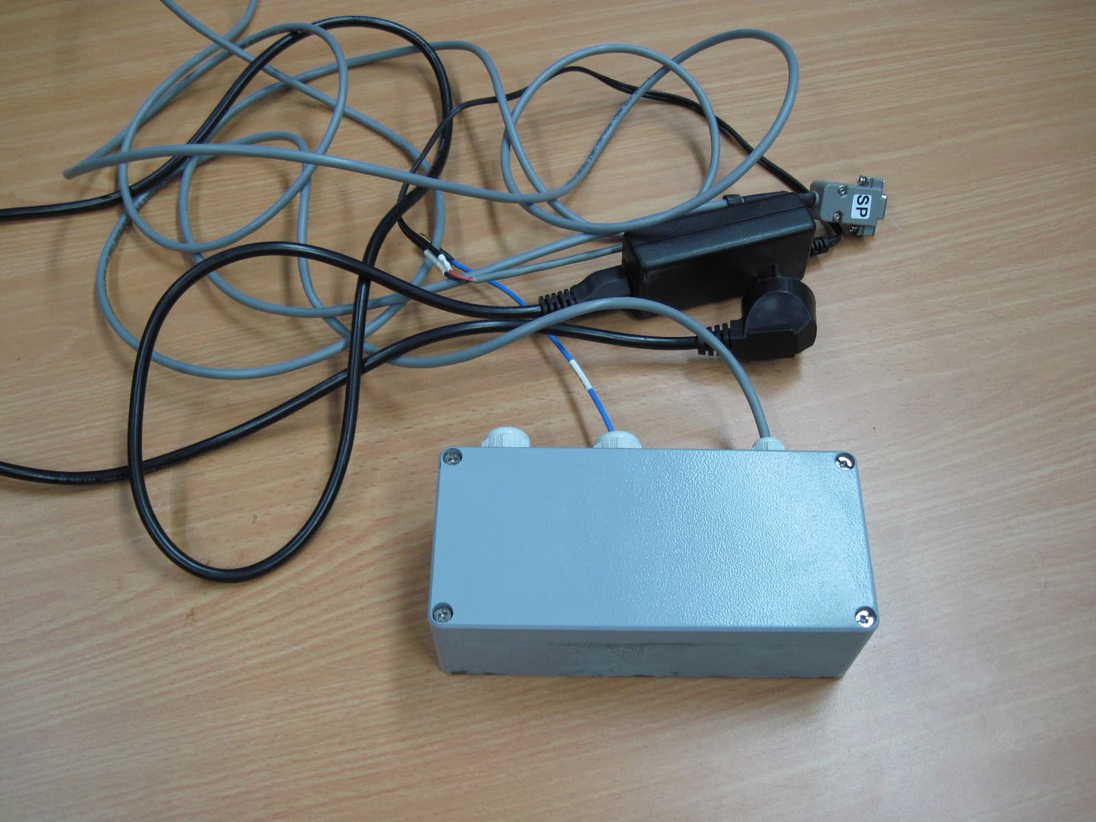
MLLGL3RPT450
Oct 28, 2010TRANSCEIVER 3A
Equipment Class
TNB - Licensed Non-Broadcast Station Transmitter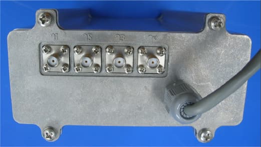
MLLGL2RPT150
Jan 14, 2006Repeater
Equipment Class
TNB - Licensed Non-Broadcast Station Transmitter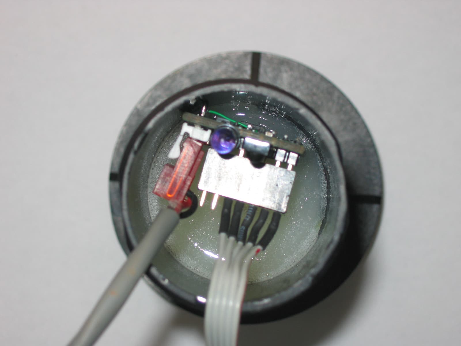
MLLGLXPT2
Sep 16, 2005Wireless Data Collection Transmitter
Equipment Class
TNB - Licensed Non-Broadcast Station Transmitter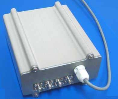
MLLGL2RPT450
Jan 23, 2005Repeater
Equipment Class
TNB - Licensed Non-Broadcast Station Transmitter
MLLIWCTX15-17
Dec 21, 2004Field Station
Equipment Class
TNB - Licensed Non-Broadcast Station Transmitter