MLLSPEEDHPRX450Licenced Non-Broadcast Transmitter
Miltel Communications Ltd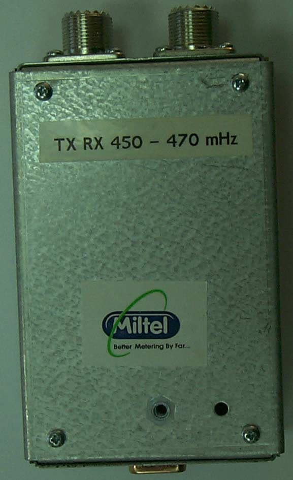
Click to zoom
Application Details
- Equipment Class
- TNB - Licensed Non-Broadcast Station Transmitter
- Date of Grant
- Feb 04, 2003
- Application Purpose
- Original Equipment
- Date of Application
- Feb 04, 2003
- Equipment Note
- Licenced Non-Broadcast Transmitter
- Frequency Range
- 450.00000000 - 470.00000000
- Company
- Miltel Communications Ltd
- Country
- Israel
Documents & Files
Document Text
Text extracted from the exhibit documents filed with the FCC. Open a document above to read the original.
Users Manual
Speed HPRx450 Wireless Data Link for Data Transfer FCC ID: MLLSPEEDHPRX450 User Manual Miltel Communications Ltd. December 2002 2 Table of Contents Chapter 1 Introduction .................................................................................................3 1.1 Purpose and Use ............................................................................................3 1.2 System General Description ...........................................................................3 1.3 Theory of Operation........................................................................................4 Chapter 2 Technical Characteristics................................................................................5 2.1 Technical Specification ...................................................................................5 2.1.1 Electrical .........................................................................................................5 2.1.2 Physical...........................................................................................................6 2.2 Label Contents................................................................................................6 Chapter 3 Installation Instructions ...................................................................................7 3.1 General ...........................................................................................................7 3.2 Installation.......................................................................................................7 3 Chapter 1 Introduction 1.1 Purpose and Use The Speed HPRx450 (FCC ID: MLLSPEEDHPRX450) is a data link transceiver that is used for data transfer in Miltel’s utility consumption readings collection system. This device is installed on-site by a professional field technician, thus it includes technical terms. The equipment is not to be installed by a non-professional individual that has not been trained and authorized. 1.2 System General Description The Speed HPRx450 system is a computerized fully automatic radio device. It requires no human intervention after initial installation. The device acts as a store- and-forward radio relay. The Speed HPRx450 captures any transmission from a Speed HPTx transmitter and, after validating the message, transmits the message again. The Speed HPRx450 relays information from meter reading transmitters to regional concentrators (which are equipped with a radio receiver). The concentrator transfers the data to the central computer for data collection and for further analysis and reporting. 4 1.3 Theory of Operation The Speed HPRx450 is the intermediate link in the meter readings data collection system. It is an independent unit that operates as a repeater (radio relay). Figure 2-1 (see below) shows a typical installation of a Speed HPRx450 unit. The device is powered by a 12 volt power supply or by a solar powered battery. The Speed HPRx450 operates its radio receiver on a continuous basis until it receives a message from a nearby transmitter. After capturing the transmitted data message, it sends out an identical message which is forwarded to the regional concentrator. Figure 1-1: Speed HPRx450 Typical Installation (shown here with optional solar panels) 5 Chapter 2 Technical Characteristics 2.1 Technical Specification 2.1.1 Electrical Max Effective Radiated Power (ERP) 43 mW (Complies with FCC 90.205(g) ) Output frequency 450-470 MHz Carrier wave modulation 2 Level FSK Power supply Lithium battery, 3.6 Volt Receiver Sensitivity -117 dbm 6 2.1.2 Physical Operating temperature -30°C ÷+50°C Water Resistance Splash resistance (IP-64) Length 16 cm. Width 12 cm. Depth 7.5 cm. Weight (excluding clamp) 650 gr. Weight (including clamp) 900 gr. Clamp material Stainless steel 2.2 Label Contents (see file: Speed HPRx450 ID Label) FCC ID: MLLSPEEDHPRX450 Model: Speed HPRx450 S/N: YY-nnnnnn Miltel Communications Ltd. Made in Israel Figure 2-1: Label Design 7 Chapter 3 Installation Instructions 3.1 General The Speed HPRx450 is installed by a professional technician. 3.2 Installation For on-site installation of the Speed HPRx450 device, proceed as follows: 1) Loosen the four screws fastening the unit's box and open the box cover. 2) Connect the 12 volt DC power supply (use only U/L approved power supply) 3) Install screws and mount to wall or to mast 4) Close case 5) Install antenna on a mast using the clamp provided Please Note: FCC RF exposure: Antenna Installation: The antenna(s) used for this transmitter must be installed to provide a separation distance of at least 20cm from all persons and must not exceed an antenna gain of 3 dBi. The antenna(s) used for this transmitter must not be co-located or operating in conjunction with any other antenna or transmitter. 6) Connect the Coax cable at both ends – to the repeater and to the antenna 7) Perform functional radio test by using a Speed HPTx transmitter. Verify that the message is relayed by the repeater to the concentrator. 8 Whenever possible, the repeater should be installed indoors. If outdoor installation is required, the repeater should be installed within a weatherized enclosure.
Cover Letter(s)
Correspondence Summary Questions & Answers SUBJECT: MILTEL COMMUNICATIONS LTD. FCC ID: MLLSPEEDHPRX450 Date: 01/22/2003 Q - 12. Part 2.1033(c)(8): The dc voltages applied to and dc currents into the several elements of the final radio frequency amplifying device for normal operation over the power range. A – 12 The dc voltage is 5V ±3%. The dc current is 40 mA. Q - 15. Part 90.203(e)(g) – Programming capability: Please, provide an attestation for compliance with this section. A – 15 The EUT is not programmable and all parameters are pre-set during the manufacturing process. Date: 02/04/2003 Q - 6 Temperature stability: Part 90.213 (footnote 7) states that the minimum frequency deviation is 1.5ppm for fixed and base stations (worst-case) operating on 12.5 kHz channel bandwidth. This transmitter does not comply with this requirement. Please, explain. A – 6 During the course of system installation and for a period of time thereafter, we recommend to our certified installers to operate the device in a mobile configuration until optimal coverage has been attained. This may occur over an extended period of time as the site is fully built out. Furthermore, it is our recommendation that placement of the repeater device is adjusted from time-to-time during the course of the year in order to ensure optimal radio coverage. Indeed, in many applications, the device is installed in a mobile configuration. As such, the EUT was tested with a minimum frequency deviation of 2.5 ppm operating a 12.5 KHz. bandwidth (Part 90.213). Q - 11. Part 2.1033(c)(6): Please provide range of operating power values or specific operating power levels, and description of any means provided for variation of operating power. A – 11 The output power is fixed.
Cover Letter(s)
Miltel Communications Ltd. 7 Leshem Street, 4 th Floor P.O. Box 7374 Petach Tikva, Israel 49170 Tel: 972-3-926-9550 Fax: 972-3-924-6550 16 December 2002 Federal Communications Commission Authorization and Evaluation Division Re: Miltel Communications, FCC ID: MLLSPEEDHPRX450, Ref #316IC2 Confidentiality Request Pursuant to sections 0.457 and 0.459 of the Commission’s rules, the Applicant hereby requests confidential treatment of information accompanying this Application as outlined below: Schematics Block Diagrams Operational Descriptions Parts List (BOM) The above materials contain trade secrets and proprietary information not customarily released to the public. The public disclosure of these matters might be harmful to the Applicant and provide unjustified benefits to its competitors. The Applicant understands that pursuant to Rule 0.457, disclosure of the Application and all accompanying documentation will not be made before the date of the Grant for this Application. Sincerely, Jack Graudenz Chairman
External Photos
FCC ID:MLLSPEEDHPRX450 Page 1 of 3 EXTERNAL PHOTOGRAPHS This document contains 2 photographs FCC ID:MLLSPEEDHPRX450 Page 2 of 3 Photograph No.1 SPEED HPRx450 front view FCC ID:MLLSPEEDHPRX450 Page 3 of 3 FCC ID:MLLSPEEDHPRX450 Page 4 of 3 Photograph No.2 SPEED HPRx450
ID Label/Location Info
Speed HPRx450 ID Label 1 ID Label The equipment label shown below is affixed to the Transmitter device on the bottom panel as depicted in the photos (see attached file – External_Photos Tx). FCC ID: MLLSPEEDHPRX450 Model: Speed HPRx450 S/N: YY-nnnnnn Miltel Communications Ltd. Made in Israel Label Dimensions: 60 mm. x 25 mm.
ID Label/Location Info
FCC ID:MLLSPEEDHPRX450 Page 4 of 3 Photograph No.2 SPEED HPRx450
Internal Photos
FCC ID:MLLSPEEDHPRX450 Page 1 of 4 INTERNAL PHOTOGRAPHS This document contains 4 photographs FCC ID:MLLSPEEDHPRX450 Page 2 of 4 Photograph No.1 SPEED HPRx450 internal view main PCB FCC ID:MLLSPEEDHPRX450 Page 3 of 4 Photograph No.2 SPEED HPRx450 internal view secondary PCB FCC ID:MLLSPEEDHPRX450 Page 4 of 4 Photograph No.3 SPEED HPRx450 rear view secondary PCB FCC ID:MLLSPEEDHPRX450 Page 5 of 4 Photograph No.4 SPEED HPRx450 rear view main PCB FCC ID:MLLSPEEDHPRX450 Page 6 of 4
Parts List/Tune Up Info
Speed HPRx450 Operational Description 1 Tune-Up Procedure The repeater device has three trimmers on the main PCB board and one trimmer on the secondary PCB board for adjusting and tuning the repeater frequency. All the other parameters (power, modulation bandwidth and timing) are pre-set to a fixed value and are not changeable or adjustable. The alignment procedure involves a setup that includes a power supply, a synthesized spectrum analyzer and a signal generator. First Alignment: The output signal is monitored on the spectrum analyzer with a scan- width of 20 KHz. The center of the modulated output waveform is adjusted using trimmer C7 on the secondary PCB board to within +/- 2 KHz. of the center frequency. This adjustment procedure is performed on the finished and complete unit as a final test before cover closure (after cover closure the repeater parameters are verified again). Second Alignment: The signal generator is set at the center frequency and is connected to the repeater antenna. The spectrum analyzer is set to 455 KHz, span 50 KHz, amplitude –30 dBm. The spectrum analyzer is connected to test point 6 (TP6). Trimmer C51C is used for fine tuning the frequency. Using trimmer C58B (on the main PCB board) adjust the BPF imageB filter to a maximum signal/noise ratio. The same procedure is repeated for trimmer C59B. This testing procedure is done while the repeater antenna is brought to the proximity of a wire antenna connected to the spectrum analyzer.
RF Exposure Info
FCC ID:MLLSPEEDHPRX450 Repeater, model Speed HPRx450 Exposure limit according to §1.1310 Limit for power density for general population/uncontrolled exposure is f/1500 mW/cm 2 for 300 – 1500 MHz frequency range. For 450 MHz the power density is equal to 450/1500 = 0.3 mW/cm 2 For 470 MHz the power density is equal to 470/1500 = 0.313 mW/cm 2 The power density P (mW/cm 2 ) = P T / 4π ππ π r 2 , i.e. 0.3 mW/cm 2 = P T / 4π ππ π r 2 , where P T is the transmitted power, which is equal to the transmitter output power 16.33 dBm plus maximum antenna gain 3 dBi, the maximum equivalent isotropically radiated power EIRP is P T = 16.33 dBm +3 dBi = 19.33 dBm = 85.7 mW. The minimum safe distance “r”, where RF exposure does not exceed FCC permissible limit, is 4.77 cm: r = sqrt (P T / (Px4π)) = sqrt (85.7/ 0.3 x 4 x 3.14) = 4.77 cm The public cannot be exposed to dangerous RF level.
Test Report
Test Report_450-470_rev2 Date: January, 2003 Page 1 of 108 ELECTROMAGNETIC EMISSIONS TEST REPORT ACCORDING TO FCC CFR 47 PART 15 SUBPART B, PART 90 SUBPART I for Miltel Communications Ltd. EQUIPMENT UNDER TEST: Transmitter of automatic meter reading system, model MLLSpeed HPRx450 Test Report_450-470_rev2 Date: January, 2003 Page 2 of 108 Description of equipment under test Test items Transmitter of automatic meter reading system Manufacturer Miltel Communications Ltd. Types (Models) MLLSpeed HPRx450 Receipt date August 18, 2002 Applicant information Applicant’s representative Mr. Erez Sharabi, V.P. engineering Applicant’s responsible person Mr. Yarum Locker, C.E.O. Company Miltel Communications Ltd. Address 7 Leshem street P.O.Box 7374 Postal code 49170 City Petach Tikva Country Israel Telephone number +972 3926 9550 Telefax number +972 3924 6550 Test performance Test started August 18, 2002 Test completed October 20, 2002 Test specification(s) FCC part 90 subpart I, §§90.205, 90.209, 90.210, 90.213; 90.214; part 15 subpart B §15.109; subpart C §15.207 Test Location: Hermon Laboratories Ltd. Certified Test Facilities Test Report_450-470_rev2 Date: January, 2003 Page 3 of 108 Contents 1 Summary and signatures ..........................................................................................4 2 General information ...................................................................................................5 2.1 Abbreviations and acronyms .......................................................................................5 2.2 Specification references...............................................................................................5 2.3 EUT description ...........................................................................................................6 2.4 EUT test configuration .................................................................................................6 3 Emissions measurements.........................................................................................7 3.1 Effective radiated power measurements according to FCC part 90 paragraph 205(g)7 3.2 Occupied bandwidth measurements according to FCC part 90 paragraph 209 .......11 3.3 Emission mask according to FCC part 90 paragraph 210(d) ....................................15 3.4 Frequency stability measurements according to FCC part 90 paragraph 213 ..........78 3.5 Transient frequency behavior according to FCC part 90 paragraph 214 ..................85 3.6 Radiated emission measurements according to FCC part 15 subpart B §15.109 ....94 3.7 Mains terminal radio interference voltage measurements.......................................100 APPENDIX A - Test equipment and ancillaries used for tests .......................................106 APPENDIX B-Test equipment correction factors ............................................................108 Test Report_450-470_rev2 Date: January, 2003 Page 4 of 108 1 Summary and signatures The EUT, MLLSpeed HPRx450 transmitter of automatic meter reading system, was tested according to FCC part 90 subpart I, §§90.205, 90.209, 90.210, 90.213, 90.214; part 15 subpart B §15.109, subpart C §15.207 and found to comply with the §90.213 of the standard requirements. Test description Specification reference Test report paragraph Pass / Fail RF output power 90.205, 2.1046 3.1 Pass Occupied bandwidth 90.209 2.1049 3.2 Pass Emission mask 90.210(d) 3.3 Pass Conducted spurious emissions 90.210(d) 2.1051 3.3 Pass Radiated spurious emissions 90.210(d) 2.1053 3.3 Pass Frequency stability vs temperature 90.213 2.1055 3.4 Pass Frequency stability vs voltage 2.1055 3.5 Pass Transient frequency behavior 90.214 3.6 Pass Conducted emissions 15.207 3.7 Pass Radiated emissions 15.109 3.8 Pass Test Report_450-470_rev2 Date: January, 2003 Page 5 of 108 2 General information 2.1 Abbreviations and acronyms The following abbreviations and acronyms are applicable to this test report: cm centimeter dB decibel dBm decibel referred to one milliwatt dB(μV) decibel referred to one microvolt dB(μV/m) decibel referred to one microvolt per meter DC direct current EMC electromagnetic compatibility EUT equipment under test GHz gigahertz H height Hz hertz kHz kilohertz kV kilovolt L length m meter MHz megahertz mW milliwatt NA not applicable PC personal computer QP quasi-peak (detector) RE radiated emission rms root-mean-square sec second V volt W watt 2.2 Specification references CFR 47 part 15: 10/2002 Radio Frequency Devices CFR 47 part 90: 10/2001 Private land mobile radio services, Subpart I ANSI C63.2:06/1996 American National Standard for Instrumentation- Electromagnetic Noise and Field Strength, 10 kHz to 40 GHz-Specifications. ANSI C63.4:1992 American National Standard for Methods of Measurement of Radio-Noise Emissions from Low- Voltage Electrical and Electronic Equipment in the Range of 9 kHz to 40 GHz. Test Report_450-470_rev2 Date: January, 2003 Page 6 of 108 2.3 EUT description The EUT, MLLSpeed HPRx,450 is a data link transceiver operating in 450 – 470 MHz. The channel separation is 12.5 kHz, fast frequency shift key (FFSK) type of modulation is used. The device utilizes the same antenna connector for transmitter and receiver and is powered by 120 V AC/12 V DC adapter. The EUT operating frequencies generated by clocks are 3.5795 MHz, 4.0 MHz, 10.245 MHz, 13.2256 MHz, 20.0 MHz, by local oscillator – 458.9 MHz. 2.4 EUT test configuration The EUT ports and lines description is given in Table 2.4.1, test configuration is shown in Figure 2.4.1. Table 2.4.1 EUT ports and lines Port type Port description Connector type Quantity Cable type description Cable length, m Connected to Power DC power D-type, 9 pin 1 Unshielded 1 Adapter Control Frequency change As above Unshielded 0.2 Push-button Signal RF UHF 2 Coax 50 Ω NA Termination Figure 2.4.1 EUT test configuration EUT Push- button Adapter Coax 50 Ohm terminations AC mains12 V DC Test Report_450-470_rev2 Date: January, 2003 …
Text truncated - open the document above for the full version.
Test Report
DATATo VCO C116A NI 2 1 R45A 1M 1 2 R32A 5.1k 1 2 C97A 1n 2 1 R41A 1M 1 2 R44A 10k 1 2 R56A 0 1 2 R_1A 7.5k 1 2 D2A LM4041EIM3X-1.2 2 1 3 V D2A x R_1A x R32A V max = (R45 + R_1A) x (R41A + R32A) 1.2V x 7.5K x 5.1K V max = = 0.0453 mV (1M + 7.5K) x (1M + 5.1K) The VCO Pulling 12000 KHz/V BW -3dB max = (2.4 x 2) + (0.0000453 x 12000KHz x 2) = 5.88KHz
Contact Information
Applicant
Yarum Locker(General Manager)
Test Firm
Hermon Laboratories Ltd.Alexander Usoskin
Technical Specifications
| # | Rule Parts | Frequency Range | Power Output | Emission | Tolerance |
|---|---|---|---|---|---|
| 1 | 90 | 450 MHz - 470 MHz | 43.00 mW | 5K99F1D | 2.5000000000 ppm |
Other Applications from Miltel Communications Ltd
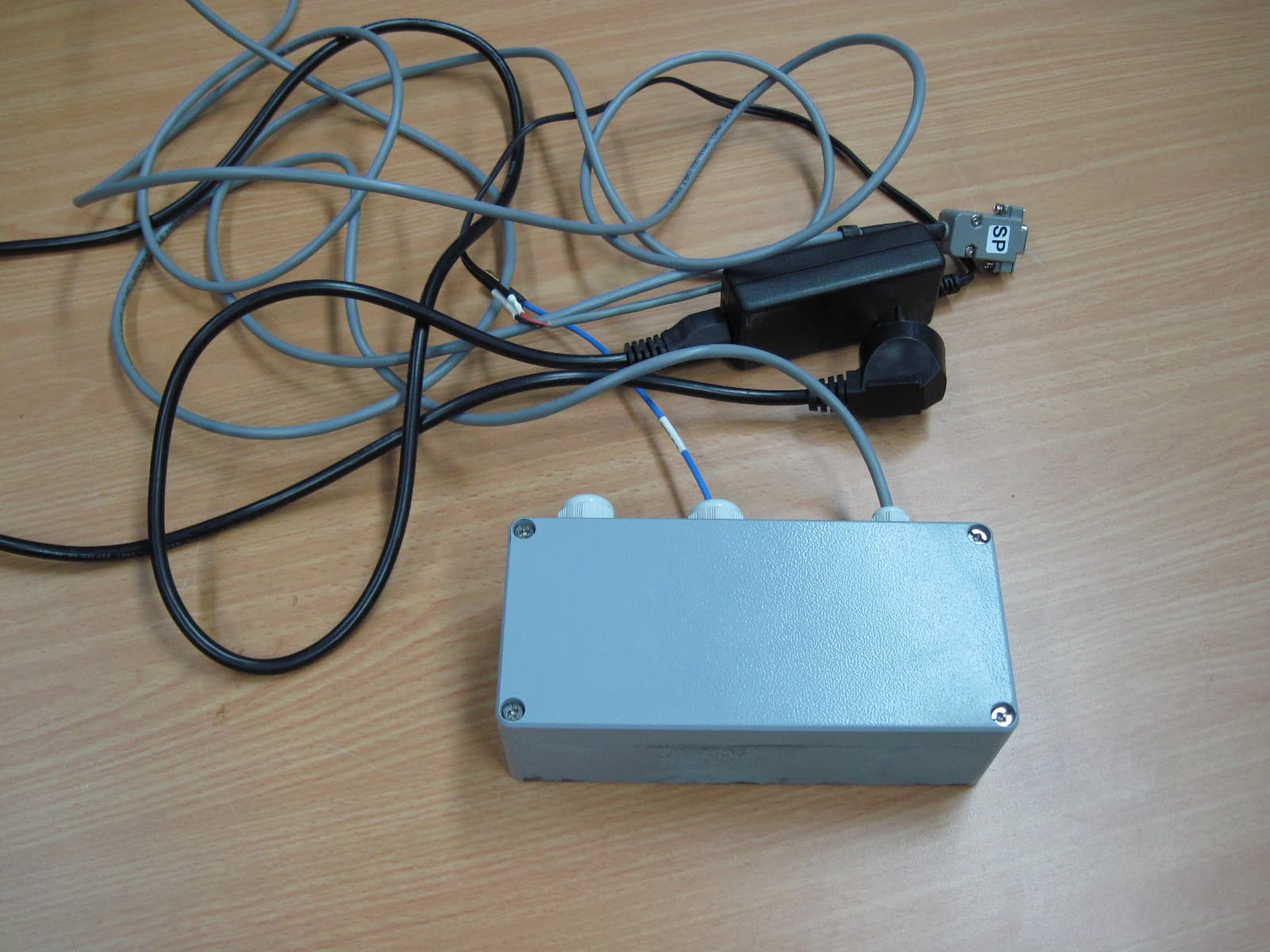
MLLGL3RPT450
Oct 28, 2010TRANSCEIVER 3A
Equipment Class
TNB - Licensed Non-Broadcast Station Transmitter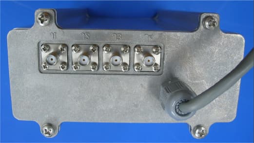
MLLGL2RPT150
Jan 14, 2006Repeater
Equipment Class
TNB - Licensed Non-Broadcast Station Transmitter
MLLGLXPT2
Sep 16, 2005Wireless Data Collection Transmitter
Equipment Class
TNB - Licensed Non-Broadcast Station Transmitter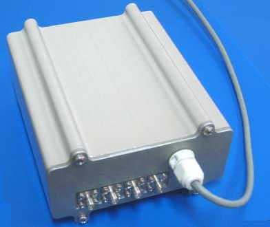
MLLGL2RPT450
Jan 23, 2005Repeater
Equipment Class
TNB - Licensed Non-Broadcast Station Transmitter
MLLIWCTX15-17
Dec 21, 2004Field Station
Equipment Class
TNB - Licensed Non-Broadcast Station Transmitter