MLLSPEEDHPTX15-17Transmitter for an automatic meter reading system
Miltel Communications Ltd
Click to zoom
Application Details
- Equipment Class
- TNB - Licensed Non-Broadcast Station Transmitter
- Date of Grant
- May 06, 2001
- Application Purpose
- Original Equipment
- Date of Application
- Feb 07, 2001
- Equipment Note
- Transmitter for an automatic meter reading system
- Frequency Range
- 150.00000000 - 174.00000000
- Company
- Miltel Communications Ltd
- Country
- Israel
Documents & Files
Document Text
Text extracted from the exhibit documents filed with the FCC. Open a document above to read the original.
Users Manual
Speed HPTx Wireless Data Link for Meter Reading FCC ID: MLLSPEEDHPTX15-17 User Manual Miltel Communications Ltd. January 2001 Table of Contents Chapter 1 Introduction ................................................................................................ 4 1.1 Purpose and Use........................................................................................ 4 1.2 System General Description........................................................................ 4 Chapter 2 Theory of Operation.................................................................................... 5 2.1 General Description .................................................................................... 5 2.2 Block Diagram Description .......................................................................... 7 2.2.1 General ...................................................................................................... 7 2.2.1 Digital Section ............................................................................................ 8 2.2.3 RF Section ................................................................................................. 9 Chapter 3 Technical Characteristics...........................................................................10 3.1 Technical Specification ..............................................................................10 3.1.1 Electrical ...................................................................................................10 3.1.2 Physical.....................................................................................................10 3.2 Label Contents ..........................................................................................11 Chapter 4 Installation Instructions..............................................................................12 4.1 General .....................................................................................................12 4.2 Installation .................................................................................................12 NOTICE This equipment has been tested and found to comply with the limits for a Class B digital device, pursuant to part 15 of the FCC Rules. These limits are designed to provide reasonable protection against harmful interference in a residential installation. This equipment generates, uses and can radiate radio frequency energy and, if not installed and used in accordance with the instructions, may cause harmful interference to radio communications. However, there is no guarantee that interference will not occur in a particular installation. If this equipment does cause harmful interference to radio or television reception, which can be determined by turning the equipment off and on, the user is encouraged to try to correct the interference by one or more of the following measures: -Reorient or relocate the receiving antenna. -Increase the separation between the equipment and receiver. -Connect the equipment into an outlet on a circuit different from that to which the receiver is connected. -Consult the dealer or an experienced radio/TV technician for help. Chapter 1 Introduction 1.1 Purpose and Use The Speed HPTx ( FCC ID: MLLSPEEDHPTX15-17 ) is a data link transmitter that is used for data acquisition in Miltel’s water consumption readings collection system. This device is installed on-site by a professional field technician, thus it includes technical terms. The equipment is not to be installed by a non-professional individual. 1.2 System General Description The Speed HPTx system is a computerized fully automatic radio device. It requires no human intervention after initial installation. The system enables remote, continuous and accurate reading of water consumption. The Speed HPTx transmits the data acquired from water meters to a regional. The concentrator transfers the data to the central computer for data collection and for further analysis and reporting. Chapter 2 Theory of Operation 2.1 General Description The Speed HPTx is the first link in the water readings collection system. It is an independent unit that does not require an external power source, wiring, or the preparation of an infrastructure. The unit is installed in proximity to the water meter/s and is connected to several adjacent meters. Figure 2-1 (see next page) shows a typical installation of a Speed HPTx unit, connected to several meters (of various types) at a single location. The unit can be connected to any type of meter which has a pulsed output (a passive magnetic open/short reed relay). The Speed HPTx acquires the consumption data from the water meters and stores this data in its memory. The unit includes a miniature RF transmitter which transmits data on a periodic basis to a regional concentrator. Figure 2-1: Speed HPTx Typical Installation 2.2 Block Diagram Description 2.2.1 General Figure 2-2 describes the block diagram of the Speed HPTx unit. This device consists of two major sections, all using a common power source: ! Digital section (Micro Controller) ! RF section Transmitter ( Speed Clamp A 3.6 volts Lithium battery provides power to all parts of the device. The power supply for the RF section is controlled via the Tx switch (not shown), thus cutting of power to the transmitter unless necessary for actual data transmission (standby mode). Figure 2-2: Speed HPTx Block Diagram Meter 1 Meter n Sensing and Support Circuitry Micro- Controller RF Transmitter Antenna Battery Device Enclosure Magnetic Switch Tamper Switch 2.2.2 Digital Section The digital section of the Speed HPTx performs the following functions: ! Samples reed switches to detect short/open from each meter. ! Accumulates number of pulses for each meter separately ! Stores data (including battery and tamper alarms) and stores information internal memory ! Interfaces the data to the RF section The digital section is based on a central controller which accepts the following inputs: a.Analog inp…
Text truncated - open the document above for the full version.
Users Manual
Speed HPTx Wireless Data Link for Meter Reading FCC ID: MLLSPEEDHPTX15-17 User Manual Miltel Communications Ltd. January 2001 Table of Contents Chapter 1.................................................................................................Introduction 4 1.1 Purpose and Use........................................................................................ 4 1.2 System General Description........................................................................ 4 Chapter 2 Theory of Operation.................................................................................... 5 2.1 General Description .................................................................................... 5 2.2 Block Diagram Description .......................................................................... 7 2.2.1 .......................................................................................... General .............................................................................................................. 7 2.2.1 ................................................................................. Digital Section .............................................................................................................. 8 2.2.3 ...................................................................................... RF Section .............................................................................................................. 9 Chapter 3 Technical Characteristics...........................................................................10 3.1 Technical Specification ..............................................................................10 3.1.1 ......................................................................................... Electrical .............................................................................................................10 3.1.2 .......................................................................................... Physical .............................................................................................................10 3.2 Label Contents ..........................................................................................11 Chapter 4 Installation Instructions..............................................................................12 4.1 General .....................................................................................................12 4.2 Installation .................................................................................................12 - - Chapter 1 Introduction 1.1 Purpose and Use The Speed HPTx ( FCC ID: MLLSPEEDHPTX15-17 ) is a data link transmitter that is used for data acquisition in Miltel’s water consumption readings collection system. This device is installed on-site by a professional field technician, thus it includes technical terms. The equipment is not to be installed by a non-professional individual. 1.2 System General Description The Speed HPTx system is a computerized fully automatic radio device. It requires no human intervention after initial installation. The system enables remote, continuous and accurate reading of water consumption. The Speed HPTx transmits the data acquired from water meters to a regional. The concentrator transfers the data to the central computer for data collection and for further analysis and reporting. Chapter 2 Theory of Operation 2.1 General Description The Speed HPTx is the first link in the water readings collection system. It is an independent unit that does not require an external power source, wiring, or the preparation of an infrastructure. The unit is installed in proximity to the water meter/s and is connected to several adjacent meters. Figure 2-1 (see next page) shows a typical installation of a Speed HPTx unit, connected to several meters (of various types) at a single location. The unit can be connected to any type of meter which has a pulsed output (a passive magnetic open/short reed relay). The Speed HPTx acquires the consumption data from the water meters and stores this data in its memory. The unit includes a miniature RF transmitter which transmits data on a periodic basis to a regional concentrator. Figure 2-1: Speed HPTx Typical Installation 2.2 Block Diagram Description 2.2.1 General Figure 2-2 describes the block diagram of the Speed HPTx unit. This device consists of two major sections, all using a common power source: ! Digital section (Micro Controller) ! RF section Transmitter ( Speed Clamp A 3.6 volts Lithium battery provides power to all parts of the device. The power supply for the RF section is controlled via the Tx switch (not shown), thus cutting of power to the transmitter unless necessary for actual data transmission (standby mode). Figure 2-2: Speed HPTx Block Diagram Meter 1 Meter n Sensing and Support Circuitry Micro- Controller RF Transmitter Antenna Battery Device Enclosure Magnetic Switch Tamper Switch 2.2.2 Digital Section The digital section of the Speed HPTx performs the following functions: ! Samples reed switches to detect short/open from each meter. ! Accumulates number of pulses for each meter separately ! Stores data (including battery and tamper alarms) and stores information internal memory ! Interfaces the data to the RF section The digital section is based on a central controller which accepts the following inputs: a.Analog inputs (from reed-relay contacts) designated INPUT1 through INPUTn, each indicating the advance of a single water meter. These are the only inputs of the controller which are connected to the external source. b.Magnetic switch input is utilized only for test. c.The TAMPER SWITCH input is connected to a micro-switch that senses an opening of the unit's box. This enables the Speed HPTx to generate and transmit an alarm signal in the event of unauthorized opening of the unit casing. d.The LOW VOLTAGE input of the controller is connected to battery via a Low Voltage Detecto…
Text truncated - open the document above for the full version.
Users Manual
Speed HPTx Wireless Data Link for Meter Reading FCC ID: MLLSPEEDHPTX15-17 User Manual Miltel Communications Ltd. January 2001 Table of Contents Chapter 1.................................................................................................Introduction 4 1.1 Purpose and Use........................................................................................ 4 1.2 System General Description........................................................................ 4 Chapter 2 Theory of Operation.................................................................................... 5 2.1 General Description .................................................................................... 5 2.2 Block Diagram Description .......................................................................... 7 2.2.1 .......................................................................................... General .............................................................................................................. 7 2.2.1 ................................................................................. Digital Section .............................................................................................................. 8 2.2.3 ...................................................................................... RF Section .............................................................................................................. 9 Chapter 3 Technical Characteristics...........................................................................10 3.1 Technical Specification ..............................................................................10 3.1.1 ......................................................................................... Electrical .............................................................................................................10 3.1.2 .......................................................................................... Physical .............................................................................................................10 3.2 Label Contents ..........................................................................................11 Chapter 4 Installation Instructions..............................................................................12 4.1 General .....................................................................................................12 4.2 Installation .................................................................................................12 - - Chapter 1 Introduction 1.1 Purpose and Use The Speed HPTx ( FCC ID: MLLSPEEDHPTX15-17 ) is a data link transmitter that is used for data acquisition in Miltel’s water consumption readings collection system. This device is installed on-site by a professional field technician, thus it includes technical terms. The equipment is not to be installed by a non-professional individual. 1.2 System General Description The Speed HPTx system is a computerized fully automatic radio device. It requires no human intervention after initial installation. The system enables remote, continuous and accurate reading of water consumption. The Speed HPTx transmits the data acquired from water meters to a regional. The concentrator transfers the data to the central computer for data collection and for further analysis and reporting. Chapter 2 Theory of Operation 2.1 General Description The Speed HPTx is the first link in the water readings collection system. It is an independent unit that does not require an external power source, wiring, or the preparation of an infrastructure. The unit is installed in proximity to the water meter/s and is connected to several adjacent meters. Figure 2-1 (see next page) shows a typical installation of a Speed HPTx unit, connected to several meters (of various types) at a single location. The unit can be connected to any type of meter which has a pulsed output (a passive magnetic open/short reed relay). The Speed HPTx acquires the consumption data from the water meters and stores this data in its memory. The unit includes a miniature RF transmitter which transmits data on a periodic basis to a regional concentrator. Figure 2-1: Speed HPTx Typical Installation 2.2 Block Diagram Description 2.2.1 General Figure 2-2 describes the block diagram of the Speed HPTx unit. This device consists of two major sections, all using a common power source: ! Digital section (Micro Controller) ! RF section Transmitter ( Speed Clamp A 3.6 volts Lithium battery provides power to all parts of the device. The power supply for the RF section is controlled via the Tx switch (not shown), thus cutting of power to the transmitter unless necessary for actual data transmission (standby mode). Figure 2-2: Speed HPTx Block Diagram Meter 1 Meter n Sensing and Support Circuitry Micro- Controller RF Transmitter Antenna Battery Device Enclosure Magnetic Switch Tamper Switch 2.2.2 Digital Section The digital section of the Speed HPTx performs the following functions: ! Samples reed switches to detect short/open from each meter. ! Accumulates number of pulses for each meter separately ! Stores data (including battery and tamper alarms) and stores information internal memory ! Interfaces the data to the RF section The digital section is based on a central controller which accepts the following inputs: a.Analog inputs (from reed-relay contacts) designated INPUT1 through INPUTn, each indicating the advance of a single water meter. These are the only inputs of the controller which are connected to the external source. b.Magnetic switch input is utilized only for test. c.The TAMPER SWITCH input is connected to a micro-switch that senses an opening of the unit's box. This enables the Speed HPTx to generate and transmit an alarm signal in the event of unauthorized opening of the unit casing. d.The LOW VOLTAGE input of the controller is connected to battery via a Low Voltage Detecto…
Text truncated - open the document above for the full version.
Block Diagram
Speed HPTxBlock Diagram1 Transmitter Block Diagram Diagram 1 - RF Section Block Diagram (also see separately attached schematics) Me te r Me te r Sensing and Support Circuitry Micro- Controller RF Transmitter Antenna Battery Device Enclosure Magnetic Test Switch Tamper Switch Integral Wire Antenna Internal Test Port - - - C C C o o o n n n f f f i i i d d d e e e n n n t t t i i i a a a l l l - - - Speed HPTxBlock Diagram2 Diagram 2 – Transmitter’s RF Section Block Diagram A PLL IC ( LMX1601 from National Semiconductors) gets the reference from a crystal oscillator and locks the VCO output to the crystal frequency. The VCO is a derivative of a Colpitts varactor tuned oscillator. NE85633 is the oscillator transistor. The VCO output is amplifiered by a RF amplifier. The output is further filtered by a 6 poles low pass filter that rejects the harmonics. - - - C C C o o o n n n f f f i i i d d d e e e n n n t t t i i i a a a l l l - - - From Controller Phase Locked Loop (PLL) Crystal 20 MHz Voltage Controlled Oscillator (VCO) To Antenna Amplifier and Low Pass Harmonic Filter Reference Freque ncy Modulation In 150-170 MHz Speed HPTxBlock Diagram3 Transmitter Block Diagram VCO PLL CPU PROM RAM LP F BAT.S EN S PWR CONTROL LOOP FI LTER PWR CONTROL SP LI TER LP F CRISTAL INPUTS RF OUT DATA CLK RAM RF IN C.P DATD IN AMP
Cover Letter(s)
FEDERAL COMM UNICATIONS COMMISSION EQUIPMENT APPROVAL SERVICES P.O.B. 358315 Pittsburgh, PA 15251-5315 USA Subject: Application for certification of Speed HPTx transmitter, FCC ID:MLLSPEEDHPTX15-17 Dear Gentleme n, Please find attached our application for certification of Speed HPTx transmitter, FCC ID: MLLSPEEDHPTX15-17 , prepared in accordance with FCC Rules, parts 90, 2 and 15. The product testing and this application for certification were performed by Hermon Laboratories, which is listed by FCC. Hermon Labs responsible person is Dr. Edward Usoskin, tel: 011 972 4628 8001, fax:011 972 4628 8277, e-mail: [email protected] We hope this application satisfies your requirements Sincerely yours Mr. Yarum Locker, General Manager
Cover Letter(s)
FEDERAL COMM UNICATIONS COMMISSION APPLICATION PROCESSI NG BRANCH 7435 Oakland Mills Road Columbia, MD 21046 USA Subject: Request for confidentiality of Speed HPTx transmitter, FCC ID:MLLSPEEDHPTX15-17 Confirmation Number: EA99996 Dear Gentleme n, We apply to you with request to withhold Miltel Communications Ltd. trade secret in Application for Certification for FCC ID: MLLSPEEDHPTX15-17. These trade secrets can be found in the Speed HPTx transmitter schematic diagram (3 pages of this Application). Many thanks in aadvance. The required fee $145.00 is included in Form 159 sent to Mellon Bank on March 4, 2001. Sincerely yours Mr. Yarum Locker, General Manager
External Photos
Spees Tx External PhotosPage 1 of 3 Speed Tx - External Photos (side 1) Spees Tx External PhotosPage 2 of 3 Speed Tx - External Photos (side 2) Spees Tx External PhotosPage 3 of 3 Typical Installation
ID Label/Location Info
Speed HPTxID Label 1 ID Label The equipment label shown below is affixed to the Transmitter device on the side panel as depicted in the photos (see attached file – External_Photos Tx). FCC ID: MLLSPEEDHPTX15-17 Model: Speed HPTx S/N: YY-nnnnnn Miltel Communications Ltd. Made in Israel This device complies with Part 15 of the FCC rules. Operation is subjected to the following two conditions: (1) This device may not cause harmful interference, and (2) this device must accept any interference that may cause undesired operation. Label Dimensions: 60 mm. x 25 mm. Label Location: Transmitter side panel
ID Label/Location Info
Speed HPTxID Label 1 ID Label The equipment label shown below is affixed to the Transmitter device on the side panel as depicted in the photos (see attached file – External_Photos Tx). FCC ID: MLLSPEEDHPTX15-17 Model: Speed HPTx S/N: YY-nnnnnn Miltel Communications Ltd. Made in Israel This device complies with Part 15 of the FCC rules. Operation is subjected to the condition that this device does not cause harmful interference. Label Dimensions: 60 mm. x 25 mm. Label Location: Transmitter side panel
ID Label/Location Info
Speed HPTxID Label 1 ID Label The equipment label shown below is affixed to the Transmitter device on the side panel as depicted in the photos (see attached file – External_Photos Tx). FCC ID: MLLSPEEDHPTX15-17 Model: Speed HPTx S/N: YY-nnnnnn Miltel Communications Ltd. Made in Israel Label Dimensions: 60 mm. x 25 mm. Label Location: Transmitter side panel
Internal Photos
Speed Tx - Internal Photos Transmitter Antenna Lithium Battery Back of Transmitter Board
Operational Description
Speed HPTxOpe ratio nal De scriptio n 1 Technical Operational Description Introduction The Speed HPTx device is operated under FCC part 90 provision. The battery- operated transmitter can be connected to several meters (e.g. water) in parallel. The pulses generated by the Meters (Typically, one Pulse per second) are counted by the Micro-Controller, advancing an internal counter related to each Meter. The Counters information is transmitted at regular intervals. The transmitter includes a manual anti-tampering switch that generates a single transmission (Duration< 0.8Sec) when an intruder ille gally tries to open the cover. A magnetic switch inside the unit allows a professional installer to manually check the system’s integrity by initiating a single Transmission (Duration<0.8Sec) with a strong magnet attached to the unit. The Transmitter is enclosed in a plastic enclosure. An integral wire antenna soldered to the internal Printed Circuit Board is used. An internal 3.6 V Lithium battery powers the unit. Transmission Duration and Duty Cycle Typically every 4Hrs, or upon a consumption criteria, but not at intervals of less than 30 minutes , all the counters are transmitted in a single Transmission. The duration of each Transmission is less than 0.8 Sec . The transmission duration and duty cycle is hardware programmed (burnt in) into the Controller at the manufacturing phase and can not be modified later on. Specific Operating Power Level The power level of the transmitter is limited with a RF amplifier limiter (see block diagram) to value of 100 mW (20 dBm) and this power is less than 1 Watt (30 dBm) (Complies with FCC 90 .205 (d)). - CONFIDENTIAL - Speed HPTxOpe ratio nal De scriptio n 2 Tune-Up Information The transmitter device has only one trimmer (see C7 in RF section of transmitter schematics) for adjusting and tuning the output frequency. All the other parameters (power, modulation bandwidth and timing) are pre-set to a fixed value and are not changeable or adjustable. The alignment procedure involves a setup that includes a synthesized spectrum analyzer. The output signal is monitored on the spectrum analyzer with a scan-width of 20 KHz.. The center of the modulated output waveform is adjusted to within +/- 2 KHz. of the center frequency. This adjustment procedure is performed on the finished and complete unit as a final test before cover closure (after cover closure the transmitter parameters are verified again). This testing procedure is done while the transmitter antenna is brought to the proximity of a wire antenna connected to the spectrum analyzer. Emission and Modulation Description The transmitter is a constant envelop 2 level FSK with an FFSK sub-carrier. The peak-to-peak frequency deviation is 20KHz. The ITU Emission designation is: F1D. Complete System Description The Transmitter, which is described in this report, is a part of a complete AMR system (Automatic Meter Reading). The system components are: ComponentsModelDescriptionRequired FCC authorization Transmitter Speed HPTx Intentional Radiator Part 90 subpart C Certification Reciever Speed TRD Intentional Radiator Part 90 subpart C Verification ConcentratorCML20 (110)Digital Device class B Part 15 subpart B Verification Speed HPTxOpe ratio nal De scriptio n 3 Schematic Diagram Circuitry 1. Frequency stability The LM56 is a thermostat device. This component controls the voltage level on the varicap (changes in voltage level, cause the varicap to change its capaciy) . This technique allows to maintain the crystals natural frequency. 2. Spurious Suppression The L.P.F. (low pass filter) suppresses the spurious with zeros and poles. RF AmplifierLPF Clear mod ulation signal output Mod ulation signal input LM56 (Ther mosta t) Varicap in paralel to variable capacitor Crystal 20MHz to PLL Vo ltage Referen Vo ltage Level Speed HPTxOpe ratio nal De scriptio n 4 3. Modulation limiting To limit the modulation, a Zener Diode sets a stable voltage in the input to the VCO (volt control oscillator). 4. Power limiting The power level of the SpeedHPTx transmitter is limited with a RF amplifier limiter (see block diagram) to the value of 100 mW (+20dBm). Transistor (Q3) in the schematics acts as a SWITCH. Whenever the consumption of VCC2 increases, the Transistor (Q3) cut off supply voltage to RF amplifier (Q4). Stable voltage VCO Data In Limit unit of the mod ulation Loop Filter RF Amplifier Limiter Signal mod ulation input Signal modulation output (limit to 100mW / +20 dBm)
Parts List/Tune Up Info
Speed HPTxParts List 1 Speed TRANSMITTER 150-170MHz Revised: Thursday, 25,01,2001 SPEEDHPTX - CONFIDENTIAL - MILTEL COMMUNICATIONS LTD. Item Quantity Reference Part ______________________________________________ 1 6 C10,C15,C18,C21,C24,C? 470pF 2 3 C1,C14,C17 10nF 3 15 Y2,R2,C2,R3,C3,R4,R5,R22, N.U. R23,R24,R25,C25,R28,R30, R32 4 3 C4,C16,C28 1uF 5 3 C5,C6,C22 100nF 6 1 C7 (6-30)pF 7 1 C8 22pF 8 1 C9 68pF 9 4 C11,C12,C13,C29 10pF 10 1 C19 150nF 11 1 C20 100pF 12 3 C23,C26,C33 27pF 13 1 C27 2.7nF 14 1 C30 18pF 15 1 C31 33pF 16 1 C32 2pF 17 1 C34 6pF 18 1 C35 15pF 19 1 C36 N.U 20 2 C38,C37 1nF 21 1 D1 LM4040DIM3-2.5 22 2 D3,D2 BB833 23 1 D4 LM4041EIM3X-1.2 24 2 J3,J1 CON2AP 25 1 J2 ANT 26 1 J4 CON20 27 1 J5 CON7 28 3 L1,L2,L6 180nH 29 1 L3 8.2nH 30 1 L4 56nH 31 1 L5 39nH 32 1 L7 33nH 33 1 O1 VCO_CASE 34 2 Q1,Q3 MMBT2907 35 1 Q2 2N2222 36 2 Q4,Q5 NE85633 37 1 R1 180K 38 4 R6,R7,R8,R9 51.1k 39 4 R10,R11,R12,R13 47.5k 40 4 R14,R15,R16,R17 22.1k 41 4 R18,R19,R20,R21 61.9k 42 4 R26,R29,R51,R63 10k 43 5 R27,R40,R41,R42,R56 1k 44 2 R31,R33 2.2k 45 1 R34 3.3K 46 2 R35,R36 20K Speed HPTxParts List 2 47 1 R37 39K 48 1 R38 1.3K 49 1 R39 30K 50 1 R43 5.1K 51 6 R44,R49,R53,R54,R60,R61 18 52 2 R55,R45 51 53 2 R46,R47 10 54 3 R48,R50,R59 4.7k 55 1 R52 1.5K 56 2 R57,R58 100 57 2 R64,R62 1M 58 1 R65 22K 59 1 S1 SW 60 1 S2 KSK1A71/7-1324 61 1 U1 PIC16LC715 62 1 U2 MC34164P-003 63 1 U3 LM56 64 1 U4 LMX1601 65 1 Y1 3.111MHz 66 1 Y1A1 20MHz
Test Report
Test Report: 135728 Date: January, 2001 FCC ID: MLLSPEEDHPTX15-17 Page 1 of 49 HERMON LABORATORIES Electrical Hermon Laboratories Ltd. P.O.Box 23 Binyamina 30550, Israel Tel.+972-4628-8001 Fax.+972-4628-8277 Email: [email protected] ELECTROMAGNETIC EMISSIONS TEST REPORT ACCORDING TO FCC CFR 47 PART 15 SUBPART B, PART 90 SUBPART I for Miltel Communications Ltd. EQUIPMENT UNDER TEST: Transmitter of automatic meter reading system, model Speed HPTx FCC ID: MLLSPEEDHPTX15-17 Test Report: 135728 Date: January, 2001 FCC ID: MLLSPEEDHPTX15-17 Page 2 of 49 HERMON LABORATORIES Description of equipment under test Test itemsTransmitter of automatic meter reading system ManufacturerMiltel Communications Ltd. Types (Models)Speed HPTx Receipt dateAugust 6, 2000 Applicant information Applicant’s representativeMr. Erez Sharabi, project manager Applicant’s responsible personMr. Yarum Locker, general manager CompanyMiltel Communications Ltd. Address7 Leshem street P.O.Box7374 Postal code49170 CityPetach Tikva CountryIsrael Telephone number+972 3926 9550 Telefax number +972 3924 6550 Test performance Project Number:14186 LocationHermon Laboratories Test startedAugust 6, 2000 Test completedJanuary 15, 2001 Purpose of testThe EUT certfiication in accordance with CFR 47, part 2, §2.1033; part 90 subpart I, Test specification(s)FCC part 90 subpart I, §§90.205, 90.209, 90.210, 90.211, 90.213; part 15 subpart B §15.109 Test Report: 135728 Date: January, 2001 FCC ID: MLLSPEEDHPTX15-17 Page 3 of 49 HERMON LABORATORIES Table of Contents 1Summary and signatures..…
Text truncated - open the document above for the full version.
Contact Information
Applicant
Yarum Locker(General Manager)
Technical Contact
Non-Technical Contact
Miltel Communications Ltd.Yarum Locker
[email protected]011 972 3926 9550
Test Firm
Hermon Laboratories Ltd.Alexander Usoskin
Technical Specifications
| # | Rule Parts | Frequency Range | Power Output | Emission | Tolerance |
|---|---|---|---|---|---|
| 1 | 90 | 150 MHz - 174 MHz | 50.00 mW | 11K2F1D | 750.0000000000 Hz |
Other Applications from Miltel Communications Ltd
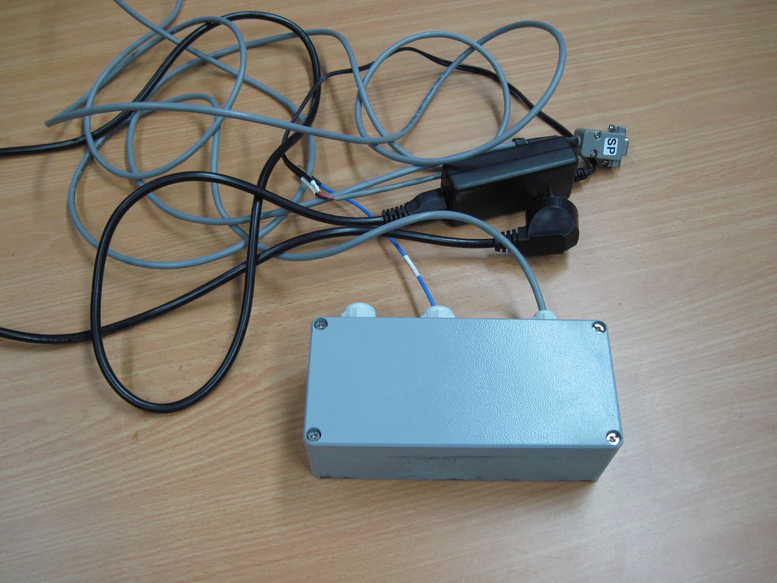
MLLGL3RPT450
Oct 28, 2010TRANSCEIVER 3A
Equipment Class
TNB - Licensed Non-Broadcast Station Transmitter
MLLGL2RPT150
Jan 14, 2006Repeater
Equipment Class
TNB - Licensed Non-Broadcast Station Transmitter
MLLGLXPT2
Sep 16, 2005Wireless Data Collection Transmitter
Equipment Class
TNB - Licensed Non-Broadcast Station Transmitter
MLLGL2RPT450
Jan 23, 2005Repeater
Equipment Class
TNB - Licensed Non-Broadcast Station Transmitter
MLLIWCTX15-17
Dec 21, 2004Field Station
Equipment Class
TNB - Licensed Non-Broadcast Station Transmitter