MLLSPEEDHPTX450Licensed Non-Broadcast Transmitter
Miltel Communications Ltd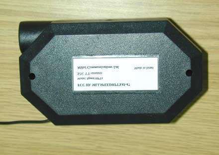
Click to zoom
Application Details
- Equipment Class
- TNB - Licensed Non-Broadcast Station Transmitter
- Date of Grant
- Apr 24, 2002
- Application Purpose
- Original Equipment
- Date of Application
- Apr 24, 2002
- Equipment Note
- Licensed Non-Broadcast Transmitter
- Frequency Range
- 450.00000000 - 470.00000000
- Company
- Miltel Communications Ltd
- Country
- Israel
Documents & Files
Document Text
Text extracted from the exhibit documents filed with the FCC. Open a document above to read the original.
Users Manual
Speed HPTx Wireless Data Link for Meter Reading FCC ID: MLLSPEEDHPTX450 User Manual Miltel Communications Ltd. March 2002 Table of Contents Chapter 1 Introduction................................................................................................. 4 1.1 Purpose and Use............................................................................................ 4 1.2 System General Description ........................................................................... 4 Chapter 2 Theory of Operation ....................................................................................... 5 2.1 General Description ........................................................................................ 5 2.2 Block Diagram Description ............................................................................. 7 2.2.1 General........................................................................................................... 7 2.2.1 Digital Section................................................................................................. 8 2.2.3 RF Section...................................................................................................... 9 Chapter 3 Technical Characteristics ............................................................................. 10 3.1 Technical Specification................................................................................. 10 3.1.1 Electrical ....................................................................................................... 10 3.1.2 Physical ........................................................................................................ 10 3.2 Label Contents ............................................................................................. 11 Chapter 4 Installation Instructions................................................................................. 12 4.1 General......................................................................................................... 12 4.2 Installation .................................................................................................... 12 Chapter 1 Introduction 1.1 Purpose and Use The Speed HPTx ( FCC ID: MLLSPEEDHPTX450 ) is a data link transmitter that is used for data acquisition in Miltel’s utility consumption readings collection system. This device is installed on-site by a professional field technician, thus it includes technical terms. The equipment is not to be installed by a non-professional individual that has not been trained and authorized. 1.2 System General Description The Speed HPTx system is a computerized fully automatic radio device. It requires no human intervention after initial installation. The system enables remote, continuous and accurate reading of water or gas consumption. The Speed HPTx transmits the data acquired from water meters to a receiver connected to a regional concentrator. The concentrator transfers the data to the central computer for data collection and for further analysis and reporting. Chapter 2 Theory of Operation 2.1 General Description The Speed HPTx is the first link in the meter readings data collection system. It is an independent unit that does not require an external power source, wiring, or the preparation of an infrastructure. The unit is installed in proximity to the meters and can be connected to several adjacent meters. Figure 2-1 (see next page) shows a typical installation of a Speed HPTx unit, connected to several water meters (of various types) at a single location. The unit can be connected to any type of meter which has a pulsed output (a passive magnetic open/short reed relay), an active pulse or an encoded output. The Speed HPTx acquires the consumption data from the water meters and stores this data in its memory. The unit includes a miniature RF transmitter which transmits data on a periodic basis to a regional concentrator. Figure 2-1: Speed HPTx Typical Installation 2.2 Block Diagram Description 2.2.1 General Figure 2-2 describes the block diagram of the Speed HPTx unit. This device consists of two major sections, all using a common power source: ! Digital section (Micro Controller) ! RF section Transmitter (Speed Clamp A 3.6 volts Lithium battery provides power to all parts of the device. The power supply for the RF section is controlled via the Tx switch (not shown), thus cutting of power to the transmitter unless necessary for actual data transmission (standby mode). Figure 2-2: Speed HPTx Block Diagram Meter 1 Meter n Sensing and Support Circuitry Micro- Controller RF Transmitter Antenna Battery Device Enclosure Magnetic Switch Tamper Switch 2.2.2 Digital Section The digital section of the Speed HPTx performs the following functions: ! Samples reed switches to detect short/open from each meter. ! Accumulates number of pulses for each meter separately ! Stores data (including battery and tamper alarms) and stores information internal memory ! Interfaces the data to the RF section The digital section is based on a central controller which accepts the following inputs: a. Analog inputs (from reed-relay contacts) designated INPUT1 through INPUTn, each indicating the advance of a single water meter. Alternatively, the Speed HPTx interfaces to an encoded meter. These are the only inputs of the controller. b. Magnetic switch input is utilized only for testing. c. The TAMPER SWITCH input is connected to a micro- switch that senses an opening of the unit's box. This enables the Speed HPTx to generate and transmit an alarm signal in the event of unauthorized opening of the unit casing. d. The LOW VOLTAGE input of the controller is connected to battery via a Low Voltage Detector in order to sense and generate a low battery alarm. Each of the external analog inputs to the controller advances a separate counter in singular steps. The counters in the controller are not pre-settable or resettable to avoid unauthorized tampering (counter matching is thus perform…
Text truncated - open the document above for the full version.
Cover Letter(s)
Miltel Communications Ltd. 7 Leshem Street, 4 th Floor P.O. Box 7374 Petach Tikva, Israel 49170 Tel: 972-3-926-9550 Fax: 972-3-924-6550 11 April 2002 Federal Communications Commission Authorization and Evaluation Division Re: Miltel Communications, FCC ID: MLLSPEEDHPTX450, Ref #316IC2 Confidentiality Request Pursuant to sections 0.457 and 0.459 of the Commission’s rules, the Applicant hereby requests confidential treatment of information accompanying this Application as outlined below: Schematics Block Diagrams Operational Descriptions The above materials contain trade secrets and proprietary information not customarily released to the public. The public disclosure of these matters might be harmful to the Applicant and provide unjustified benefits to its competitors. The Applicant understands that pursuant to Rule 0.457, disclosure of the Application and all accompanying documentation will not be made before the date of the Grant for this Application. Sincerely, Jack Graudenz Chairman
External Photos
FCC ID:MLLSPEEDHPTX450 Page 1 of 3 EXTERNAL PHOTOGRAPHS This document contains 2 photographs FCC ID:MLLSPEEDHPTX450 Page 2 of 3 Photograph No.1 SPEED HPTx (450-470 MHz) front view FCC ID:MLLSPEEDHPTX450 Page 3 of 3 Photograph No.2 SPEED HPTx (450-470 MHz) rear view FCC ID: MLLSPEEDHPTX450 Model: Speed HPTx S/N: YY-nnnnnn Miltel Communications Ltd. Made in Israel
ID Label/Location Info
Speed HPTx ID Label 1 ID Label The equipment label shown below is affixed to the Transmitter device on the bottom panel as depicted in the photos (see attached file – External_Photos Tx). FCC ID: MLLSPEEDHPTX450 Model: Speed HPTx S/N: YY-nnnnnn Miltel Communications Ltd. Made in Israel Label Dimensions: 60 mm. x 25 mm.
ID Label/Location Info
FCC ID:MLLSPEEDHPTX450 Page 3 of 3 Photograph No.2 SPEED HPTx (450-470 MHz) rear view FCC ID: MLLSPEEDHPTX450 Model: Speed HPTx S/N: YY-nnnnnn Miltel Communications Ltd. Made in Israel
Internal Photos
FCC ID:MLLSPEEDHPTX450 Page 1 of 3 INTERNAL PHOTOGRAPHS This document contains 2 photographs FCC ID:MLLSPEEDHPTX450 Revised Photograph No. 1 SPEED HPTx (450-470 MHz) internal view (without battery) FCC ID:MLLSPEEDHPTX450 Page 2 of 3 Photograph No.1 SPEED HPTx (450-470 MHz) internal view (without battery) FCC ID:MLLSPEEDHPTX450 Page 3 of 3 Photograph No.2 SPEED HPTx (450-470 MHz) PCB rear view
Parts List/Tune Up Info
Tune-Up Information The transmitter device has only one trimmer (see C7 in RF section of transmitter schematics) for adjusting and tuning the output frequency. All the other parameters (power, modulation bandwidth and timing) are pre-set to a fixed value and are not changeable or adjustable. The alignment procedure involves a setup that includes a synthesized spectrum analyzer. The output signal is monitored on the spectrum analyzer with a scan-width of 20 KHz. The center of the modulated output waveform is adjusted to within +/- 2 KHz. of the center frequency. This adjustment procedure is performed on the finished and complete unit as a final test before cover closure (after cover closure the transmitter parameters are verified again). This testing procedure is done while the transmitter antenna is brought to the proximity of a wire antenna connected to the spectrum analyzer.
RF Exposure Info
FCC ID:MLLSPEEDHPTX450 Transmitter, model Speed HPTx Exposure limit according to part 1, §1.1310 Limit for power density for general population/uncontrolled exposure is 1 mW/cm 2 . The power density P (mW/cm 2 ) = f/1500 (mW/cm 2 ) = 0.3 mW/cm 2 = P T / 4π r 2 , where P T - the transmitted power, which is equal to the transmitter output. Maximal P T = 17.78 dBm ≈ 60 mW . 0.3 (mW/cm 2 ) = 60 mW / 4π r 2 The minimum allowed distance “r”, where RF exposure limits may not be exceeded, is 4 cm. r = sqrt ( P T / 4π) = sqrt(60/ 0.3 x 4 x 3.14) = 4 (cm). The public cannot be exposed to dangerous RF level.
Test Report
Test Report Date: April, 2002 FCC ID:MLLSPEEDHPTX450 Page 1 of 70 ELECTROMAGNETIC EMISSIONS TEST REPORT ACCORDING TO FCC CFR 47 PART 15 SUBPART B, PART 90 SUBPART I for Miltel Communications Ltd. EQUIPMENT UNDER TEST: Transmitter of automatic meter reading system, model Speed HPTx FCC ID: MLLSPEEDHPTX450 Test Report Date: April, 2002 FCC ID:MLLSPEEDHPTX450 Page 2 of 70 Description of equipment under test Test items Transmitter of automatic meter reading system Manufacturer Miltel Communications Ltd. Types (Models) Speed HPTx Receipt date April 4, 2002 Applicant information Applicant’s representative Mr. Erez Sharabi, V.P. engineering Applicant’s responsible person Mr. Yarum Locker, C.E.O. Company Miltel Communications Ltd. Address 7 Leshem street P.O.Box 7374 Postal code 49170 City Petach Tikva Country Israel Telephone number +972 3926 9550 Telefax number +972 3924 6550 Test performance Test started April 4, 2002 Test completed April 11, 2002 Purpose of test The EUT certfiication in accordance with CFR 47, part 2, §2.1033; part 90 subpart I Test specification(s) FCC part 90 subpart I, §§90.205, 90.209, 90.210, 90.213; part 15 subpart B §15.109 Test Location: Hermon Laboratories Ltd. Certified Test Facilities Test Report Date: April, 2002 FCC ID:MLLSPEEDHPTX450 Page 3 of 70 Contents 1 Summary and signatures ..................................................................4 2 General information ...........................................................................5 2.1 Abbreviations and acronyms ................................................................5 2.2 Specification references .......................................................................5 2.3 EUT description....................................................................................6 3 Test Facility Description....................................................................7 4 Emissions measurements .................................................................8 4.1 Effective radiated power measurements according to FCC part 90 paragraph 205(g) .................................................................................8 4.2 Occupied bandwidth measurements according to FCC part 90 paragraph 209....................................................................................14 4.3 Emission mask according to FCC part 90 paragraph 210(c)..............18 4.4 Frequency stability measurements according to FCC part 90 paragraph 213....................................................................................55 4.5 Radiated emission measurements according to FCC part 15 subpart B §15.109...........................................................................................62 4.6 Transient Frequency Behavior according to FCC part 90 Paragraph 214 .....................................................................................................65 APPENDIX A - Test equipment and ancillaries used for tests ................69 APPENDIX B-Test equipment correction factors .....................................70 Test Report Date: April, 2002 FCC ID:MLLSPEEDHPTX450 Page 4 of 70 1 Summary and signatures The EUT, Speed HPTx transmitter of automatic meter reading system, was tested according to FCC part 90 subpart I, §§90.205, 90.209, 90.210, 90.213, part 15 subpart B §15.109 and found to comply with the standard requirements. Test description Specification reference Test report paragraph Pass / Fail RF output power 90.205, 2.1046 4.1 Pass Occupied bandwidth 90.209 2.1049 4.2 Pass Emission mask 90.210 4.3 Pass Radiated spurious emissions 90.210 2.1053 4.3 Pass Frequency stability vs temperature 90.213 2.1055 4.4 Pass Frequency stability vs voltage 2.1055 4.4 Pass Radiated emissions 15.109 4.5 Pass Test Report Date: April, 2002 FCC ID:MLLSPEEDHPTX450 Page 5 of 70 2 General information 2.1 Abbreviations and acronyms The following abbreviations and acronyms are applicable to this test report: cm centimeter dB decibel dBm decibel referred to one milliwatt dB(μV) decibel referred to one microvolt dB(μV/m) decibel referred to one microvolt per meter DC direct current EMC electromagnetic compatibility EUT equipment under test GHz gigahertz H height Hz hertz kHz kilohertz kV kilovolt L length m meter MHz megahertz MW milliwatt NA not applicable PC personal computer QP quasi-peak (detector) RE radiated emission rms root-mean-square sec second V volt VCO volt control oscillator W watt 2.2 Specification references CFR 47 part 15: 10/2001 Radio Frequency Devices CFR 47 part 90: 10/2001 Private land mobile radio services, Subpart I ANSI C63.2:06/1996 American National Standard for Instrumentation- Electromagnetic Noise and Field Strength, 10 kHz to 40 GHz-Specifications. ANSI C63.4:1992 American National Standard for Methods of Measurement of Radio-Noise Emissions from Low- Voltage Electrical and Electronic Equipment in the Range of 9 kHz to 40 GHz. Test Report Date: April, 2002 FCC ID:MLLSPEEDHPTX450 Page 6 of 70 2.3 EUT description The EUT, Speed HPTx, is a data link transmitter operating in 450 –470 MHz frequency range and used for data acquisition in Miltel’s water consumption readings collection system. The automatic meter reading system is a fully computerized radio device. It requires no human intervention after initial installation. The system enables remote, continuous and accurate reading of water consumption. The Speed HPTx transmits the data acquired from water meters to a regional concentrator. The concentrator transfers the data to the central computer for data collection and for further analysis and reporting. The transmitter is powered by an internal 3.6 V lithium battery and can be connected to several meters (e.g. water) in parallel. The transmitter is enclosed in a plastic enclosure. An integral wire antenna soldered to the internal Printed Circuit Board is used. Test Report Date: April, 2002 FCC ID:MLLSPEEDHPTX450 Page 7 of 70 3 Test Facility Description Tests were performed at Hermon Lab…
Text truncated - open the document above for the full version.
Test Report
Test Report Date: April, 2002 FCC ID:MLLSPEEDHPTX450 4.6 Transient Frequency Behavior according to FCC part 90 Paragraph 214 4.6.1 General This test was performed to determine the maximum frequency difference limits during the time intervals as defined in part 90 paragraph 214. 4.6.2 Test Procedure The transmitter was tested for transient frequency behavior using the test methodology defined in TIA/EIA-603-A (2.2.19.3). The test set up is depicted below in Figure 4.6.1. The functions of the RF power meter and the test receiver were performed by a Marconi FM Detector (HL793). The scope (HL 670) was triggered by a signal from the transmitter. Figure 4.6.1 Transient Frequency Behavior Test Set Up The test results as per 90.214 are recorded in Table 4.6.1 and shown in Plots 4.6.1 – 4.6.2. Table 4.6.1 Transient Frequency Measurements Time Intervals Maximum Frequency Difference KHz. Pass / Fail t 1 = 10 msec. ±12.5* Pass t 2 = 25 msec. ±6.25* Pass During the time from the end of t 2 to the beginning of t 3 the frequency difference must not exceed the limit specified in 90.213 (±2.5 PPM x 460 MHz. = ±1.15 KHz.) Pass t 3 = 10 msec. ±12.5* Pass * The frequency difference during this time period may exceed the defined maximum frequency difference because the transmitter carrier output power rating is less than 6 watts TRANSMITTER UNDER TEST RF SIGNAL GENERATOR HL 1882 COMBINING NETWORK HL 1907 RF POWER METER TEST RECEIVER FM DETECTOR HL 793 STORAGE OSCILLOSCOPE HL 670 RF DETECTOR HL 101 DIRECTIONAL COUPLER Test Report Date: April, 2002 FCC ID:MLLSPEEDHPTX450 Reference numbers of test equipment used HL 670 HL 1907 HL 101 HL 793 HL 1882 Full description is in Appendix A. Plot 4.6.1 Turn On test results Date/Time: April 22 2002 11:57:01 AM Test Name: Turn On Customer: Miltel EUT: Speed HPTx t on t 1 t 2 Test Report Date: April, 2002 FCC ID:MLLSPEEDHPTX450 Plot 4.6.2 Turn Off test results Date/Time: April 22 2002 12:08:25 PM Test Name: Turn Off Customer: Miltel EUT: Speed HPTx t 3 t off Test Report Date: April, 2002 FCC ID:MLLSPEEDHPTX450 Transient Frequency Behavior Test Set Up Test Report Date: April, 2002 FCC ID:MLLSPEEDHPTX450 APPENDIX A - Test equipment and ancillaries used for tests Manufacturer information No. Description Name Model No. Serial No. Due calibr. 0041 Double ridged guide antenna, 1-18 GHz Electro-Metrics RGA 50/60 2811 3/03 0101 Detector crystal, 0.01 – 12.4 GHz Hewlett Packard 420A 101 11/02 Check 0446 Active Loop Antenna 10 kHz-30 MHz Electro- Mechanics 6502 2857 10/02 0465 Anechoic Chamber 9 (L) x 6.5 (W) x 5.5 (H) m HL AC-1 023 3/03 0493 Oven temperature Thermotron S-1.2 Mini- Max 4016 9/02 0521 Spectrum Analyzer with RF filter section (EMI Receiver 9 kHz - 6.5 GHz) Hewlett Packard 8546A 0319 9/02 0558 Multimeter Digital Fluke 76 0904 10/02 0589 Cable Coaxial, A2POL118.2, 3m GORE GORE-3 589 12/02 0591 Attenuator 10 dB, 50 Ohm, N-type, 2W Elisra Electronic Systems MW2100-N- Type 3 1/03 0604 Antenna Biconilog Log-Periodic/T Bow-Tie, 26 - 2000 MHz EMCO 3141 9611-1011 1/03 0614 Antenna Dipole Tunable 200 – 1000 MHz Electro-Metrics TDS 30-1/30-2 334 1/03 0661 Generator Swept Signal, 10 MHz to 40GHz+ 10dBm Hewlett Packard 83640B 0266 9/02 0670 Oscilloscope, Digital storage 500MHz, 2Gs/s, 4ch with Telecom Mask Tester LeCroy Corporation LC 334A+MT01/0 2 2387 8/02 0758 Power supply, 36 V, 1 A Horizon Electronics DHR 36-1 5361231 6/02 Check 0793 Radio communication test set Marconi Instruments 2955 9507/179 2/03 0808 Analyzer spectrum, 100 Hz to 2.2 GHz, AM/FM modulator Anritsu MS2601B M178731 3/03 1004 Cable coaxial, PSWJ4, 6 m ANDREW ANDREW-6 163 12/02 1424 Spectrum analyzer, 30 Hz - 40 GHz Agilent Technologies 8564EC 3946A00219 8/02 1425 EMI Receiver System, 9 kHz - 2.9 GHz Agilent Technologies 8542E 3710A00222 9/02 1536 Cable RF, 2 m Alpha Wire RG-58C/U NA 9/02 1620 Attenuator, 50 Ohm, 2 W, DC to 8 GHz, 10 dB Midwest Microwave 0217-10-NNN- 02 NA 1/03 1882 Generator signal, 0.1 – 990 MHz Hewlett Packard 8656A 2228A03615 9/02 1907 Power splitter/combiner, 5-500 MHz Mini-Circuits ZFSCC-2-1 NA 7/02 1940 Cable 40 GHz, 1.5 m, blue Rhophase Microwave Ltd. KPS-1503A- 1500-KPS T4663 10/02 1947 Cable 18 GHz, 6.5 m, blue Rhophase Microwave Ltd NPS-1803A- 6500-NPS T4974 10/02
Test Report
/04/200 Emmission Designator Calculation M – Modulation frequencies are: 0.9 KHz. and 2.4 KHz. R65 22K 1 2 R64 1M R63 10k D4 LM4041EIM3X-1.2 2 1 3C36 N.U DATA In To vco V D4 x R65 V max = (R64+R65) 1.2Vx 3.3K V max = (1M+3.3K) = 0.004 For every 1Volt the frequency deviation is 124K Using the formula B(n) = 2M + 2DK Where: M = 2.4 DK = 124 X 0.004 = .496 BW -3dB max = ( 2 x 2.4 ) + ( 2 x 0.496 ) = 5.8 KHz. Therefore the emmission designator should be 5K8F1D 3.3K
Contact Information
Applicant
Yarum Locker(General Manager)
Test Firm
Hermon Laboratories Ltd.Alexander Usoskin
Technical Specifications
| # | Rule Parts | Frequency Range | Power Output | Emission | Tolerance |
|---|---|---|---|---|---|
| 1 | 90 | 450 MHz - 470 MHz | 60.00 mW | 5K8F1D | 2.5000000000 ppm |
Other Applications from Miltel Communications Ltd
MLLGL3RPT450
Oct 28, 2010TRANSCEIVER 3A
Equipment Class
TNB - Licensed Non-Broadcast Station Transmitter
MLLGL2RPT150
Jan 14, 2006Repeater
Equipment Class
TNB - Licensed Non-Broadcast Station Transmitter
MLLGLXPT2
Sep 16, 2005Wireless Data Collection Transmitter
Equipment Class
TNB - Licensed Non-Broadcast Station Transmitter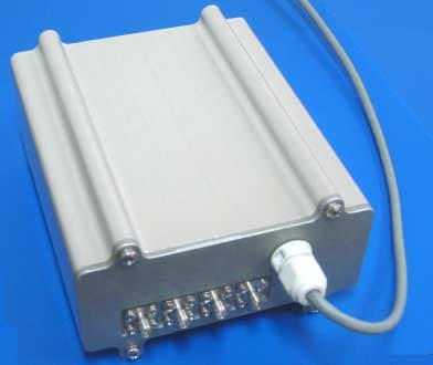
MLLGL2RPT450
Jan 23, 2005Repeater
Equipment Class
TNB - Licensed Non-Broadcast Station Transmitter
MLLIWCTX15-17
Dec 21, 2004Field Station
Equipment Class
TNB - Licensed Non-Broadcast Station Transmitter