MLLSPEEDTRD433L1Low Power Meter Reading Transceiver
Miltel Communications Ltd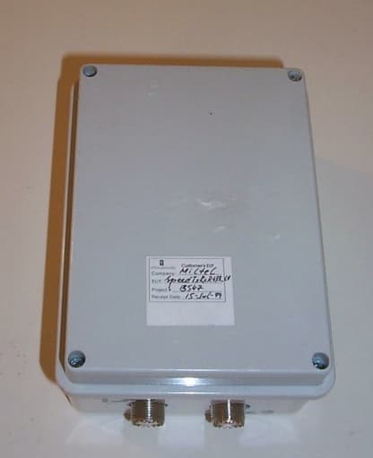
Click to zoom
Application Details
- Equipment Class
- DSC - Part 15 Security/Remote Control Transmitter
- Date of Grant
- Oct 20, 1999
- Application Purpose
- Original Equipment
- Date of Application
- Jul 24, 1999
- Equipment Note
- Low Power Meter Reading Transceiver
- Frequency Range
- 433.92000000 - 433.92000000
- Company
- Miltel Communications Ltd
- Country
- Israel
Documents & Files
Document Text
Text extracted from the exhibit documents filed with the FCC. Open a document above to read the original.
Users Manual
Speed TxRx Miltel Communications Ltd.1 Speed TxRx Tranceiver FCC ID - SPEEDTRD433L1 User Manual Miltel Communications Ltd. June 1998 Speed TxRx User Manual Miltel Communications Ltd.2 Table of Contents Chapter 1 Introduction...................................................................................................3 1.1 Purpose and Use ............................................................................................3 1.2 System General Description ...........................................................................3 Chapter 2 Theory of Operation .....................................................................................5 2.1 General Description ........................................................................................5 2.2 Block Diagram Description..............................................................................5 Chapter 3 Technical Characteristics ............................................................................9 3.1 Technical Specification ...................................................................................9 3.1.1 Electrical .........................................................................................................9 3.1.2 Physical.........................................................................................................10 3.2 Label Contents..............................................................................................11 Chapter 4 Installation Instructions .............................................................................13 4.1 General .........................................................................................................13 4.2 Installation.....................................................................................................10 Speed TxRx User Manual Miltel Communications Ltd.3 Chapter 1 Introduction 1.1 Purpose and Use The Speed TxRx Transceiver (FCC ID - SPEEDTRD433L1) is a low-power data link transceiver that relays digital data from low power Transmitters (FCC ID - MLLTX433L1 ), which are connected to water meters, to a Regional Concentrator. It is also used in the receive mode as a front-end to the Concentrator. The information in this manual is provided only as instructions for installation and does not entitle user to make any modifications or adjustments. 1.2 System General Description The Speed TxRx system is a computerized fully automatic radio device. It requires no human intervention after initial installation. The device includes the following parts: 1. Transmitter 2. Receiver 3. Controller 4. Antennas and cables 5. DC regulator 6. Enclosure The Transceiver receives DC power and digital data from the Repeater or Concentrator and Transmit \ Receive RF through coaxial cables which are connected to half wavelength Dipole antennas. Note: 1) The system, including transmitters, transceivers and concentrators, is installed and maintained only by qualified professional technicians. 2) The device is not adjustable by user and is supplied by manufacturer ready for installation witout provisions for adjustmant. Speed TxRx Miltel Communications Ltd.5 Chapter 2 Theory of Operation 2.1 General Description In receive mode, the Speed TxRx receives data from the Speed Tx Transmitters which are deployed near the water meter/s or from other Speed TxRx units which are in Transmit mode. The received data is processed differently whether the unit is connected to a Repeater control device or as a front-end to a Concentrator. When connected to a Repeater, the received data is processed in the Repeater’s controller. Only messages, which need to be relayed, are transferred to the Transceiver’s controller. The Controller initiates a transmission only if 30 sec. have elapsed from the previous transmission. Upon validation, the Controller switches the Transceiver to Transmit mode and transmits the data. The controller also selects the antenna from which the message will be transmitted/received. When connected as a Concentrator front-end, the Transceiver operates in receive mode. The received data is transferred to the concentrator for further processing of the meter data. Speed TxRx User Manual Miltel Communications Ltd.6 2.2 Block Diagram Description 2.2.1 General Figure 2-1 describes the block diagram of the Speed Tx Rx unit. RF is received or transmitted from either antennas upon the controller selection. Two antennas are used to improve performance in urban environment where shadowing, due to tall buildings, generates sever multipath effect. This effect can reduce the received signal by more than 30dB, thus by switching antennas periodically the transceiver improves reception. 2.2.2 Transmitter A PLL IC ( MC13176 from Motorola Semiconductors) gets the reference, 13.56MHz, from a crystal oscillator and locks the VCO output, divided by 32, to the crystal frequency. Therefore, the output frequency equals Crystal_frequency x 32 = 433.92 MHz. The message digital data from the Controller is shaped and modulates the VCO frequency. The VCO output is attenuated by a resistive Π Attenuator. A 6 pole low pass filter that rejects the harmonics, further filters the output. The output is routed through a T/R switch and a diversity switch to the output/input UHF connectors. Coaxial cables connect the half-wavelength dipole antennas with the Transceiver. All the emissions parameters are in compliance with FCC part15C specifically the limitations set by 15.231(e). When the Transceiver is in the receive mode the voltages to the Transmitter are off. Speed TxRx User Manual Miltel Communications Ltd. 7 Figure 2-2: Speed TxRx Block Diagram AntennaAntenna VCO Phase Locked LOOP(PLL) MC13176 Crystal 13.56MHz Internal adjustment range 433.92MHz +/- 35KHz 433.92MHz VCO Crystal 13.56MHz Diversity switch T/R switch SAW filter 433.92MHz BPF & LNA 10.7MHZ 1 st IF VCO Crystal 10.245MHz 423.22MHz LO 455KHz 2 nd IF FM Demodulator Coaxial Cables Harmonic Filter …
Text truncated - open the document above for the full version.
Attestation Statements
Attestation Statement 28 July, 1999 Re: MLLSPEEDTRD433L1 1. The manufacturer of the Speed TxRx 433_L1 transceiver (FCC ID: MLLSPEEDTx433L1) hereby declares that the device complies with FCC Part 15C. 2. The equipment has been tested in Hermon Laboratories, a certified lab with fully equipped facilities, as required for the test of intentional radiators. 3. This device complies with new rules adopted under docket 87-389 and is not affected by section 15.37. 4. The equipment tested is a production sample. 5. Operation is subjected to the following two conditions: (1) This device may not cause harmful interference, and (2) this device must accept any interference that may cause undesired operation 6. Contact for inquiries: Technical- David Heller [email protected] Other - Yarum Locker [email protected] Sincerely, Yarum Locker General Manager Miltel Communications Ltd. P.O.Box 138 Moshav Zafaria ISRAEL 60932 Tel. +972-9606105 Fax +972-9606687
Cover Letter(s)
29 July, 1999 Federal Communications Commission Equipment Approval Services Pittsburgh, PA 15251-5351 Re: Application for Certification - MLLSPEEDTRD433L1 731 Confirmation Number: EA94930 Dear Sir: 1. Miltel Communications kindly presents the following documents as attachments to it Form 731 application for FCC certification (MLLSPEEDTRD433L1 – Filed electronically). 2. Form 159 (Remittance Advice) has been sent by mail (e-filing non-active). 3. Miltel Communications hereby requests that technical details and other proprietary information remain confidential as to maintain Miltel Communications’ commercial secrets (The appropriate fee has been paid). To protect Miltel Communications’ intellectual property we kindly request that the following documents will not be released to the public: Block Diagram Electronic Schematics Operational Description Parts List / Tune Up Info 4. This Document is accompanied by the following attachments: Attestation Statement External Photos ID Label / Location Info Internal Photos Block Diagram Operational Description Miltel Communications Ltd. P.O.Box 138 Moshav Zafaria ISRAEL 60932 Tel. +972-9606105 Fax +972-9606687 Parts List / Tune Up Info RF Exposure Info Schematics Test Report Test Setup Photos Users Manual 5. Contact for inquiries: Technical - David Heller [email protected] Other - Yarum Locker [email protected] Sincerely, Yarum Locker General Manager Miltel Communications Ltd. P.O.Box 138 Moshav Zafaria ISRAEL 60932 Tel. +972-9606105 Fax +972-9606687
Cover Letter(s)
29 July, 1999 Federal Communications Commission Equipment Approval Services Pittsburgh, PA 15251-5351 Re: Request for Confidentiality - MLLSPEEDTRD433L1 731 Confirmation Number: EA94930 Dear Sir: 1. Based on the rule sections 0.457 and 0.459, Miltel Communications kindly requests that technical details and other proprietary information remain confidential as to maintain Miltel Communications’ commercial secrets. 2. The appropriate fee has been paid as required. 3. To protect Miltel Communications’ intellectual property we kindly request that the following documents will not be released to the public: Block Diagram Electronic Schematics Internal Photos Operational Description (theory of operation) Parts List / Tune Up Info 4. All of the above information is not available to the end user and it is disclosed at this level of detail only for the sake of FCC certification. 5. Contact for inquiries: Technical - David Heller [email protected] Other - Yarum Locker [email protected] Sincerely, Yarum Locker General Manager Miltel Communications Ltd. P.O.Box 138 Moshav Zafaria ISRAEL 60932 Tel. +972-9606105 Fax +972-9606687
External Photos
External Photos L L a a b b e e l l L L o o c c a a t t i i o o n n
ID Label/Location Info
ID Label The equipment label shown below is affixed to the Transceiver device on the front panel as depicted in the photos (see photo file – TxRx External_Photos). FCC ID: MLLSPEEDTRD433L1 Model: Speed TxRx_433_L1 S/N: YY-nnnnnn Miltel Communications Ltd. Made in Israel This device complies with Part 15 of the FCC rules. Operation is subjected to the following two conditions: (1) This device may not cause harmful interference, and (2) this device must accept any interference that may cause undesired operation. Label Dimensions: 55 mm. x 28 mm. Label Location: Transceiver front panel
Test Report
T T E E S S T T R R E E P P O O R R T T Prepared for: Miltel Communications Ltd. Test of: TxRxD_433_L1 Transceiver FCC ID: MLLSPEEDTRD433L1 To comply with :FCC 1998 subpart 15C - Intentional Radiators Test Facilities: Hermon Laboratories Israel Tested by: David Heller – TetraWave Michael Feldman - Hermon Laboratories Prepared by: David Heller – TetraWave Yarum Locker - Miltel Communications Approved by: Jacob Y. Graudenz Miltel Communications Speed TxRx TransceiverTest Report 1 July 1999 Speed TxRx TransceiverTest Report 2 Table of Contents 1. General Information 2 2. Equipment Under Test (E.U.T.) 3 3. Operation of E.U.T. 4 4. Test Specifications 5 5. Test Procedures 5 6. Deviations from Specifications 5 7. Summary of Test Results 6 8. Measurements Uncertainty 6 9. Measurements Methods and Test Results 7 Appendix 1. List of Test Equipment 10 Appendix 2. Test set-up drawings and pictures 11 Appendix 3. Graphical Test Results 13 Appendix 4. Photographs of E.U.T. 16 Speed TxRx TransceiverTest Report 3 1. General Information 1.1 Company information Company Name: Miltel Communication System Ltd. Address: P.O.Box 138 , Moshav Zafria , ISRAEL Contact Name: Yarum Locker, General Manager 1.2 Location of Tests All the measurements in this report were performed with the calibrated test equipment and at certified test facilities of: Hermon Laboratories Ltd. Rakevet Ind. Zone, P. O. Box 23 Binyamina 30550, ISRAEL Phone: +972 6 6288001 E-mail: [email protected] Fax: +972 (0) 6 6288277 http://www.hermonlabs.com/ Speed TxRx TransceiverTest Report 4 2. Equipment Under Test (E.U.T.) Brand Name Miltel Speed Model SPEED TxRx_433_L1 Unique Type Identification Transceiver Serial Number 99-00163 Country of Manufacture ISRAEL FCC ID Identifier MLLSPEEDTRD433L1 Date of tests 15 July 99 Description of E.U.T. The EUT is a DC operated Transceiver connected to a Concentrator or a Repeater. The EUT includes 2 coaxial cables and 2 dipole antennas and was so tested. When deployed as a minimum with a Transmitter and a Concentrator forms a system. For more details see the Block Diagram attached to form 731. Modifications to E.U.T. None Additional Information Power Supply Requirement: External – 12 V. DC Operating Environment: Residential Weight: 420gr Dimension: 16 x 12 x 7.5 cm. Interface: Shielded 5-wire cable. Support Equipment None Speed TxRx TransceiverTest Report 5 3. Operation of E.U.T. Environmental Test Conditions The E.U.T. was tested at 28 0 C and 58% Humidity. E.U.T. Operating Modes The EUT has two modes: 1. Transmit 2. Receive Although the Transmit mode is by far the worst condition for radiated the Receive mode was also tested for verification as per 15.101(b). E.U.T. Configuration and Peripherals Two Dipole Antennas were connected to the Transceiver with 3 meters RG213 coaxial cables. The EUT was connected to a Concentrator (support equipment) that controlled the operating modes. In Transmit mode test, the software on the Concentrator forced the EUT to transmit consecutive messages in order to measure the emissions with the automatic EMC receiver (spectrum analyzer). Support Equipment DescriptionConcentrator, (Class B Digital Device) Brand NameMiltel Communications Ltd. Model NameCML110-1 Serial Number99-10012 Cable Length and Type3 meter, 5-wire, shielded Connected to PortJ1 on PCB Speed TxRx TransceiverTest Report 6 4. Test Specifications Reference FCC part 15.231(e) and all the other relevant parts of subpart 15C (e.g. 15.205, 15.209) in Transmit mode. FCC part 15.209,109 in Receive mode and all the other relevant parts of part 15. Title CFR (47 part 15) Radio Frequency Devices Comments A description of the test facility (Hermon Laboratories) is on file at the FCC as required by Section 2.948 Purpose of Test Determine E.U.T. compliance with the specifications for the purpose of certification. 5. Methods and Procedures The Method of measurements used for the measurements are detailed in ANSI C63.4 (1992), Title: “American National Standard Methods of Measurement of Electromagnetic Emissions from Low Voltage Electrical and Electronic Equipment in the range of 9KHz to 40GHz”. Other Relevant ANSI standards as delineated in the above document’s chapter 2: References 6. Deviations from Specifications None Speed TxRx TransceiverTest Report 7 7. Test Results Summary MeasurementRange of MeasurementsSpecificationsComply ( Yes / No) Radiated Emissions Fundamental 433.92MHz15.231(e) Yes Radiated Emissions Spurious (Transmit and Receive) 30MHz to 4.5GHz15.231(e),15.205, 15.209, 15.109 Yes Bandwidth (Fundamental) 433.92MHz15.231(c) Yes Transmit Duration and Duty Cycle 433.92MHz15.231(e) Yes 8. Measurement Uncertainty Speed TxRx TransceiverTest Report 8 9. Measurement Methods and Test Results 9.1 Radiated Emission Measurement Results Measurement Method The tests were performed in Hermon Labs large (9m X 6.5m X 5.5m) full Anechoic Chamber with conductive floor (see attached drawing). The EUT was placed on a wooden turntable with the Dipole antennas and the coaxial cables. The Concentrator, which controlled the EUT via the 5-wire shielded cable, was also placed on the turntable. The Concentrator operated during all the tests. The Hydraulic antenna tower was moved such that the receive antenna was 3 meters from the EUT. The frequency range from 30MHz to 4.5GHz was investigated using an automatic HP8546A EMI receiver 9KHz –6.5GHz and HP85460A RF filter section. The receive antenna height was changed from 1to 4 meters, polarization was changed from Vertical to Horizontal and the turntable was rotated 360 0 . The following table lists frequencies at which emissions were measured using an average detector (as per 2.231(b)(2)). Limits Limit for fundamental was used as per 15.231(e): 4400μμV/m or 72.8dB μV/m. Limits for spurious emissions were used as per 15.209 for restricted bands. For the other bands, 15.231(e) or 15.209 which ever is higher as per 15.231(b)(3). In the transmit mode, the EUT was operating in the test mode…
Text truncated - open the document above for the full version.
Test Report
Speed TxRx TransceiverTest Report Appendixes Appendix 1 - List of Test Equipment EquipmentManufacturerModel EMC ReceiverHPHP8546A+HP85460A ControllerANRL2-SR3000 Biconilog AntennaEMMCO3141 Ridged Horn Antenna 1-18GHzElectro-MetricsRGA50/60 Spectrum AnalyzerAnritsuMS2601A Equipment Calibration All the above listed test equipment at Hermon Laboratories, including additional accessories (Cables, Attenuators and Adapters), have been calibrated according to their recommended procedure and is within the manufacturer’s specified limits of error. The Laboratory equipment is calibrated by a third party (Traceable to NIST, USA), on a regular basis and according to equipment manufacturer specifications. Speed TxRx Transceiver Test Report Appendixes Appendix 2 - Test Setup Drawings and Pictures Test Chamber 3 meter Antenna Mast & Turntable Control Test Receiver 1-4 meter Control EUT (Transceiver) Concentrator (Support Equipment) EUT Antennas Note: Setup Pictures in separate files Speed TxRx TransceiverTest Report Appendixes Appendix 3. Graphical Test Results Radiated Emissions Bandwidth Appendix 4 - Photographs of EUT See pictures of Speed TxRx Transceiver in attached files.
Test Setup Photos
Transceiver Test Setup In the below picture a horn antenna was used for 1-4.5 GHz. For 30-1000 MHz. a biconilog antenna was used (see page 2 in next file). EUT’s Antennas Concentrator Transceiver (EUT) Turntable Page 2-3 saved in separate files: TxRx Setup_Photos_2 TxRx Setup_Photos_3
Test Setup Photos
Page 2 of 3 Transceiver Test Setup Close-Ups The Transceiver was tested while connected to the Concentrator (support equipment). The worst case radiated emission of the two units was recorded.
Test Setup Photos
Speed TxRx - Test Setup Page 3 of 3 Chamber Control Setup Monitor Controller EMC Receiver
Contact Information
Applicant
Yarum Locker(General Manager)
Technical Contact
Non-Technical Contact
Miltel Communications Ltd.Yarum Locker
[email protected]+972-3-9269545
Test Firm
Hermon Laboratories Ltd.Alexander Usoskin
Technical Specifications
| # | Rule Parts | Frequency Range | Power Output |
|---|---|---|---|
| 1 | 15C | 433.92 MHz - 433.92 MHz | - |
Other Applications from Miltel Communications Ltd
MLLGL3RPT450
Oct 28, 2010TRANSCEIVER 3A
Equipment Class
TNB - Licensed Non-Broadcast Station Transmitter
MLLGL2RPT150
Jan 14, 2006Repeater
Equipment Class
TNB - Licensed Non-Broadcast Station Transmitter
MLLGLXPT2
Sep 16, 2005Wireless Data Collection Transmitter
Equipment Class
TNB - Licensed Non-Broadcast Station Transmitter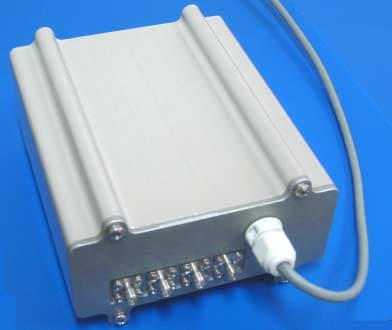
MLLGL2RPT450
Jan 23, 2005Repeater
Equipment Class
TNB - Licensed Non-Broadcast Station Transmitter
MLLIWCTX15-17
Dec 21, 2004Field Station
Equipment Class
TNB - Licensed Non-Broadcast Station Transmitter