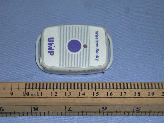
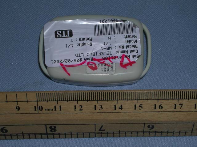
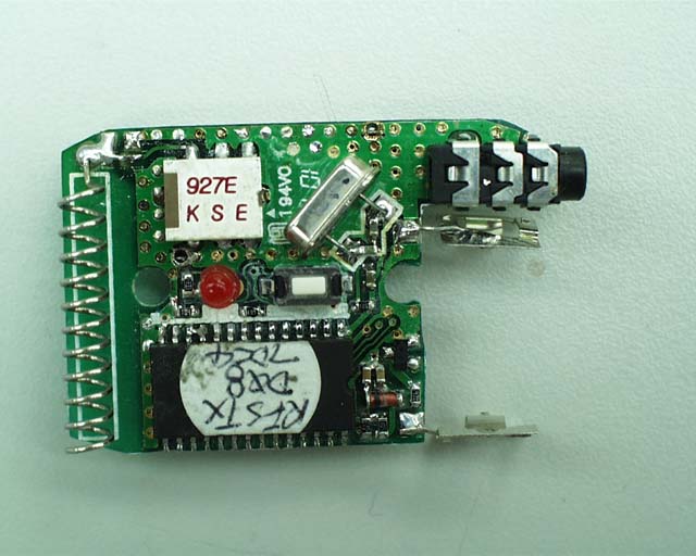
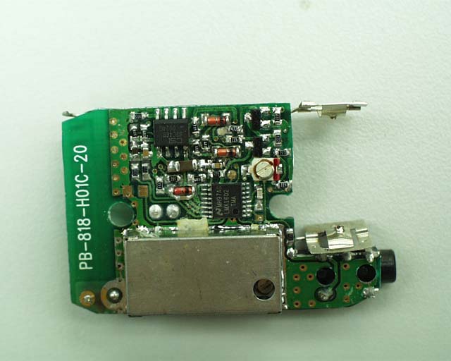
MZVWP-1Emergency Alarm Pendant
Telefield Ltd.
Click to zoom
Application Details
- Equipment Class
- DXX - Part 15 Low Power Communication Device Transmitter
- Date of Grant
- Mar 19, 2001
- Application Purpose
- Original Equipment
- Date of Application
- Mar 05, 2001
- Equipment Note
- Emergency Alarm Pendant
- Frequency Range
- 924.87500000 - 927.72500000
- Company
- Telefield Ltd.
- Country
- Hong Kong
Documents & Files
Document Text
Text extracted from the exhibit documents filed with the FCC. Open a document above to read the original.
Users Manual
Operation: Installation The Pendant operates on three 1.5V batteries. The lift of those batteries for standby is approximately 3 years. There are two screws on the back of the transmitter that hold the top and bottom case together. Recommendation: Test your transmitter periodically to ensure that all the batteries are working. If the communication distance or the brightness of alarm LED reduced, please replace all batteries with new one. To replace the Pendant batteries: 1. Undo the two screws on the back of the transmitter. The bottom case will then come off. 2. Take out all the old batteries using a small screwdriver or a pen 3. Place the new batteries in position. 4. Reprogram the device if necessary. 5. Close the battery cover and reinsert two screws. Programming Pendant allows you to activate WR-1 or WR-2 receivers after programming shown below. 1. Press and hold the “SETUP” button of the Receiver unit until the “SETUP” LED lights up. 2. Press the “ALARM” button of Pendant once, the alarm LED will light up (or flash slowly for first setup). 3.Plug the program cable to Base unit and Pendant, LED will quickly flash to indicate connection successfully. 4.Select one of 16 locations in sequence by pressing “SETUP” button (for WR-1, WR-2). 5. Press and hold “SETUP CONFIRM” button to assure. The “SETUP” LED on Base unit will turn off and “ALARM” LED on transmitter will turn off once if installation successfully. 6. Disconnect the program cable; alarm LED of Pendant turn off. 7. Press the “ALARM” button of Pendant once, the corresponded unit LED on Base unit will light up and alarm will hear. 8. Repeat step 2~7 for other Transmitters. Operation In an emergency, you can activate the WR-1 or WR-2 receivers using the Pendant. Press the “ALARM” button once will transmit alarm to receiver for around 2.5 minutes to activate the receivers. To release the alarm on receiver, press the “ALARM RESET” button on the receiver to turn off the alarm sound and corresponded unit LED. FCC Warning Changes or modifications to this unit not expressly approved by the party responsible for compliance could void the user’s authority to operate the equipment. NOTE: This equipment has been tested and found to comply with the limits for a Class B digital device, pursuant to Part 15 of FCC Rules. These limits are designed to provide reasonable protection against harmful interference in a residential installation. This equipment generates, uses and can radiate radio frequency energy and, if not installed and used in accordance with the instructions, may cause harmful interference to radio communication. However, there is no guarantee that interference will not occur in a particular installation. If this equipment does cause harmful interference to radio or television reception which can be determined by turning the equipment off and on, the user in encouraged to try to correct the interference by one or more of the following measures. ® Reorient or relocate the receiving antenna. ® Increase the separation between the equipment and receiver. ® Connect the equipment into an outlet on a circuit different from that to which the receiver is connected. ® Consult the dealer or an experienced radio/TV technician for help.
Test Report
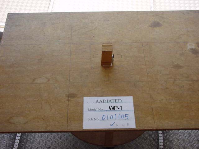
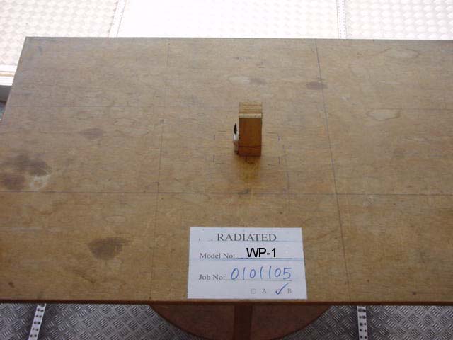
Telefield Limited Application For Certification (FCC ID: MZVWP-1) Transmitter WO# 0101105 WL/Roy February 27, 2001 INTERTEK TESTING SERVICES FCC ID: MZVWP-1 i LIST OF EXHIBITS INTRODUCTION EXHIBIT 1 :General Description EXHIBIT 2 :System Test Configuration EXHIBIT 3 :Emission Results EXHIBIT 4 :Equipment Photographs EXHIBIT 5 :Product Labelling EXHIBIT 6 :Technical Specifications EXHIBIT 7 :Instruction Manual EXHIBIT 8 :Miscellaneous Information INTERTEK TESTING SERVICES FCC ID: MZVWP-1 ii MEASUREMENT/TECHNICAL REPORT Telefield Limited - MODEL: UMP Wireless Sentry WP-1 FCC ID: MZVWP-1 February 27, 2001 This report concerns (check one:)Original Grant X Class II Change Equipment Type: Low Power Transmitter (example: computer, printer, modem, etc.) Deferred grant requested per 47 CFR 0.457(d)(1)(ii)?Yes No X If yes, defer until: date Company Name agrees to notify the Commission by: date of the intended date of announcement of the product so that the grant can be issued on that date. Transition Rules Request per 15.37?Yes No X If no, assumed Part 15, Subpart C for intentional radiator - the new 47 CFR [10-1-96 Edition] provision. Report prepared by:Wilson Loke Intertek Testing Services 2/F., Garment Center, 576, Castle Peak Road, HONG KONG Phone: 852-2173-8575 Fax:852-2745-8306 INTERTEK TESTING SERVICES FCC ID: MZVWP-1 iii Table of Contents 1.0 General Description................................................................................................................ 2 1.1 Product Description ............................................................................................................... 2 1.2 Test Methodology .................................................................................................................. 3 1.3 Test Facility............................................................................................................................ 3 2.0 System Test Configuration...................................................................................................... 5 2.1 Justification ............................................................................................................................ 5 2.2 EUT Exercising Software ....................................................................................................... 5 2.3 Special Accessories ................................................................................................................ 5 2.4 Equipment Modification ........................................................................................................ 6 2.5 Support Equipment List and Description ............................................................................... 6 3.0 Emission Results...................................................................................................................... 8 3.1 Field Strength Calculation ...................................................................................................... 9 3.2 Radiated Emission Configuration Photograph ..................................................................... 11 3.3 Radiated Emission Data ....................................................................................................... 12 4.0 Equipment Photographs....................................................................................................... 15 5.0 Product Labelling.................................................................................................................. 17 6.0 Technical Specifications........................................................................................................ 19 7.0 Instruction Manual................................................................................................................ 21 8.0 Miscellaneous Information................................................................................................... 23 8.1 Discussion of Pulse Desensitization ..................................................................................... 24 8.2 Calculation of Average Factor ............................................................................................. 25 8.3 Emissions Test Procedures...................................................................................................26 8.4 Bandedge Plot ...................................................................................................................... 28 INTERTEK TESTING SERVICES FCC ID: MZVWP-1 iv List of attached file Exhibit typeFile Descriptionfilename Test ReportTest Reportreport.doc Operation DescriptionTechnical Descriptiondescri.pdf Test Setup PhotoRadiated Emissionradiated1.jpg, radiated2.jpg External PhotoExternal Photoophoto1.jpg to ophoto2.jpg Internal PhotoInternal Photoiphoto1.jpg to iphoto2.jpg Block DiagramBlock Diagramblock.pdf SchematicsCircuit Diagramcircuit.pdf ID Label/LocationLabel Artwork and Locationlabel.pdf User ManualUser Manualmanual.pdf Test ReportBandedge Plotbw.pdf INTERTEK TESTING SERVICES FCC ID: MZVWP-1 1 EXHIBIT 1 GENERAL DESCRIPTION INTERTEK TESTING SERVICES FCC ID: MZVWP-1 2 1.0General Description 1.1Product Description The Equipment Under Test (EUT) is a transmitter operating at 924.875 to 927.725 MHz. The EUT is powered by 4.5V d.c. ( 3 x 1.5V “GPA76” Alkaline button cell). Before the transmitter was used, it should be programmed with the receiver and one of the channel was selected. There are 2 band of channels and there are 10 channels in each band. For electronic filing, the brief circuit description is saved with filename: descri.pdf INTERTEK TESTING SERVICES FCC ID: MZVWP-1 3 1.2Test Methodology Both AC mains line-conducted and radiated emission measurements were performed according to the procedures in ANSI C63.4 (1992). All measurements were performed in Open Area Test Sites. Preliminary scans were performed in the Open Area Test Sites only to determine worst case modes. For each scan, the procedure for maximizin…
Text truncated - open the document above for the full version.
Test Report
Telefield Limited Application For Certification (FCC ID: MZVWP-1) Transmitter WO# 0101105 WL/Roy February 27, 2001 INTERTEK TESTING SERVICES FCC ID: MZVWP-1 i LIST OF EXHIBITS INTRODUCTION EXHIBIT 1 :General Description EXHIBIT 2 :System Test Configuration EXHIBIT 3 :Emission Results EXHIBIT 4 :Equipment Photographs EXHIBIT 5 :Product Labelling EXHIBIT 6 :Technical Specifications EXHIBIT 7 :Instruction Manual EXHIBIT 8 :Miscellaneous Information INTERTEK TESTING SERVICES FCC ID: MZVWP-1 ii MEASUREMENT/TECHNICAL REPORT Telefield Limited - MODEL: UMP Wireless Sentry WP-1 FCC ID: MZVWP-1 February 27, 2001 This report concerns (check one:)Original Grant X Class II Change Equipment Type: Low Power Transmitter (example: computer, printer, modem, etc.) Deferred grant requested per 47 CFR 0.457(d)(1)(ii)?Yes No X If yes, defer until: date Company Name agrees to notify the Commission by: date of the intended date of announcement of the product so that the grant can be issued on that date. Transition Rules Request per 15.37?Yes No X If no, assumed Part 15, Subpart C for intentional radiator - the new 47 CFR [10-1-96 Edition] provision. Report prepared by:Wilson Loke Intertek Testing Services 2/F., Garment Center, 576, Castle Peak Road, HONG KONG Phone: 852-2173-8575 Fax:852-2745-8306 INTERTEK TESTING SERVICES FCC ID: MZVWP-1 iii Table of Contents 1.0 General Description................................................................................................................ 2 1.1 Product Description ............................................................................................................... 2 1.2 Test Methodology .................................................................................................................. 3 1.3 Test Facility............................................................................................................................ 3 2.0 System Test Configuration...................................................................................................... 5 2.1 Justification ............................................................................................................................ 5 2.2 EUT Exercising Software ....................................................................................................... 5 2.3 Special Accessories ................................................................................................................ 5 2.4 Equipment Modification ........................................................................................................ 6 2.5 Support Equipment List and Description ............................................................................... 6 3.0 Emission Results...................................................................................................................... 8 3.1 Field Strength Calculation ...................................................................................................... 9 3.2 Radiated Emission Configuration Photograph ..................................................................... 11 3.3 Radiated Emission Data ....................................................................................................... 12 4.0 Equipment Photographs....................................................................................................... 15 5.0 Product Labelling.................................................................................................................. 17 6.0 Technical Specifications........................................................................................................ 19 7.0 Instruction Manual................................................................................................................ 21 8.0 Miscellaneous Information................................................................................................... 23 8.1 Discussion of Pulse Desensitization ..................................................................................... 24 8.2 Calculation of Average Factor ............................................................................................. 25 8.3 Emissions Test Procedures...................................................................................................26 8.4 Bandedge Plot ...................................................................................................................... 28 INTERTEK TESTING SERVICES FCC ID: MZVWP-1 iv List of attached file Exhibit typeFile Descriptionfilename Test ReportTest Reportreport.doc Operation DescriptionTechnical Descriptiondescri.pdf Test Setup PhotoRadiated Emissionradiated1.jpg, radiated2.jpg External PhotoExternal Photoophoto1.jpg to ophoto2.jpg Internal PhotoInternal Photoiphoto1.jpg to iphoto2.jpg Block DiagramBlock Diagramblock.pdf SchematicsCircuit Diagramcircuit.pdf ID Label/LocationLabel Artwork and Locationlabel.pdf User ManualUser Manualmanual.pdf Test ReportBandedge Plotbw.pdf INTERTEK TESTING SERVICES FCC ID: MZVWP-1 1 EXHIBIT 1 GENERAL DESCRIPTION INTERTEK TESTING SERVICES FCC ID: MZVWP-1 2 1.0General Description 1.1Product Description The Equipment Under Test (EUT) is a transmitter operating at 924.875 to 927.725 MHz. The EUT is powered by 4.5V d.c. ( 3 x 1.5V “GPA76” Alkaline button cell). Before the transmitter was used, it should be programmed with the receiver and one of the channel was selected. There are 2 band of channels and there are 10 channels in each band. For electronic filing, the brief circuit description is saved with filename: descri.pdf INTERTEK TESTING SERVICES FCC ID: MZVWP-1 3 1.2Test Methodology Both AC mains line-conducted and radiated emission measurements were performed according to the procedures in ANSI C63.4 (1992). All measurements were performed in Open Area Test Sites. Preliminary scans were performed in the Open Area Test Sites only to determine worst case modes. For each scan, the procedure for maximizin…
Text truncated - open the document above for the full version.
Test Report
INTERTEK TESTING SERVICES FCC ID: MZVWP-1 Company: Telefield LimitedDate of Test: March 20, 2001 Model: UMP Wireless Sentry WP-1 Table 2 Radiated Emissions Polarity Frequency Reading A ntenna Pre- A verage N et L imitMargin (MHz) (dBμV ) Factor A m p Factor at 3m at 3m (dB) (dB) G ain(-dB) (dBμV /m) (dBμV /m) (dB) V 924.877 83.5 22.8 16 6 84.3 94.0-9.7 H 1849.754 58.7 26.5 34 6 45.2 54.0-8.8 H 2774.632 43.7 29.1 34 6 32.8 54.0-21.2 V 3699.509 51.7 32.8 34 6 44.5 54.0-9.5 H 4624.388 39.4 34.0 34 6 33.4 54.0-20.6 V 5549.264 45.0 36.0 34 6 41.0 54.0-13.0 H 6474.140 36.0 36.5 34 6 32.5 54.0-21.5 Notes:1. Peak Detector Data unless otherwise stated. 2. All measurements were made at 3 meter. Harmonic emissions not detected at the 3-meter distance were measured at 0.3-meter and an inverse proportional extrapolation was performed to compare the signal level to the 3-meter limit. No other harmonic emissions than those reported were detected at a test distance of 0.3-meter. 3. Negative value in the margin column shows emission below limit. 4. Horn antenna and average detector are used for the emission over 1000MHz. *Emission within the restricted band meets the requirement of part 15.205. The corresponding limit as per 15.209 is based on Quasi peak detector data for frequencies below 1000 MHz and average detector data for frequencies over 1000 MHz.
Contact Information
Applicant
Wing Cheong Ho(Senior Engineering Manager)
Technical Contact
Intertek Testing Services Hong Kong Ltd.Wilson Loke
[email protected](852) 21738575
2/F., Garment Centre, · Kowloon · Hong Kong
Non-Technical Contact
Intertek Testing Services Hong Kong Ltd.Wilson Loke
[email protected](852) 21738575
Test Firm
Intertek Testing Services Hong KongBilly Chow
Technical Specifications
| # | Rule Parts | Frequency Range | Power Output |
|---|---|---|---|
| 1 | 15C | 924.875 MHz - 927.725 MHz | - |
Other Applications from Telefield Ltd.

MZV-H5401B
Feb 09, 20151.9GHz DECT Cordless Accessory Phone
Equipment Class
PUE - Part 15 Unlicensed PCS portable Tx held to ear
MZVIP-172
Dec 17, 2014IP DECT Phone
Equipment Class
PUB - Part 15 Unlicensed PCS Base Station
MZV2-5255D
Nov 03, 20141.9GHz DECT 2 Lines Corded and Cordless Phone
Equipment Class
PUE - Part 15 Unlicensed PCS portable Tx held to ear
MZV2-5252D
Nov 03, 20141.9GHz DECT Cordless Phone - Base
Equipment Class
PUB - Part 15 Unlicensed PCS Base Station
MZVIPX-500
Apr 06, 2014Intelligent Executive Business SIP Phone
Equipment Class
DXX - Part 15 Low Power Communication Device Transmitter