N5A6376Digital camera
Leica Camera AG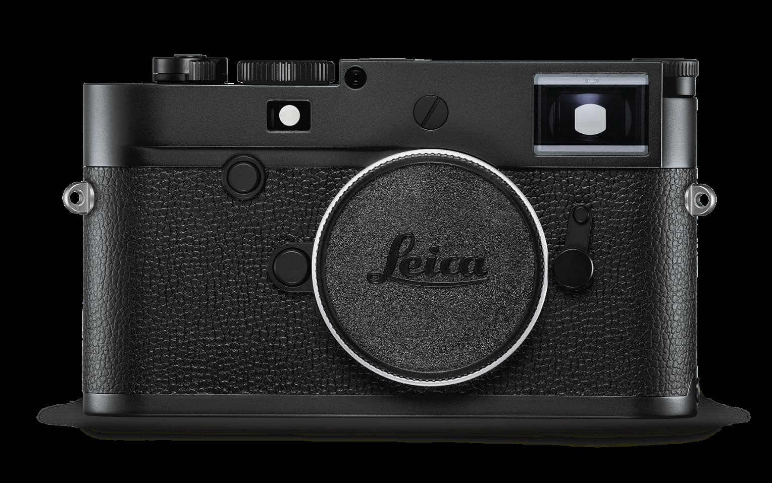
Click to zoom
Application Details
- Equipment Class
- DTS - Digital Transmission System
- Date of Grant
- Jan 16, 2020
- Application Purpose
- Original Equipment
- Date of Application
- Jan 16, 2020
- Equipment Note
- Digital camera
- Frequency Range
- 2412.00000000 - 2462.00000000
- Company
- Leica Camera AG
- Country
- Germany
Documents & Files
Document Text
Text extracted from the exhibit documents filed with the FCC. Open a document above to read the original.
Users Manual
LEICA 6376 QUICK START GUIDE Download the full scope instruction manual here: https://en.leica-camera.com/Service-Support/Support/Downloads Please register via the following link if you would like to receive a printed copy of the full scope instruction manual: www.order-instructions.leica-camera.com 15 16 17 18 19 30 20 21 26 27 22 24 23 1 2 3 4a 4 5 5 12 8 7 14 13 11 10 3a 9 6 28 TOP VIEW 1Main switch Switching the camera ON/OFF 2 Shutter button – Tap: activates exposure metering and control – Press down fully: the picture is taken – In standby mode: The camera is reactivated 3Shutter speed setting wheel with stop positions – A: Automatic shutter speed control – 8s - 4000: Shutter speeds (inc. intermediate values) – B: Long-term exposure (8 s - 4 min via menu control, in full increments or Bulb) – : Flash sync speed (1⁄180 s) aIndex 4ISO setting wheel – A: Automatic ISO sensitivity control – 100 - 6400: Fixed ISO values – M: Manual ISO sensitivity control aIndex 1 2 2 5Strap lugs 66-bit encoding sensor for lens detection 7Bayonet 8Lens release button 1 2 1 2 9Focus button 10Rangefi nder viewing window 11Brightness sensor 12Viewfi nder viewing window 13Self-timer LED 14 Image fi eld selector for the selection of bright-line frame pairs 35/135 mm, 50/75 mm and 28/90 mm 15LED for recording / data storage 16MENU button – for accessing the FAVORITES menu/ MAIN MENU – for exiting the FAVORITES menu, the MAIN MENU or any of the submenus 17PLAY button – for (continuous) playback mode activation/deactivation – for return to full-screen display 18LV button –for Live View mode activation/deactivation 19Brightness sensor for LCD panel 20Viewfi nder eyepiece 21LCD panel 22Directional pad – for menu navigation – for menu item/function selection – for scrolling through the picture memory 23Center button – to access the status display – to apply menu settings – to display settings/data during exposure – for display of picture data during picture review 24Thumbwheel – for menu navigation – for menu item/function selection – for exposure compensation value selection – for enlarging/reducing viewed pictures – for scrolling through the picture memory BOTTOM VIEW 25Locking toggle for bottom cover 1 3 2 4 26Tripod thread A ¼, DIN 4503 (¼”) 27Memory card slot 28Battery compartment 29Battery locking latch 30Bottom cover locking point CHARGING THE BATTERY A fl ashing green status LED indicates a correctly functioning charging process. A fully charged battery is indicated by a steady green light. DISPLAYS IN THE VIEWFINDER The bright-line frame rangefi nder of this camera is not just particularly bright viewfi nder – it also doubles as a lens-coupled rangefi nder. All Leica M lenses with focal lengths between 16 and 135 mm are coupled automatically. BA C 35 mm/135 mm 28 mm/90 mm ABright-line frame BMetering fi eld for focusing CDigital display 50 mm/75 mm FOCUSING SUPERIMPOSED IMAGE METHOD (DOUBLE IMAGE) out of focus in focus SPLIT IMAGE METHOD out of focus in focus DISPLAYS ON THE LCD PANEL 1 4 5 2 6 13 91011128 7 151614 3 1 Battery capacity 2 Exposure compensation scale 3 Remaining memory card capacity 4 ISO Sensitivity 5 Light balance 6 Shutter speed 7 White Balance mode 8 File format/compression level/resolution 9 Exposure metering method 10 Shutter button/Drive Mode 11 WLAN status 12 GPS status 13 User profi le 14 Exposure mode 15 Light intensity/focal length or lens type 16 Remaining number of pictures REVIEW SWITCHING BETWEEN PICTURE MODE/REVIEW 22:45 PM 22.02.2012 999-9000 8234/999912MP 2.8F1/800012500ISO EV INFO SCROLL MAGNIFY/REDUCE DELETE/RATE 22:45 PM 22.02.2012 999-9000 8234/999912MP 2.8F1/800012500ISO EV INFO All other operations are accessible by invoking the relevant function from the menu list. GESTURE CONTROL Tap briefl y Tap twice horizontal/vertical swipe Two-fi nger pinch/spread PICTURES FOCUS AID IN LIVE VIEW 22:45 PM 22.02.2012 999-9000 8234/999912MP 2.8F1/800012500ISO EV INFO SHIFT FOCUS POINT FOR FOCUS AID 1 AND EXPOSURE METERING 2 1 Focus Aid is activated by turning the lens 2 In combination with spot exposure metering MENU OVERVIEW Factory settings FAVORITES Available for FAVORITES Lens Detection 6 Drive Mode 66 Exp. Metering 6 Exp. Compensation 66 Flash Settings 66 ISO Setup 6 6 M-ISO also available White Balance 66 File Format 66 JPG Settings 6 6 JPG Resolution also available Auto Review 6 Capture Assistants 6 EVF/Display Control 6 User Profiles 6 Load Profile also available Customize Control 6 Display Brightness 6 EVF Brightness 6 Auto Power Saving 6 WLAN 6 GPS 1 6 Date & Time 6 Language 6 Reset Camera 6 Format SD card 6 Image Numbering 6 Sensor Cleaning 6 Camera Information 6 1 This menu item is only available if the Leica Visoflex viewfinder is attached (available as an accessory). JOINING A WLAN ▸Select WLAN in the main menu ▸Select Connection in the same submenu ▸Select Join WLAN ▸Select Configuration in the same submenu ▸Select the desired WLAN from the network list or enter a hidden network via the Add network option ▸Press the center button to confirm the selected network DIRECT CONNECTION WITHOUT WLAN ▸Select WLAN in the main menu ▸Activate (ON) Function in the submenu ▸Select Connection in the same submenu ▸Select Create WLAN TECHNICAL DATA Camera name Leica 6376 Camera type Digital camera with rangefinder system Type No. 6376 Order No. 20 002 (black), 20 003 (silver) Lens mount Leica M bayonet Compatible lenses Leica M lenses, Leica R lenses via adapter Sensor CMOS chip, active surface approx. 24 x 36 mm Storage media SD cards 1-2 GB / SDHC cards up to 32 GB / SDXC cards up to 2 TB Viewfinder Large, bright-line frame rangefinder and automatic parallax compensation LCD panel 3” TFT LCD, 1.04 MP, touch control available WLAN The Leica FOTOS app is required to use of the WLAN function. The Leica app is available from the Apple App Store™ or the Google Play Store™. Complies with WiFi standard IEEE802.11b/g/n, 2.4 GHz, channel 1-11, frequency range 2412-2462 MHz, max. output po…
Text truncated - open the document above for the full version.
External Photos
Photos External View – LEICA Model 6376 Prepared: P. Schober (EE) Date: Jan. 22, 2020 Photos External View – LEICA Model 6376 Prepared: P. Schober (EE) Date: Jan. 22, 2020
ID Label/Location Info
Druckvorlage für Klebeschild LEICA M10-R Type No.: 6376 420-302.050-090 ÄZ:3 08. Mai 2019 K. Pfeiffer
ID Label/Location Info
Date: May 27, 2019 E-Label –6376
Internal Photos
Photos Electronic – LEICA - Model 6376 Prepared: P. Schober (EE) Date: Jan. 09, 2020 Imaging Photos Electronic – LEICA - Model 6376 Prepared: P. Schober (EE) Date: Jan. 09, 2020 Sensor Board Photos Electronic – LEICA - Model 6376 Prepared: P. Schober (EE) Date: Jan. 09, 2020 Power Photos Electronic – LEICA - Model 6376 Prepared: P. Schober (EE) Date: Jan. 09, 2020 RS - LCD Photos Electronic – LEICA - Model 6376 Prepared: P. Schober (EE) Date: Jan. 09, 2020 WLAN Photos Electronic – LEICA - Model 6376 Prepared: P. Schober (EE) Date: Jan. 09, 2020 WLAN Antenna Antenna Cable Photos Electronic – LEICA - Model 6376 Prepared: P. Schober (EE) Date: Jan. 09, 2020 DK Top Cover Photos Electronic – LEICA - Model 6376 Prepared: P. Schober (EE) Date: Jan. 09, 2020 H Mainboard Photos Electronic – LEICA - Model 6376 Prepared: P. Schober (EE) Date: Jan. 09, 2020 VSOK Shutter + Lens detection
Test Report
D - P L - 1 2 0 7 6 - 0 1 - 0 3 BNetzA - CAB - 02/21 - 102 TEST REPORT Test report no.: 1-7938/19-02-06-A Testing laboratory Applicant CTC advanced GmbH Untertuerkheimer Strasse 6 – 10 66117 Saarbruecken / Germany Phone: + 49 681 5 98 - 0 Fax: + 49 681 5 98 - 9075 Internet: http://www.ctcadvanced.com e-mail: [email protected] Accredited Testing Laboratory: The testing laboratory (area of testing) is accredited according to DIN EN ISO/IEC 17025 (2005) by the Deutsche Akkreditierungsstelle GmbH (DAkkS) The accreditation is valid for the scope of testing procedures as stated in the accreditation certificate with the registration number: D-PL-12076-01-03 Leica Camera AG Am Leitz-Park 5 35578 Wetzlar / GERMANY Phone: -/- Contact: Peter Schober e-mail: [email protected] Phone: +49 6441 2080-672 Manufacturer Leica Camera AG Am Leitz-Park 5 35578 Wetzlar / GERMANY Test standard/s FCC - Title 47 CFR Part 15 FCC - Title 47 of the Code of Federal Regulations; Chapter I; Part 15 - Radio frequency devices RSS - 247 Issue 2 Digital Transmission Systems (DTSs), Frequency Hopping Systems (FHSs) and Licence - Exempt Local Area Network (LE-LAN) Devices For further applied test standards please refer to section 3 of this test report. Test Item Kind of test item: Digital Camera Model name: 6376 FCC ID: N5A6376 IC: 11245A-6376 Frequency: DTS band 2400 MHz to 2483.5 MHz Technology tested: WLAN Antenna: PCB antenna Power supply: 7.4 V DC by Li-Ion rechargeable battery Temperature range: 0°C to +40°C This test report is electronically signed and valid without handwritten signature. For verification of the electronic signatures, the public keys can be requested at the testing laboratory. Test report authorized: Test performed: David Lang Mihail Dorongovskij Lab Manager Lab Manager Radio Communications & EMC Radio Communications & EMC Test report no.: 1-7938/19-02-06-A © CTC advanced GmbH Page 2 of 93 1 Table of contents 1 Table of contents ............................................................................................................................................ 2 2 General information ....................................................................................................................................... 3 2.1 Notes and disclaimer .......................................................................................................................... 3 2.2 Application details ............................................................................................................................... 3 2.3 Test laboratories sub-contracted ...................................................................................................... 3 3 Test standard/s ............................................................................................................................................... 4 4 Test environment ............................................................................................................................................ 4 5 Test item .......................................................................................................................................................... 5 5.1 General description ............................................................................................................................. 5 5.2 Additional information ........................................................................................................................ 5 6 Description of the test setup ......................................................................................................................... 6 6.1 Shielded semi anechoic chamber ...................................................................................................... 7 6.2 Shielded fully anechoic chamber ...................................................................................................... 8 6.3 Radiated measurements > 18 GHz ..................................................................................................... 9 6.4 Conducted measurements with peak power meter & spectrum analyzer ................................... 10 7 Sequence of testing ..................................................................................................................................... 11 7.1 Sequence of testing radiated spurious 9 kHz to 30 MHz ............................................................... 11 7.2 Sequence of testing radiated spurious 30 MHz to 1 GHz .............................................................. 12 7.3 Sequence of testing radiated spurious 1 GHz to 18 GHz .............................................................. 13 7.4 Sequence of testing radiated spurious above 18 GHz .................................................................. 14 8 Measurement uncertainty ............................................................................................................................ 15 9 Summary of measurement results ............................................................................................................. 16 10 Additional comments ............................................................................................................................ 17 11 Additional EUT parameter .................................................................................................................... 18 12 Measurement results ............................................................................................................................ 19 12.1 Antenna gain .................................................................................................................................. 19 12.2 Identify worst case data rate ........................................................................................................ 20 12.3 Maximum output power .............................................................................…
Text truncated - open the document above for the full version.
Test Report
© CTC advanced GmbH Page 1 of 30 BNetzA-CAB-02/21-102 D-PL-12076-01-03 TEST REPORT Test Report No.: 1-7938/19-02-08 Testing Laboratory Applicant CTC advanced GmbH Untertuerkheimer Strasse 6 – 10 66117 Saarbruecken/Germany Phone: + 49 681 5 98 - 0 Fax: + 49 681 5 98 - 9075 Internet: http://www.ctcadvanced.com e-mail: [email protected] Accredited Test Laboratory: The testing laboratory (area of testing) is accredited according to DIN EN ISO/IEC 17025 (2005) by the Deutsche Akkreditierungsstelle GmbH (DAkkS) The accreditation is valid for the scope of testing procedures as stated in the accreditation certificate with the registration number: D-PL-12076-01-03 Leica Camera AG Am Leitz-Park 5 35578 Wetzlar/GERMANY Contact: Peter Schober e-mail: [email protected] Phone: +49 6441 2080-672 Fax: +49 6441 2080-170 Manufacturer Leica Camera AG Am Leitz-Park 5 35578 Wetzlar/GERMANY Test Standards IEEE 1528-2013 Recommended Practice for Determining the Peak Spatial-Average Specific Absorption Rate (SAR) in the Human Head from Wireless Communications Devices: Measurement Techniques RSS-102 Issue 5 Radio Frequency Exposure Compliance of Radiocommunication Apparatus (All Frequency Bands) For further applied test standards please refer to section 3 of this test report. Test Item Kind of test item: Digital Camera Device type: portable device Model name: 6376 S/N serial number: radiated: P 02 conducted: P 10 FCC-ID: N5A6376 IC: 11245A-6376 Product Marketing Name (PMN): 6376 Hardware Version Identification No. (HVIN): 6376 Hardware status: -/- Software status: -/- Firmware status: 9.0.0.0 Frequency: see technical details Antenna: Integrated PCB Antenna Battery option: Li-Ion rechargeable Battery Accessories: metal cover, thumb support, handgrip, flashlight SF 40, Visoflex (see external photos in Annex C) Test sample status: identical prototype Exposure category: general population / uncontrolled environment This test report is electronically signed and valid without handwriting signature. For verification of the electronic signatures, the public keys can be requested at the testing laboratory. Test Report authorised: Test performed: Alexander Hnatovskiy Marco Scigliano Lab Manager Testing Manager Radio Communications & EMC Radio Communications & EMC Test report no.: 1-7938/19-02-08 © CTC advanced GmbH Page 2 of 30 1 Table of contents 1 Table of contents ....................................................................................................................................... 2 2 General information .................................................................................................................................. 3 2.1 Notes and disclaimer ..................................................................................................................... 3 2.2 Application details ......................................................................................................................... 3 2.3 Statement of compliance ............................................................................................................... 3 2.4 Technical details ............................................................................................................................ 4 3 Test standards/ procedures references .................................................................................................. 5 3.1 RF exposure limits ......................................................................................................................... 6 4 Summary of Measurement Results ......................................................................................................... 7 5 Test Environment ...................................................................................................................................... 7 6 Test Set-up ................................................................................................................................................. 8 6.1 Measurement system ..................................................................................................................... 8 6.1.1 System Description ................................................................................................................ 8 6.1.2 Test environment ................................................................................................................... 9 6.1.3 Probe description ................................................................................................................... 9 6.1.4 Phantom description ............................................................................................................ 10 6.1.5 Device holder description .................................................................................................... 11 6.1.6 Scanning procedure ............................................................................................................ 12 6.1.7 Spatial Peak SAR Evaluation .............................................................................................. 13 6.1.8 Data Storage and Evaluation............................................................................................... 14 6.1.9 Tissue simulating liquids: dielectric properties .................................................................... 16 6.1.10 Tissue simulating liquids: parameters ................................................................................. 16 6.1.11 Measurement uncertainty evaluation for SAR test .............................................................. 17 6.1.12 Measurement uncertainty evaluation for System Check ..................................................... 20 6.1.13 System check ...................................................................................................................... 21 6.1.14 System check procedure ..............................................................................…
Text truncated - open the document above for the full version.
Test Report
Page 1 of 29 Annex D Appendix to Test Report No.: 1-7938/19-02-08 Testing Laboratory CTC advanced GmbH Untertürkheimer Straße 6 – 10 66117 Saarbrücken/Germany Phone: + 49 681 5 98 - 0 Fax: + 49 681 5 98 - 9075 Internet: http://www.ctcadvanced.com e-mail: [email protected] Accredited Test Laboratory: The testing laboratory (area of testing) is accredited according to DIN EN ISO/IEC 17025 (2005) by the Deutsche Akkreditierungsstelle GmbH (DAkkS) The accreditation is valid for the scope of testing procedures as stated in the accreditation certificate with the registration number: D-PL-12076-01-01 Appendix with Calibration data, Phantom certificate and system check information 2012-01-16 Test report no.: 1-7938/19-02-08 Page 2 of 29 1 Table of contents 1 Table of contents ....................................................................................................................................... 2 2 Calibration report “Probe EX3DV4” ........................................................................................................ 3 3 Calibration report “2450 MHz System validation dipole” .................................................................... 13 4 Calibration certificate of Data Acquisition Unit (DAE) ........................................................................ 21 5 Certificate of “SAM Twin Phantom V4.0/V4.0C’’ ................................................................................. 22 6 Application Note System Performance Check ..................................................................................... 23 6.1 Purpose of system performance check ..................................................................................... 23 6.2 System Performance check procedure ...................................................................................... 23 6.3 Uncertainty Budget ...................................................................................................................... 24 6.4 Power set-up for validation ......................................................................................................... 28 6.5 Laboratory reflection ................................................................................................................... 29 6.6 Additional system checks ........................................................................................................... 29 Test report no.: 1-7938/19-02-08 Page 3 of 29 2 Calibration report “Probe EX3DV4” Test report no.: 1-7938/19-02-08 Page 4 of 29 Test report no.: 1-7938/19-02-08 Page 5 of 29 Test report no.: 1-7938/19-02-08 Page 6 of 29 Test report no.: 1-7938/19-02-08 Page 7 of 29 Test report no.: 1-7938/19-02-08 Page 8 of 29 Test report no.: 1-7938/19-02-08 Page 9 of 29 Test report no.: 1-7938/19-02-08 Page 10 of 29 Test report no.: 1-7938/19-02-08 Page 11 of 29 Test report no.: 1-7938/19-02-08 Page 12 of 29 Test report no.: 1-7938/19-02-08 Page 13 of 29 3 Calibration report “2450 MHz System validation dipole” Test report no.: 1-7938/19-02-08 Page 14 of 29 Test report no.: 1-7938/19-02-08 Page 15 of 29 Test report no.: 1-7938/19-02-08 Page 16 of 29 Test report no.: 1-7938/19-02-08 Page 17 of 29 Test report no.: 1-7938/19-02-08 Page 18 of 29 Test report no.: 1-7938/19-02-08 Page 19 of 29 Test report no.: 1-7938/19-02-08 Page 20 of 29 Test report no.: 1-7938/19-02-08 Page 21 of 29 4 Calibration certificate of Data Acquisition Unit (DAE) Test report no.: 1-7938/19-02-08 Page 22 of 29 5 Certificate of “SAM Twin Phantom V4.0/V4.0C’’ Test report no.: 1-7938/19-02-08 Page 23 of 29 6 Application Note System Performance Check 6.1 Purpose of system performance check The system performance check verifies that the system operates within its specifications. System and operator errors can be detected and corrected. It is recommended that the system performance check is performed prior to any usage of the system in order to guarantee reproducible results. The measurement of the Specific Absorption Rate (SAR) is a complicated task and the result depends on the proper functioning of many components and the correct settings of many parameters. Faulty results due to drift, failures or incorrect parameters might not be recognized, since they often look similar in distribution to the correct ones. The Dosimetric Assessment System DASY5 incorporates a system performance check procedure to test the proper functioning of the system. The system performance check uses normal SAR measurements in a simplified setup (the flat section of the SAM Twin Phantom) with a well characterized source (a matched dipole at a specified distance). This setup was selected to give a high sensitivity to all parameters that might fail or vary over time (e.g., probe, liquid parameters, and software settings) and a low sensitivity to external effects inherent in the system (e.g., positioning uncertainty of the device holder). The system performance check does not replace the calibration of the components. The accuracy of the system performance check is not sufficient for calibration purposes. It is possible to calculate the field quite accurately in this simple setup; however, due to the open field situation some factors (e.g., laboratory reflections) cannot be accounted for. Calibrations in the flat phantom are possible with transfer calibration methods, using either temperature probes or calibrated E-field probes. The system performance check also does not test the system performance for arbitrary field situations encountered during real measurements of mobile phones. These checks are performed at SPEAG by testing the components under various conditions (e.g., spherical isotropy measurements in liquid, linearity measurements, temperature variations, etc.), the results of which are used for an error estimation of the system. The system performance check will indicate situations where the system uncertainty is exceeded due to drift or failure. 6.2 System Performance check proce…
Text truncated - open the document above for the full version.
Test Report
Page 1 of 8 BNetzA-CAB-02/21-102 Annex C Photo documentation Appendix to Test Report No.: 1-7938/19-02-08 Testing Laboratory CTC advanced GmbH Untertürkheimer Straße 6 – 10 66117 Saarbrücken/Germany Phone: + 49 681 5 98 - 0 Fax: + 49 681 5 98 - 9075 Internet: http://www.ctcadvanced.com e-mail: [email protected] Accredited Test Laboratory: The testing laboratory (area of testing) is accredited according to DIN EN ISO/IEC 17025 (2005) by the Deutsche Akkreditierungsstelle GmbH (DAkkS) The accreditation is valid for the scope of testing procedures as stated in the accreditation certificate with the registration number: D-PL-12076-01-03 D-PL-12076-01-03 Test report no.: 1-7938/19-02-08 Page 2 of 8 Photo 1: Measurement System DASY 5 Photo 2: DUT – front view Test report no.: 1-7938/19-02-08 Page 3 of 8 Photo 3: DUT - rear view Photo 4: DUT - top view WLAN antenna WLAN antenna Test report no.: 1-7938/19-02-08 Page 4 of 8 Photo 5: Accessories overview Photo 6: Test position bottom side metall cover thumb support Visoflex flashlight SF 40 handgrip Test report no.: 1-7938/19-02-08 Page 5 of 8 Photo 7: Test position rear side Photo 8: Test position rear 30° Test report no.: 1-7938/19-02-08 Page 6 of 8 Photo 9: Test position rear 30° Photo 10: Test position rear 30° with metal cover Test report no.: 1-7938/19-02-08 Page 7 of 8 Photo 11: Test position rear 30° with thumb support Photo 12: Test position rear 30° with handgrip Test report no.: 1-7938/19-02-08 Page 8 of 8 Photo 13: Test position rear 30° with Flash SF 40 Photo 14: Test position rear 30° with Visoflex
Test Setup Photos
Annex D 1-7938/19-02-01_AnnexD Setup photos of the Equipment Under Test This addendum is electronically signed and valid without handwritten signature. For verification of the electronic signatures, the public keys can be requested at the testing laboratory. Document authorized: Mihail Dorongovskij Lab Manager Radio Communications & EMC CTC advanced GmbHUntertuerkheimer Str. 6-10 66117 Saarbruecken / Germany Phone: +49 681 5 98 - 0 Fax: +49 681 5 98 - 9075 web: ctcadvanced.com e-mail: [email protected] Photos Photo 1: EUT at the anechoic chamber Photo 2: EUT at the anechoic chamber 2019-05-23Document No. 1-7938/19-02-01_AnnexD2/6 Photo 3: EUT at the anechoic chamber Photo 4: EUT at the anechoic chamber 2019-05-23Document No. 1-7938/19-02-01_AnnexD3/6 Photo 5: EUT at the anechoic chamber Photo 6: EUT at the anechoic chamber 2019-05-23Document No. 1-7938/19-02-01_AnnexD4/6 Photo 7: EUT at the semi-anechoic chamber 2019-05-23Document No. 1-7938/19-02-01_AnnexD5/6 Document history VersionApplied changesDate of release initial release2019-05-23 - END OF DOCUMENT - 2019-05-23Document No. 1-7938/19-02-01_AnnexD6/6
Contact Information
Applicant
Peter Schober(Design Engineer Electronics)
Test Firm
cetecom advanced GmbHGerald Schmidt
Technical Specifications
| # | Rule Parts | Frequency Range | Power Output |
|---|---|---|---|
| 1 | 15C | 2.41 GHz - 2.46 GHz | 39.80 mW |
Other Applications from Leica Camera AG
N5A6939
Jul 17, 2026Binocular with Laser Rangefinder
Equipment Class
DTS - Digital Transmission System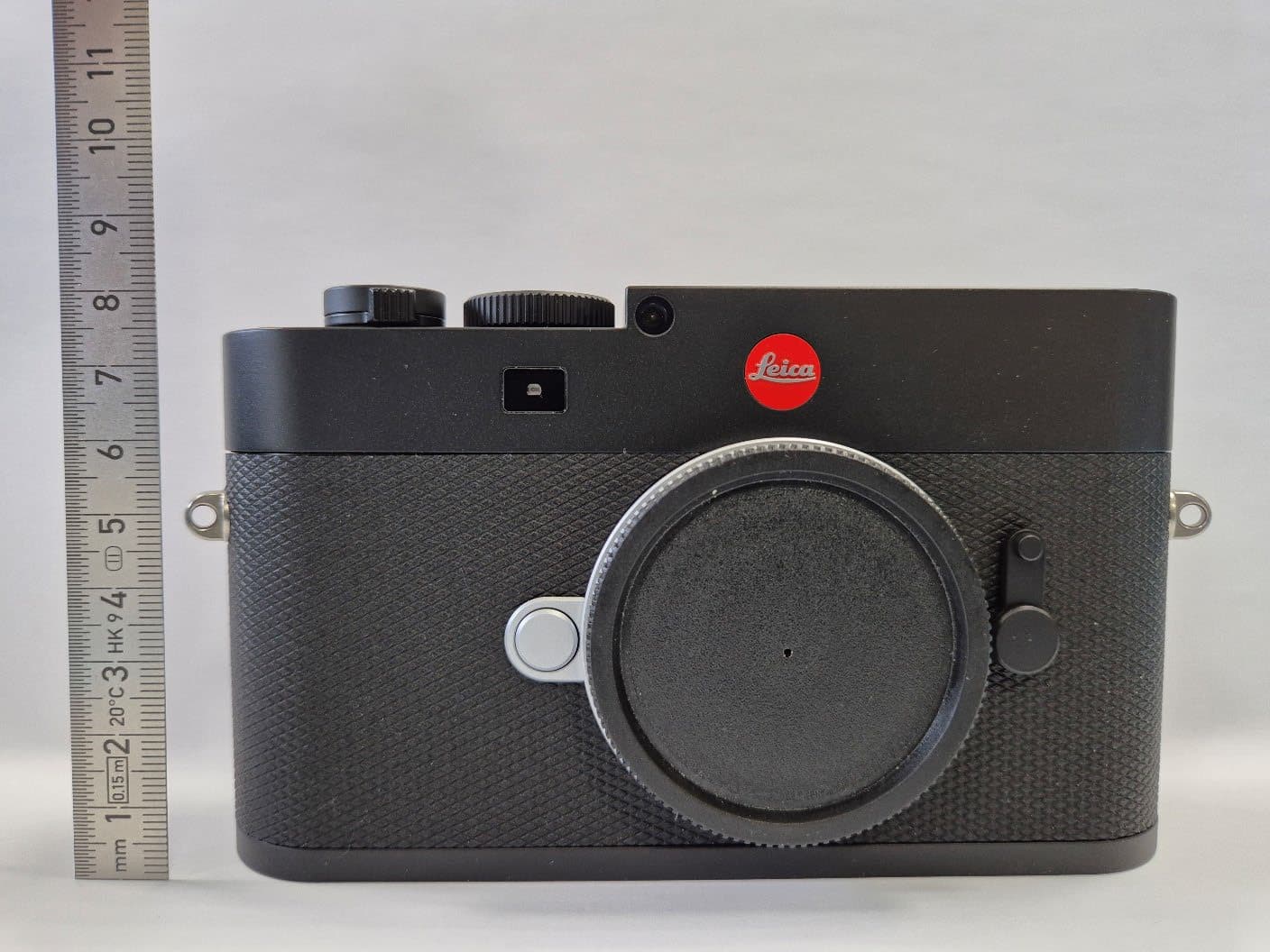
N5A4246
Nov 18, 2025Digital Camera
Equipment Class
NII - Unlicensed National Information Infrastructure TX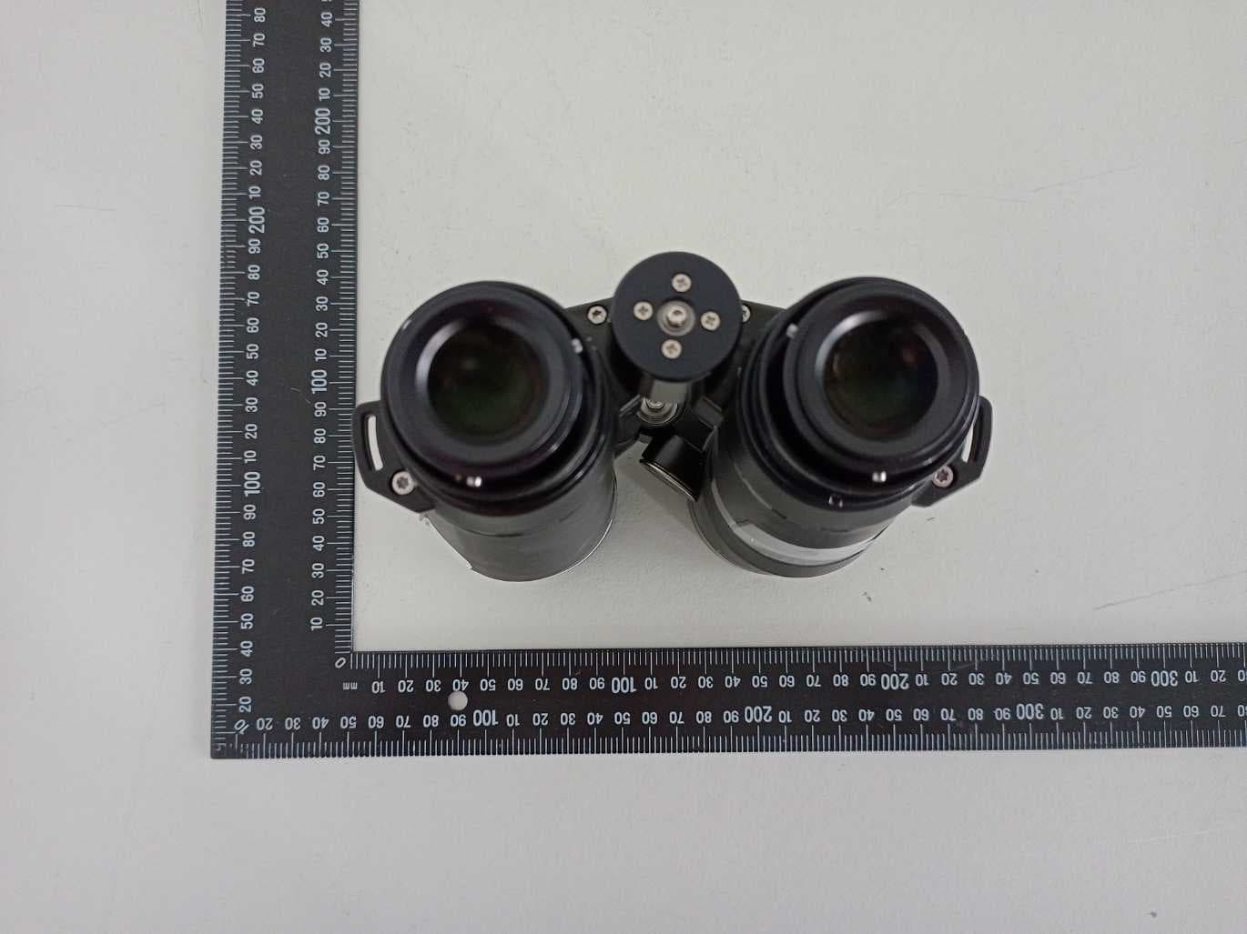
N5A6931
Jan 04, 2023Binocular with Laser Rangefinder
Equipment Class
DTS - Digital Transmission System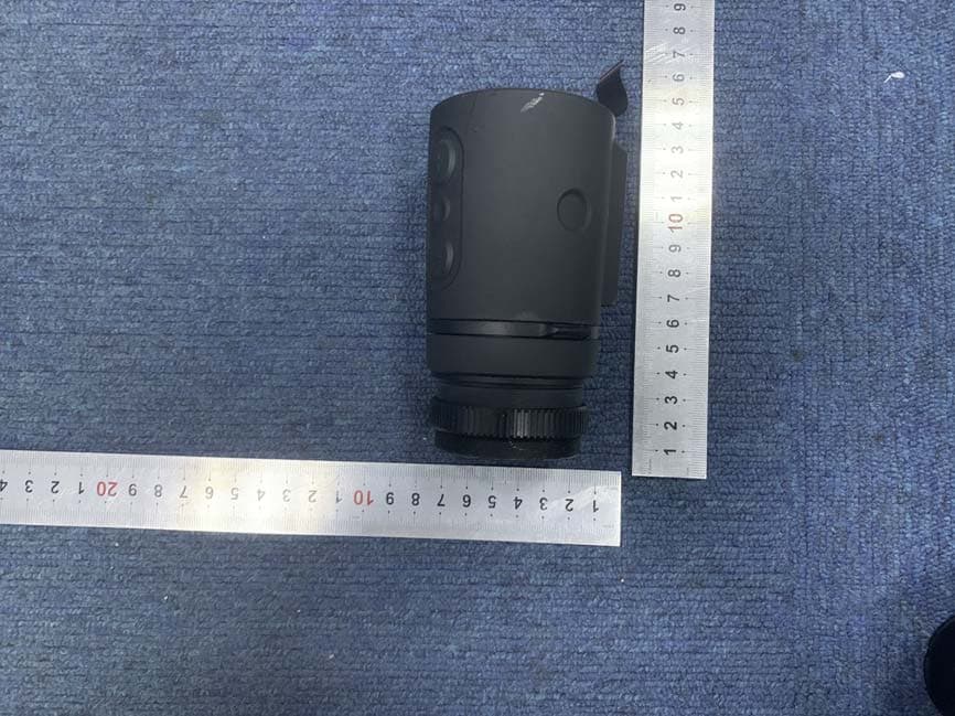
N5A1970
Oct 21, 2020Thermal Imaging Device
Equipment Class
DTS - Digital Transmission System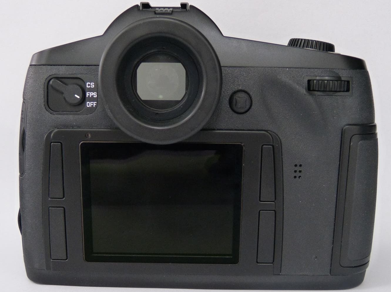
N5AS007
Aug 03, 2015Camera
Equipment Class
DTS - Digital Transmission System