N5AS007Camera
Leica Camera AG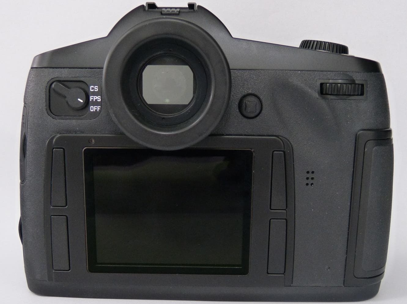
Click to zoom
Application Details
- Equipment Class
- DTS - Digital Transmission System
- Date of Grant
- Aug 03, 2015
- Application Purpose
- Original Equipment
- Date of Application
- Aug 03, 2015
- Equipment Note
- Camera
- Frequency Range
- 2412.00000000 - 2462.00000000
- Company
- Leica Camera AG
- Country
- Germany
Documents & Files
Document Text
Text extracted from the exhibit documents filed with the FCC. Open a document above to read the original.
Users Manual
Leica S Instructions EN 2 FOREWORD Dear Customer, Leica would like to thank you for purchasing the Leica S and congratulate you on your choice. With this unique medium-format digital SLR camera, you have made an excellent choice. We wish you a great deal of pleasure and success using your new Leica S. In order to make best use of all the opportunities offered by this high performance camera, we recommend that you first read this instruction manual. Your Leica Camera AG Note: Leica is constantly working on developing and optimizing the Leica S. As many functions on digital cameras are controlled purely electronically, improvements and extensions to the range of functions may need to be installed on the camera at a later date. To do this, Leica releases what are known as firmware updates at irregular intervals. Cameras are always supplied from the factory with the latest firmware, but you can easily download the updates to your camera yourself from our website. If you register as an owner on the Leica Camera website, you will receive a newsletter informing you when a new firmware update is available. Further information on registration and on firmware updates for your Leica S and on any changes or additions to the details in this manual can be found on our website under "Customer Service" at: https://owners.leica-camera.com To check whether your camera and lenses are running the latest firmware version, select menu option "Firmware" (see p. 66, 16-19). Foreword EN 3 FCC Note: This equipment has been tested and found to comply with the limits for a Class B digital device, pursuant to Part 15 of the FCC Rules. These limits are designed to provide reasonable protection against harmful interfer- ence in a residential installation. This equipment generates, uses, and can radiate radio frequency energy and, if not installed and used in accor- dance with the instructions, may cause harmful interference to radio com- munications. However, there is no guarantee that interference will not occur in a particular installation. If this equipment does cause harmful interference to radio or television reception, which can be determined by turning the equipment off and on, the user is encouraged to try to correct the interference by one or more of the following measures: • Reorient or relocate the receiving antenna. • Increase the separation between the equipment and receiver. • Connect the equipment into an outlet on a circuit different from that to which the receiver is connected. • Consult the dealer or an experienced radio/TV technician for help. FCC Caution: To assure continued compliance, follow the attached installation instruc- tions and use only shielded inter face cables with ferrite core when con- necting to com put er or peripheral devices. Any changes or modifications not expressly approved by the party responsible for compliance could void the user’s authority to operate this equipment. Trade Name: LEICA Model No.: LEICA S (Typ 007) Responsible party/ Support contact: Leica Camera Inc. 1 Pearl Count, Unit A Allendale, New Jersey 07401 Tel.: +1 201 995 0051 Fax: +1 201 995 1684 [email protected] This device complies with Part 15 of the FCC Rules. Operation is subject to the following two conditions: (1) This device may not cause harmful interference, and (2) this device must accept any interference received, including interference that may cause undesired operation. LEICA S (Typ 007) Tested To Comply With FCC Standards FOR HOME OR OFFICE USE Contains FCC ID: N5AS007 This transmitter must not be co-located or operated in conjunction with any other antenna or transmitter. This equipment complies with FCC radiation exposure limits set forth for an uncontrolled environment and meets the FCC radio frequency (RF) Exposure Guidelines. This equipment has very low levels of RF energy that are deemed to comply without testing of specific absorption ratio (SAR). For Canada only: CAN ICES-3 (B)/NMB-3(B) This device complies with RSS-210 of the IC Rules. Operation is subject to the following two conditions: (1) This device may not cause harmful interference, (2) This device must accept any interference received, including interfer- ence that may cause undesired operation of the device. This equipment complies with IC radiation exposure limits set forth for an uncontrolled environment and meets RSS-102 of the IC radio frequency (RF) Exposure rules. This equipment has very low levels of RF energy that are deemed to comply without testing of specific absorption ratio (SAR). EN 4 Table of contents TABLE OF CONTENTS Foreword ..............................................................................................2 Warning messages ................................................................................6 CE mark ................................................................................................6 Legal information ..................................................................................6 Disposal of electrical and electronic equipment .....................................6 Package contents .................................................................................6 Designation of parts ..............................................................................7 Preparations Attaching the carrying strap ................................................................8 Charging the battery ...........................................................................8 Inserting and removing the battery into/from the camera .................11 Charge level displays ........................................................................11 Changing memory cards ...................................................................11 Changing the focusing screen ...........................................................13 Leica S lenses ..................................................................................14 Fitting and removing ........................…
Text truncated - open the document above for the full version.
Users Manual
EN 35 Recording mode Aborting the function A running self-timer delay time can be aborted by turning off the camera at the main switch. A running 12 s self-timer delay time can also be aborted during the first 10 s by pressing any of the four buttons next to the monitor. If the self-timer is no longer to be used, it must be switched off in the menu, as even switching off the camera does not cancel the setting of this function. Note: If the self-timer function is set and the mirror lock-up activated (see next section) at the same time, the shutter is always actuated after the selected delay time, i.e. without the shutter button having to be pressed again. Mirror lock-up In order to preclude the minimal residual influences of mirror movement and closing of the lens shutter, the Leica S offers the possibility of the mirror lock-up. Setting / performing the function 1. In the menu, under CAMERA , select the item Mirror Up Mode and 2. select On or O ff in the sub-menu. 3. Press the shutter button to cause the mirror to be folded up 4. Press the shutter button again to take the picture Procedure When the shutter button is pressed the first time, exposure metering is performed, in autofocus mode the focus is adjusted, then the mirror is folded up and the aperture closes to the corresponding value. The shutter procedure - and hence the taking of the picture - starts only when the shutter button is pressed a second time. After the picture is taken, the mirror is folded down again and the aper- ture opens in the normal way. Aborting the function The mirror lock-up procedure can be aborted without a picture being taken after the shutter button is pressed the first time. Simply switch off the camera at the main switch and the mirror is folded down again. If the mirror lock-up is set, on the other hand, the function remains active even after turning the camera off and on again, i.e. if the next picture is to be taken without mirror lock-up, the function must be set to O ff in the menu. Notes: • The picture must be taken within 2 minutes of the shutter button being pressed the first time. If this is not the case, the mirror is folded down again automatically to protect the battery capacity (without the shutter opening beforehand). • While the mirror is folded up, the 2 minutes holding time can be restarted at any time by pressing the shutter button again. • If the mirror lock-up is activated and the self-timer function set at the same time, the shutter is always actuated after the selected delay time, i.e. without the shutter button having to be pressed again. Depth of field preview button With the Leica S you can close the lens aperture to the set or automati- cally controlled aperture value in any exposure mode. In the factory setting, this is done with the depth of field preview button. The correct values continue to be displayed in the monitor and top panel display, and in Live View mode also in the monitor. However, exposure metering is deactivated. Preconditions for closure of the lens aperture are – Exposure metering has been activated with the shutter button, and – The shutter button has not been pressed (again). The shutter is blocked as long as the button is held depressed. Note: The function of the depth of field preview button differs, depending on the operating mode: Operating modeFunction Photo modeNormal, i.e. use of the viewfinder image Close the aperture by holding the button depressed or quick access to the set menu function by pressing Live View, i.e. use of the viewfinder image Activating/deactivating exposure simulation by (multiple) pressing Video preview and recording modeAccess to setting the audio recording level and the headphone volume by holding depressed, function independent of the setting for normal photography mode and cannot be changed EN 36 Recording mode ADDITIONAL FUNCTIONS USER / APPLICATION-SPECIFIC PROFILES On the Leica S, any combination of menu settings can be permanently stored, e.g. so that they can be retrieved quickly and easily at any time for recurring situations / subjects. A total of four memory slots are available for these combinations, as well as a factory default setting that can be retrieved at any time and cannot be changed. You can change the names of the saved profiles. Profiles set on the camera can be trans- ferred to one of the memory cards, for example for use in other camera units, while profiles stored on a card can be transferred onto the camera. Saving settings / Creating a profile 1. Set the desired functions in the menu 2. In the menu, under SETUP , select the item User Profiles and 3. select Save as User Profile in the sub-menu • A further sub-menu appears with four lines for the available profile slots. 4. In this sub-menu, select the desired memory slot • A corresponding confirmation prompt appears 5. Confirm Ye s or cancel No your selection there • The sub-menu from step 4. appears again, and the selected mem- ory slot is marked as occupied. Selecting a profile 1. In the menu, under SETUP , select the item User Profiles and 2. select Load Profile in the sub-menu • A further sub-menu appears with five lines, the first for the factory settings, the others for the four profile slots. Only the lines with occupied profiles can be called up. 3. In this sub-menu, select the desired profile • The selected profile is marked as active. Note: If you change one of the settings for the profile currently in use --- appears instead of the name of the profile you were previously using in the initial menu list. Renaming profiles 1. In the menu, under SETUP , select the item User Profiles, and 2. select Rename User Profile in the sub-menu • A further sub-menu appears with four lines for the profile slots. Only the lines with occupied profiles can be called up. 3. Select the desired profile • A keyboard sub-menu is displayed. 4. First delete the existing designation in the title line there, then select the desired characters – Turning the rear thumbw…
Text truncated - open the document above for the full version.
External Photos
Photos External View - LEICA S (Typ 007) Prepared: P. Schber (EE) Date: Jul. 01, 2015 Photos External View - LEICA S (Typ 007) Prepared: P. Schber (EE) Date: Jul. 01, 2015 Photos External View - LEICA S (Typ 007) Prepared: P. Schber (EE) Date: Jul. 01, 2015 Photos External View - LEICA S (Typ 007) Prepared: P. Schber (EE) Date: Jul. 01, 2015
Internal Photos
Photos Electronic – LEICA S (Typ 007) STRICTLY CONFIDENTIAL Prepared: P. Schober (EE) Date: Jul. 01, 2015 Imaging Photos Electronic – LEICA S (Typ 007) STRICTLY CONFIDENTIAL Prepared: P. Schober (EE) Date: Jul. 01, 2015 CMOS Sensor Photos Electronic – LEICA S (Typ 007) STRICTLY CONFIDENTIAL Prepared: P. Schober (EE) Date: Jul. 01, 2015 H1 Photos Electronic – LEICA S (Typ 007) STRICTLY CONFIDENTIAL Prepared: P. Schober (EE) Date: Jul. 01, 2015 H2 Photos Electronic – LEICA S (Typ 007) STRICTLY CONFIDENTIAL Prepared: P. Schober (EE) Date: Jul. 01, 2015 H3 Photos Electronic – LEICA S (Typ 007) STRICTLY CONFIDENTIAL Prepared: P. Schober (EE) Date: Jul. 01, 2015 DK -Top cover Photos Electronic – LEICA S (Typ 007) STRICTLY CONFIDENTIAL Prepared: P. Schober (EE) Date: Jul. 01, 2015 DK-Display Photos Electronic – LEICA S (Typ 007) STRICTLY CONFIDENTIAL Prepared: P. Schober (EE) Date: Jul. 01, 2015 Power Photos Electronic – LEICA S (Typ 007) STRICTLY CONFIDENTIAL Prepared: P. Schober (EE) Date: Jul. 01, 2015 Shutter Motor Control Photos Electronic – LEICA S (Typ 007) STRICTLY CONFIDENTIAL Prepared: P. Schober (EE) Date: Jul. 01, 2015 WLAN Adapter Photos Electronic – LEICA S (Typ 007) STRICTLY CONFIDENTIAL Prepared: P. Schober (EE) Date: Jul. 01, 2015 WLAN Module Photos Electronic – LEICA S (Typ 007) STRICTLY CONFIDENTIAL Prepared: P. Schober (EE) Date: Jul. 01, 2015 WLAN Antenna Photos Electronic – LEICA S (Typ 007) STRICTLY CONFIDENTIAL Prepared: P. Schober (EE) Date: Jul. 01, 2015 GPS Photos Electronic – LEICA S (Typ 007) STRICTLY CONFIDENTIAL Prepared: P. Schober (EE) Date: Jul. 01, 2015 Display Connector Photos Electronic – LEICA S (Typ 007) STRICTLY CONFIDENTIAL Prepared: P. Schober (EE) Date: Jul. 01, 2015 Flash Sync Photos Electronic – LEICA S (Typ 007) STRICTLY CONFIDENTIAL Prepared: P. Schober (EE) Date: Jul. 01, 2015 Microphone Photos Electronic – LEICA S (Typ 007) STRICTLY CONFIDENTIAL Prepared: P. Schober (EE) Date: Jul. 01, 2015 Buttons Display left Photos Electronic – LEICA S (Typ 007) STRICTLY CONFIDENTIAL Prepared: P. Schober (EE) Date: Jul. 01, 2015 Buttons Display right Photos Electronic – LEICA S (Typ 007) STRICTLY CONFIDENTIAL Prepared: P. Schober (EE) Date: Jul. 01, 2015 USB Photos Electronic – LEICA S (Typ 007) STRICTLY CONFIDENTIAL Prepared: P. Schober (EE) Date: Jul. 01, 2015 Audio Connector
RF Exposure Info
Page 1 of 30 Annex D Appendix to Test Report No.: 1-9839/15-01-05 Testing Laboratory CETECOM ICT Services GmbH Untertürkheimer Straße 6 – 10 66117 Saarbrücken/Germany Phone: + 49 681 5 98 - 0 Fax: + 49 681 5 98 - 9075 Internet: http://www.cetecom.com e-mail: [email protected] Accredited Test Laboratory: The testing laboratory (area of testing) is accredited according to DIN EN ISO/IEC 17025 (2005) by the Deutsche Akkreditierungsstelle GmbH (DAkkS) The accreditation is valid for the scope of testing procedures as stated in the accreditation certificate with the registration number: D-PL-12076-01-01 Appendix with Calibration data, Phantom certificate and system check information 1899-12-30 Annex D to Test report no.: 1-9839/15-01-05 Page 2 of 30 1 Table of contents 1 Table of contents ....................................................................................................................................... 2 2 Calibration report “Probe ES3DV3” ........................................................................................................ 3 3 Calibration report “2450 MHz System validation dipole” .................................................................... 14 4 Calibration certificate of Data Acquisition Unit (DAE) ........................................................................ 22 5 Certificate of “SAM Twin Phantom V4.0/V4.0C’’ ................................................................................. 23 6 Application Note System Performance Check ..................................................................................... 24 6.1 Purpose of system performance check ..................................................................................... 24 6.2 System Performance check procedure ...................................................................................... 24 6.3 Uncertainty Budget ...................................................................................................................... 25 6.4 Power set-up for validation ......................................................................................................... 29 6.5 Laboratory reflection ................................................................................................................... 30 6.6 Additional system checks ........................................................................................................... 30 Annex D to Test report no.: 1-9839/15-01-05 Page 3 of 30 2 Calibration report “Probe ES3DV3” Annex D to Test report no.: 1-9839/15-01-05 Page 4 of 30 Annex D to Test report no.: 1-9839/15-01-05 Page 5 of 30 Annex D to Test report no.: 1-9839/15-01-05 Page 6 of 30 Annex D to Test report no.: 1-9839/15-01-05 Page 7 of 30 Annex D to Test report no.: 1-9839/15-01-05 Page 8 of 30 Annex D to Test report no.: 1-9839/15-01-05 Page 9 of 30 Annex D to Test report no.: 1-9839/15-01-05 Page 10 of 30 Annex D to Test report no.: 1-9839/15-01-05 Page 11 of 30 Annex D to Test report no.: 1-9839/15-01-05 Page 12 of 30 Annex D to Test report no.: 1-9839/15-01-05 Page 13 of 30 Annex D to Test report no.: 1-9839/15-01-05 Page 14 of 30 3 Calibration report “2450 MHz System validation dipole” Annex D to Test report no.: 1-9839/15-01-05 Page 15 of 30 Annex D to Test report no.: 1-9839/15-01-05 Page 16 of 30 Annex D to Test report no.: 1-9839/15-01-05 Page 17 of 30 Annex D to Test report no.: 1-9839/15-01-05 Page 18 of 30 Annex D to Test report no.: 1-9839/15-01-05 Page 19 of 30 Annex D to Test report no.: 1-9839/15-01-05 Page 20 of 30 Annex D to Test report no.: 1-9839/15-01-05 Page 21 of 30 Annex D to Test report no.: 1-9839/15-01-05 Page 22 of 30 4 Calibration certificate of Data Acquisition Unit (DAE) Annex D to Test report no.: 1-9839/15-01-05 Page 23 of 30 5 Certificate of “SAM Twin Phantom V4.0/V4.0C’’ Annex D to Test report no.: 1-9839/15-01-05 Page 24 of 30 6 Application Note System Performance Check 6.1 Purpose of system performance check The system performance check verifies that the system operates within its specifications. System and operator errors can be detected and corrected. It is recommended that the system performance check is performed prior to any usage of the system in order to guarantee reproducible results. The measurement of the Specific Absorption Rate (SAR) is a complicated task and the result depends on the proper functioning of many components and the correct settings of many parameters. Faulty results due to drift, failures or incorrect parameters might not be recognized, since they often look similar in distribution to the correct ones. The Dosimetric Assessment System DASY5 incorporates a system performance check procedure to test the proper functioning of the system. The system performance check uses normal SAR measurements in a simplified setup (the flat section of the SAM Twin Phantom) with a well characterized source (a matched dipole at a specified distance). This setup was selected to give a high sensitivity to all parameters that might fail or vary over time (e.g., probe, liquid parameters, and software settings) and a low sensitivity to external effects inherent in the system (e.g., positioning uncertainty of the device holder). The system performance check does not replace the calibration of the components. The accuracy of the system performance check is not sufficient for calibration purposes. It is possible to calculate the field quite accurately in this simple setup; however, due to the open field situation some factors (e.g., laboratory reflections) cannot be accounted for. Calibrations in the flat phantom are possible with transfer calibration methods, using either temperature probes or calibrated E-field probes. The system performance check also does not test the system performance for arbitrary field situations encountered during real measurements of mobile phones. These checks are performed at SPEAG by testing the components under various conditions (e.g., spherical isotropy mea…
Text truncated - open the document above for the full version.
RF Exposure Info
TEST REPORT Test Report No.: 1-9839/15-01-05 Testing Laboratory Applicant CETECOM ICT Services GmbH Untertürkheimer Straße 6 – 10 66117 Saarbrücken/Germany Phone: + 49 681 5 98 - 0 Fax: + 49 681 5 98 - 9075 Internet: http://www.cetecom.com e-mail: [email protected] Accredited Test Laboratory: The testing laboratory (area of testing) is accredited according to DIN EN ISO/IEC 17025 (2005) by the Deutsche Akkreditierungsstelle GmbH (DAkkS) The accreditation is valid for the scope of testing procedures as stated in the accreditation certificate with the registration number: D-PL-12076-01-00 Leica Camera AG Am Leitz-Park 5 35578 Wetzlar/GERMANY Phone: --- Contact: Peter Schober e-mail: [email protected] Phone: +49 6 44 12 08 06 72 Fax: +49 6 44 12 08 01 70 Manufacturer Leica Camera AG Am Leitz-Park 5 35578 Wetzlar/GERMANY Test Standard/s IEEE 1528-2003 Recommended Practice for Determining the Peak Spatial-Average Specific Absorption Rate (SAR)in the Human Head from Wireless Communications Devices: Measurement Techniques RSS-102 Issue 5 Radio Frequency Exposure Compliance of Radiocommunication Apparatus (All Frequency Bands) For further applied test standards please refer to section 3 of this test report. Test Item Kind of test item: Digital Camera Device type: portable device Model name: Leica S (Typ 007) S/N serial number: P - 116 FCC-ID: N5AS007 IC: 11245A-S007 Hardware status: 302 Software status: Firmware 0.0.9.7 (same RF-settings as firmware 0.15.25.0) Frequency: see technical details Antenna: integrated antenna Battery option: 7.3V / 2.85Ah Accessories: --- Test sample status: identical prototype Exposure category: general population / uncontrolled environment This test report is electronically signed and valid without handwriting signature. For verification of the electronic signatures, the public keys can be requested at the testing laboratory. Test Report authorised: Test performed: Oleksandr Hnatovskiy Marco Scigliano Lab Manager Testing Manager Radio Communications & EMC Radio Communications & EMC Test report no.: 1-9839/15-01-05 Page 2 of 41 1 Table of contents 1 Table of contents ............................................................................................................................................ 2 2 General information ....................................................................................................................................... 3 2.1 Notes and disclaimer ......................................................................................................................... 3 2.2 Application details ............................................................................................................................. 3 2.3 Statement of compliance .................................................................................................................. 3 2.4 Technical details ................................................................................................................................ 4 3 Test standards/ procedures references ....................................................................................................... 5 3.1 RF exposure limits ............................................................................................................................. 6 4 Summary of Measurement Results .............................................................................................................. 7 5 Test Environment ........................................................................................................................................... 7 6 Test Set-up ...................................................................................................................................................... 8 6.1 Measurement system ........................................................................................................................ 8 6.1.1 System Description .............................................................................................................................. 8 6.1.2 Test environment ................................................................................................................................. 9 6.1.3 Probe description ................................................................................................................................. 9 6.1.4 Phantom description .......................................................................................................................... 10 6.1.5 Device holder description .................................................................................................................. 11 6.1.6 Scanning procedure ........................................................................................................................... 12 6.1.7 Spatial Peak SAR Evaluation ............................................................................................................ 13 6.1.8 Data Storage and Evaluation ............................................................................................................. 14 6.1.9 Tissue simulating liquids: dielectric properties .................................................................................. 16 6.1.10 Tissue simulating liquids: parameters ........................................................................................... 17 6.1.11 Measurement uncertainty evaluation for SAR test ........................................................................ 18 6.1.12 Measurement uncertainty evaluation for System Check ............................................................... 21 6.1.13 System check................................................................................................................................. 22 6.1.14 System check procedure ............................................................................................................... 2…
Text truncated - open the document above for the full version.
RF Exposure Info
TEST REPORT Test Report No.: 1-9839/15-01-07 Testing Laboratory Applicant CETECOM ICT Services GmbH Untertürkheimer Straße 6 – 10 66117 Saarbrücken/Germany Phone: + 49 681 5 98 - 0 Fax: + 49 681 5 98 - 9075 Internet: http://www.cetecom.com e-mail: [email protected] Accredited Test Laboratory: The testing laboratory (area of testing) is accredited according to DIN EN ISO/IEC 17025 (2005) by the Deutsche Akkreditierungsstelle GmbH (DAkkS) The accreditation is valid for the scope of testing procedures as stated in the accreditation certificate with the registration number: D-PL-12076-01-00 Leica Camera AG Am Leitz-Park 5 35578 Wetzlar/GERMANY Phone: --- Contact: Peter Schober e-mail: [email protected] Phone: +49 6 44 12 08 06 72 Fax: +49 6 44 12 08 01 70 Manufacturer Leica Camera AG Am Leitz-Park 5 35578 Wetzlar/GERMANY Test Standard/s IEEE 1528-2003 Recommended Practice for Determining the Peak Spatial-Average Specific Absorption Rate (SAR)in the Human Head from Wireless Communications Devices: Measurement Techniques RSS-102 Issue 5 Radio Frequency Exposure Compliance of Radiocommunication Apparatus (All Frequency Bands) For further applied test standards please refer to section 3 of this test report. Test Item Kind of test item: Digital Camera Device type: portable device Model name: Leica S (Typ 007) S/N serial number: P - 116 FCC-ID: N5AS007 IC: 11245A-S007 Hardware status: 302 Software status: Firmware 0.0.9.7 (same RF-settings as firmware 0.15.25.0) Frequency: see technical details Antenna: integrated antenna Battery option: 7.3V / 2.85Ah Accessories: Multifunction Handgrip S Test sample status: identical prototype Exposure category: general population / uncontrolled environment This test report is electronically signed and valid without handwriting signature. For verification of the electronic signatures, the public keys can be requested at the testing laboratory. Test Report authorised: Test performed: Oleksandr Hnatovskiy Marco Scigliano Lab Manager Testing Manager Radio Communications & EMC Radio Communications & EMC Test report no.: 1-9839/15-01-07 Page 2 of 46 1 Table of contents 1 Table of contents ............................................................................................................................................ 2 2 General information ....................................................................................................................................... 3 2.1 Notes and disclaimer ......................................................................................................................... 3 2.2 Application details ............................................................................................................................. 3 2.3 Statement of compliance .................................................................................................................. 3 2.4 Technical details ................................................................................................................................ 4 3 Test standards/ procedures references ....................................................................................................... 5 3.1 RF exposure limits ...................................................................................…
Text truncated - open the document above for the full version.
Contact Information
Applicant
Peter Schober(Design Engineer Electronics)
Test Firm
cetecom advanced GmbHGerald Schmidt
Technical Specifications
| # | Rule Parts | Frequency Range | Power Output |
|---|---|---|---|
| 1 | 15C | 2.41 GHz - 2.46 GHz | 52.00 mW |
Other Applications from Leica Camera AG
N5A6939
Jul 17, 2026Binocular with Laser Rangefinder
Equipment Class
DTS - Digital Transmission System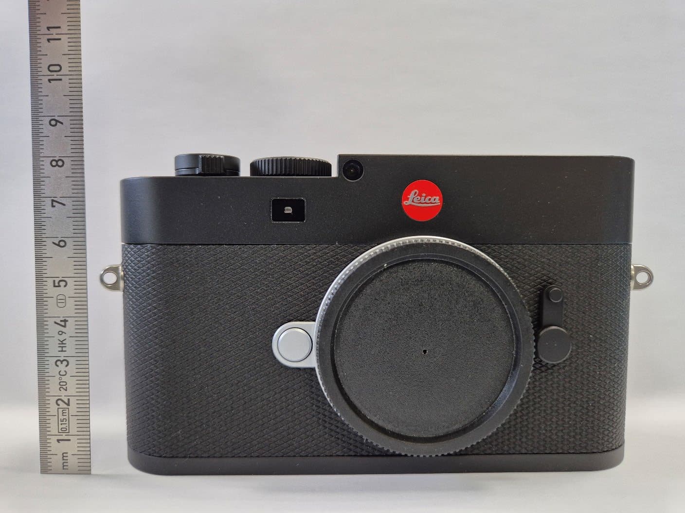
N5A4246
Nov 18, 2025Digital Camera
Equipment Class
NII - Unlicensed National Information Infrastructure TX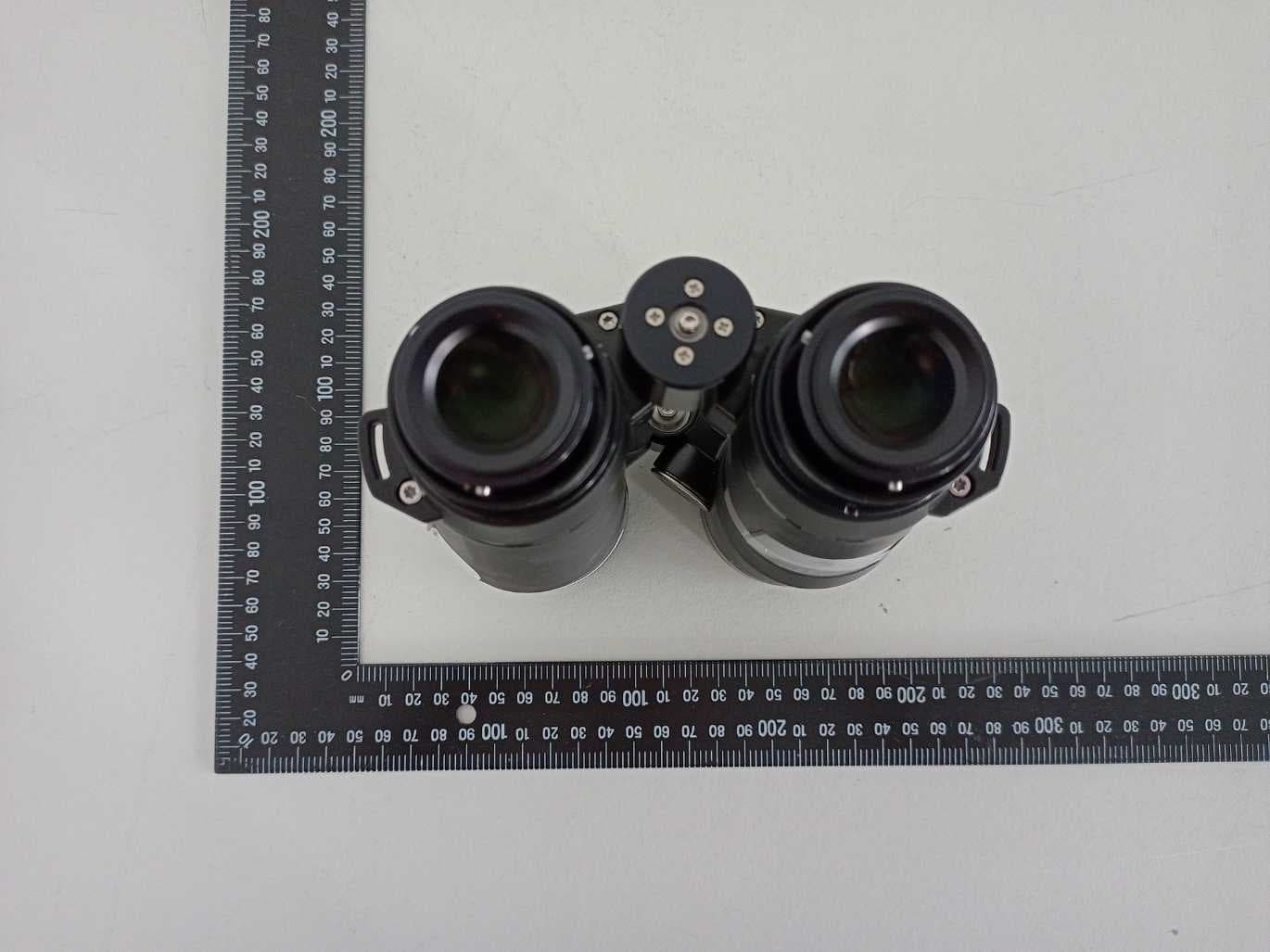
N5A6931
Jan 04, 2023Binocular with Laser Rangefinder
Equipment Class
DTS - Digital Transmission System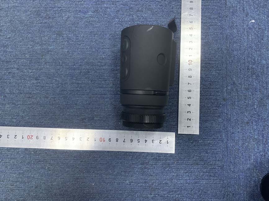
N5A1970
Oct 21, 2020Thermal Imaging Device
Equipment Class
DTS - Digital Transmission System
N5A6376
Jan 16, 2020Digital camera
Equipment Class
DTS - Digital Transmission System