N7TAC1100T2.4GHz FHSS Baby Unit
Angelcare Canada Inc.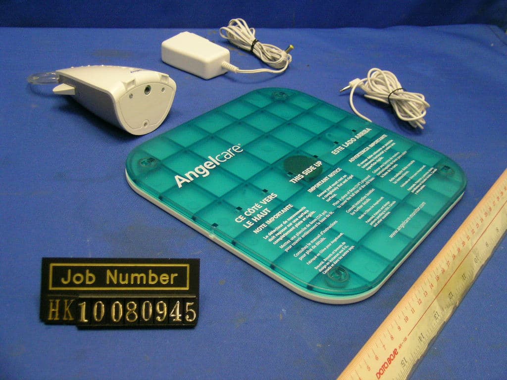
Click to zoom
Application Details
- Equipment Class
- DSS - Part 15 Spread Spectrum Transmitter
- Date of Grant
- Dec 22, 2010
- Application Purpose
- Original Equipment
- Date of Application
- Dec 22, 2010
- Equipment Note
- 2.4GHz FHSS Baby Unit
- Frequency Range
- 2404.12500000 - 2464.87500000
- Company
- Angelcare Canada Inc.
- Country
- Canada
Documents & Files
Document Text
Text extracted from the exhibit documents filed with the FCC. Open a document above to read the original.
Users Manual
Baby Monitor with video, sound & Movement Sensor Pad .......................................................................2 Moniteur pour bébés avec vidéo, sons et détecteur de mouvements ....................................................10 AC1100 Platinum edition 2 E N WARNINGS Failure to follow these warnings and the assembly instructions could result in serious injury or death. This product is designed to aid in the monitoring of your child. When using the monitor, you must still provide the supervision necessary for the continued safety of your child. Always be sure that both the transmitter and receiver are working properly and are within range of each other. This product is NOT a substitute for direct supervision of your baby.Check your baby’s activities at regular intervals. Monitoring of premature babies, or those considered to be at risk, should always be carried out under the supervision of a health professional. STRANGULATION HAZARD. Keep the adapter cords out of the reach of children. Do not use with extension cords. DO NOT place the Nursery Unit or its cord within your child’s reach. Do not put the Nursery Unit inside a crib or playard. Use ONLY with 110-120 volt AC electrical outlets. Allow for proper ventilation when units are in use. Do not cover the Nursery Unit or Parent Units with any object such as a blan- ket. Do not place it in a drawer or in any location which would muffle the sound or interfere with the normal flow of air. DO NOT immerse any part of the Nursery Unit, Parent Unit, Sen- sor Pad, adapters or docking station in water or any other liq- uid. Clean only with a dry cloth. DO NOT place unit near water and moisture. Do not use the Nursery Unit outdoors. Do not use the Nursery Unit near possi- ble wet areas, such as a bathtub, shower, wash basin, sink, laundry tub, swimming pool, wet basement, etc. Keep Nursery Unit away from heat sources, such as fireplaces, radiators, stoves, and TVs or other appliances. Heat can dam- age the case or electrical parts. WARNING: This product is not a toy. Do not use the Nursery Unit if: - The adapter cords or plugs have been damaged. - The unit has been exposed to liquids. - Unit has been dropped or is damaged. DO NOT OPEN the Nursery Unit, Parent Unit, Parent Unit base, Sensor Pad or adapters. No user-serviceable parts inside. Risk of electrical shock, fire or death. The antenna used for this transmitter must be installed to pro- vide a separation distance of at least 20 cm (7.9”) from all per- sons and must not be collocated or operating in conjunction with any other antenna or transmitter. IMPORTANT: You must use only rechargeable batteries in the Parents Unit. DO NOT use alkaline batteries or you will severely damage the unit. Charge the batteries for 16 hours prior to first use. Be sure to have the monitor in the OFF position during this period. Only use the AC adapters included with your monitor. DO NOT use these adapters with any other equipment. When unplugging the AC adapter from the Nursery Unit, be sure it is switched to the off position. If it isn’t, the unit will revert to battery mode if batteries are installed. You can use rechargeable batteries in the Nursery Unit, how- ever, they will not be recharged by plugging in the AC adapter. To recharge, remove the batteries and use an external charger. Always place both the Nursery Unit and Parents Unit on a flat surface in an upright position and allow for proper ventilation. Avoid damage to the Sensor Pad cord and to the adapter cords. Route cords so that they are not likely to be walked on or pinched by items placed on or against them. DO NOT use this monitor if the Sensor Pad cord and/or the adapters cords are damaged. Route Sensor Pad cord only below crib mattress and out of reach of children. Use ONLY AAA (LR03) rechargeable batteries and/or the AC adapters provided for the Parents Unit. During long periods of non-use remove all batteries from their compartments and unplug the AC adapters. This monitor uses public airwaves to transmit signals. The Par- ents Unit may pick up signals or interference from other nurs- ery monitors in your area. Your monitor may even be picked up by other households. To protect your privacy, make sure both units are turned off when not in use. When the monitor is in use, do not use a crib mobile or other crib accessories that may produce vibrations. Other sources of vibrations may include fans, washing machines, loud music, etc. These sources of vibration may interfere with the perform- ance of your Angelcare® monitor and the alarm will not sound if it continues to detect any movement other than your baby’s. Be sure all vibration sources are eliminated before using the monitor. You may experience false alarms for several reasons. The most common reason is the Nursery Unit has not been turned off after you have removed your baby from the crib. Another reason is if the Sensor Pad has not been placed under the mattress properly. Be sure the Sensor Pad is on a flat, firm surface with the printed side facing up. The sensitivity level may also need to be adjusted. Refer to the Movement Sensitivity Adjustment section. Always be sure to immediately check on baby whenever an alarm sounds. Your monitor can be used in any crib that is stationary and de- signed to safely hold a baby. If your crib has a spring or slat base you will need to place a piece of Masonite board under the Sen- sor Pad. This support must be at least 13 inches long on all four sides and 1/4 inch thick. Only use your Angelcare® monitor in a stationary sleeping environment such as a crib where the Sen- sor Pad can rest on a completely flat, firm surface. FCC WARNINGS Modifications not authorized by the manufacturer may void users authority to operate this device. NOTE: This equipment has been tested and found to comply with the limits for a Class B digital device, pursuant to Part 15 of the FCC Rules. These limits are designed to provide reasonable protection against ha…
Text truncated - open the document above for the full version.
External Photos
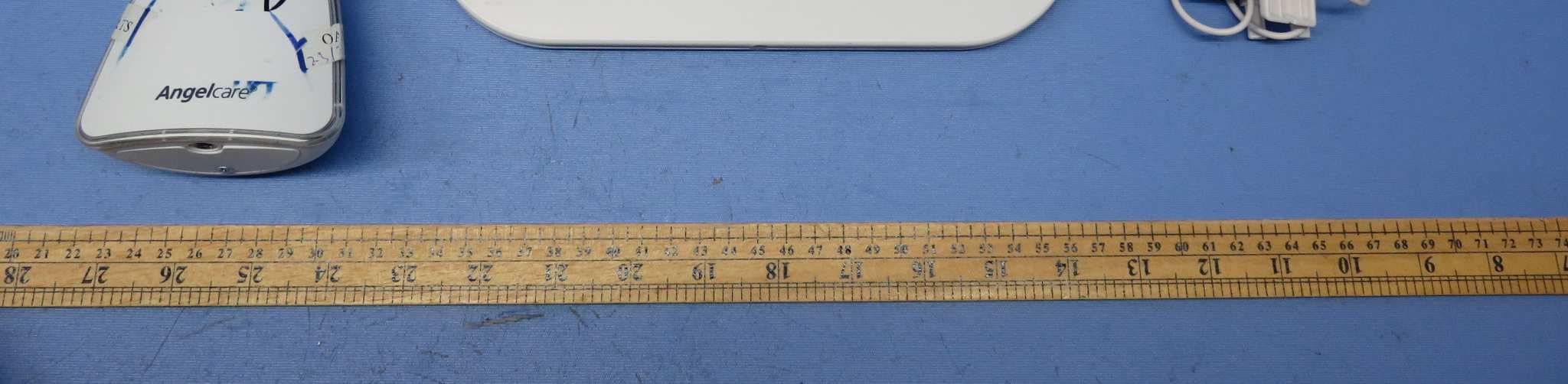
INTERTEK TESTING SERVICES External Photos FCC ID: N7TAC1100T IC: 5786A-AC1100T external photos - 1 of 2 INTERTEK TESTING SERVICES External Photos FCC ID: N7TAC1100T IC: 5786A-AC1100T external photos - 2 of 2
ID Label/Location Info
AC1100 Rev.3 12/14/2010 Engrave Engrave Pad Printing 3x1.5V AAA AAA 5mm7mm 30mm Use only power supplies and batteries listed on the user instructions Label-Battery/Adapter to be put inside the battery compartment 17.2mm x 1.3mm 16.5mm x 1.3mm 19.5mm x 1.4mm I C : 5 7 8 6 A-A C 1 1 0 0 T F C C I D : N 7TA C 1 1 0 0 T 500mA M O D E L : M O D E L : A C 1 1 0 0 A C 1 1 0 0
Internal Photos
INTERTEK TESTING SERVICES Internal photos FCC ID: N7TAC1100T IC: 5786A-AC1100T internal photos - 1 of 4 Baby Unit assembly Baby Unit Main PCB comp side (View 1) INTERTEK TESTING SERVICES Internal photos FCC ID: N7TAC1100T IC: 5786A-AC1100T internal photos - 2 of 4 Baby Unit Main PCB comp side (View 2) Baby Unit Main PCB comp side (View 3) INTERTEK TESTING SERVICES Internal photos FCC ID: N7TAC1100T IC: 5786A-AC1100T internal photos - 3 of 4 Baby Unit Main PCB solder side Baby Unit LED front side INTERTEK TESTING SERVICES Internal photos FCC ID: N7TAC1100T IC: 5786A-AC1100T internal photos - 4 of 4 Baby Unit LED rear side Baby Unit Oscillator PCB comp side
RF Exposure Info
INTERTEK TESTING SERVICES FCC ID: N7TAC1100T RF exposure info - 1 of 1 For Maximum Permissible Exposure (MPE) evaluation of the baby unit, the maximum power density at 20 cm from this mobile transmitter shall be less than the General Population / Uncontrolled MPE limit in OET Bulletin 65. For the baby unit of tested model of AC1100, the maximum field strength measured (FS) was 111.6 dBμV/m. The distance (D) between the antenna and the equipment under test (EUT) was 3 meters. And the maximum source-based time-averaging duty factor in one-parent unit operation is 50%. From these data, the exposed power density at a distance (R) of 20cm from the center of radiation of the antenna can be calculated according to OET Bulletin 65 as follow: The radiated power (EIRP) = (FS*D) 2 / 30 = 43.36 mW The radiated (EIRP) source-based time-averaging output power = (43.36 * 0.500) mW = 21.68 mW The power density at 20 cm from the antenna = EIRP / 4πR 2 = 0.0043 mW cm -2 In the frequency range of 1,500 - 100,000MHz, the MPE limit is 1.0 mWcm -2 for general population and uncontrolled exposure. As the measured power density at 20cm from the transmitter is lower than the MPE limit, the compliance to the MPE limit can be ensured by indicating the minimum 20cm separation between the transmitter's radiating structures and body of the user or nearby persons. The following RF exposure statement is proposed to be included in the user manual: “ FCC RF Radiation Exposure Statement Caution: To maintain compliance with the FCC’s RF exposure guidelines, place the baby unit at least 20cm from nearby persons.”
Test Report
INTERTEK TESTING SERVICES Maximum 20dB RF Bandwidth Plots FCC ID: N7TAC1100T IC: 5786A-AC1100T 20dB - 1 of 2 A0 Baby unit, Lowest channel Baby unit, Middle channel INTERTEK TESTING SERVICES Maximum 20dB RF Bandwidth Plots FCC ID: N7TAC1100T IC: 5786A-AC1100T 20dB - 2 of 2 A0 Baby unit, Highest channel
Test Report
INTERTEK TESTING SERVICES Average Channel Occupancy Time Plots FCC ID: N7TAC1100T IC: 5786A-AC1100T avetime - 1 of 2 Baby unit, traffic carrier (in a clear RF environment) Baby unit, traffic carrier (in a clear RF environment) INTERTEK TESTING SERVICES Average Channel Occupancy Time Plots FCC ID: N7TAC1100T IC: 5786A-AC1100T avetime - 2 of 2 Baby unit, traffic carrier, length of a single burst
Test Report
INTERTEK TESTING SERVICES Minimum Number Hopping Frequencies Plots FCC ID: N7TAC1100T IC: 5786A-AC1100T chno - 1 of 1 Baby unit, traffic carrier (in a RF interference environment)
Test Report
INTERTEK TESTING SERVICES Transmitter Duty Cycle Calculation and Measurement Plots FCC ID: N7TAC1100T IC: 5786A-AC1100T dcc - 1 of 1 Baby unit, traffic carrier
Test Report
INTERTEK TESTING SERVICES Minimum Hopping Channel Carrier Frequency Separation Plots FCC ID: N7TAC1100T IC: 5786A-AC1100T fsepa - 1 of 1 A0 Baby unit, between channel 9 and channel 10
Test Report
INTERTEK TESTING SERVICES Maximum Conducted Output Power at Antenna Terminals Plots FCC ID: N7TAC1100T IC: 5786A-AC1100T maxop - 1 of 2 A0 Baby unit, Lowest channel Baby unit, Middle channel INTERTEK TESTING SERVICES Maximum Conducted Output Power at Antenna Terminals Plots FCC ID: N7TAC1100T IC: 5786A-AC1100T maxop - 2 of 2 A0 Baby unit, Highest channel
Test Report
INTERTEK TESTING SERVICES Out Band Antenna Conducted Emission Plots FCC ID: N7TAC1100T IC: 5786A-AC1100T obantcon - 1 of 4 A0 Baby unit, Lowest channel, Plot 1 Baby unit, Lowest channel, Plot 2 INTERTEK TESTING SERVICES Out Band Antenna Conducted Emission Plots FCC ID: N7TAC1100T IC: 5786A-AC1100T obantcon - 2 of 4 A0 Baby unit, Middle channel, Plot 1 Baby unit, Middle channel, Plot 2 INTERTEK TESTING SERVICES Out Band Antenna Conducted Emission Plots FCC ID: N7TAC1100T IC: 5786A-AC1100T obantcon - 3 of 4 A0 Baby unit, Highest channel, Plot 1 Baby unit, Highest channel, Plot 2 INTERTEK TESTING SERVICES Out Band Antenna Conducted Emission Plots FCC ID: N7TAC1100T IC: 5786A-AC1100T obantcon - 4 of 4 A0 Baby unit, Bandedge plot, Plot 1 Baby unit, Bandedge plot, Plot 2
Test Report
- The test report only allows to be revised within the retention period unless further standard or the requirement was noticed. - This report is for the exclusive use of Intertek's Client and is provided pursuant to the agreement between Intertek and its Client. Intertek's responsibility and liability are limited to the terms and conditions of the agreement. Intertek assumes no liability to any party, other than to the Client in accordance with the agreement, for any loss, expense or damage occasioned by the use of this report. Only the Client is authorized to permit copying or distribution of this report and then only in its entirety. Any use of the Intertek name or one of its marks for the sale or advertisement of the tested material, product or service must first be approved in writing by Intertek. The observations and test results in this report are relevant only to the sample tested. This report by itself does not imply that the material, product, or service is or has ever been under an Intertek certification program. Intertek Testing Services Hong Kong Ltd. 2/F., Garment Centre, 576 Castle Peak Road, Kowloon, Hong Kong. Tel: (852) 2173 8888 Fax: (852) 2785 5487 Website: www.hk.intertek-etlsemko.com TEST REPORT Report Number: HK10080945-1 Application for Original Grant of 47 CFR Part 15 Certification New Family of RSS-210 Issue 8 Equipment Certification 2.4GHz Frequency Hopping Spread Spectrum Baby Unit FCC ID: N7TAC1100T IC: 5786A-AC1100T Prepared and Checked by: Approved by: Koo Wai Ip Nip Ming Fung, Melvin Lead Engineer Supervisor November 30, 2010 November 30, 2010 INTERTEK TESTING SERVICES Test Report Number: HK10080945-1 Page 1 of 39 FCC ID: N7TAC1100T IC: 5786A-AC1100T GENERAL INFORMATION Applicant Name: Angelcare Monitors Inc. Applicant Address: 3980, Rue St-Ambroise, Montreal, Quebec, H4C 2C7, Canada. FCC Specification Standard: FCC Part 15, October 1, 2009 Edition FCC ID: N7TAC1100T FCC Model(s): AC1100, AC1120 IC Specification Standard: RSS-210 Issue 8, December 2010 RSS-Gen Issue 3, December 2010 RSS-102 Issue 4, March 2010 IC: 5786A-AC1100T IC Model(s): AC1100, AC1120 Type of EUT: Spread Spectrum Transmitter Description of EUT: 2.4GHz Frequency Hopping Spread Spectrum Baby Unit Serial Number: N/A Sample Receipt Date: August 19, 2010 Date of Test: October 14-November 22, 2010 Report Date: November 30, 2010 Environmental Conditions: Temperature: +10 to 40°C Humidity: 10 to 90% INTERTEK TESTING SERVICES Test Report Number: HK10080945-1 Page 2 of 39 FCC ID: N7TAC1100T IC: 5786A-AC1100T Table of Contents 1.0 Test Results Summary & Statement of Compliance.......................................... 4 1.1 Summary of Test Results .................................................................................... 4 1.2 Statement of Compliance .................................................................................... 5 2.0 General Description............................................................................................. 7 2.1 Product Description ............................................................................................. 7 2.2 Test Methodology................................................................................................ 8 2.3 Test Facility......................................................................................................... 8 3.0 System Test Configuration................................................................................ 10 3.1 Justification ....................................................................................................... 10 3.2 EUT Exercising Software................................................................................... 11 3.3 Details of EUT and Description of Accessories.................................................. 12 3.4 Measurement Uncertainty ................................................................................. 12 3.5 Equipment Modification ..................................................................................... 12 4.0 Test Results........................................................................................................ 14 4.1 Maximum Conducted Output Power at Antenna Terminals ................................ 14 4.2 Maximum 20 dB RF Bandwidth......................................................................... 15 4.3 Minimum Number of Hopping Frequencies........................................................ 16 4.4 Minimum Hopping Channel Carrier Frequency Separation................................. 17 4.5 Average Channel Occupancy Time................................................................... 18 4.6 Out of Band Conducted Emissions .................................................................... 19 4.7 Field Strength Calculation.................................................................................. 20 4.8 Transmitter Radiated Emissions in Restricted Bands and Spurious Emissions... 21 4.8.1 Radiated Emission Configuration Photograph ................................................. 22 4.8.2 Radiated Emission Data ................................................................................. 22 4.8.3 Transmitter Duty Cycle Calculation ................................................................. 23 4.9 Radiated Emissions from Receiver .................................................................... 28 4.9.1 Radiated Emission Configuration Photograph ................................................. 28 4.9.2 Radiated Emission Data ................................................................................. 28 4.10 AC Power Line Conducted Emission ............................................................... 30 4.10.1 AC Power Line Conducted Emission Configuration Photograph.................... 30 4.10.2 AC Power Line Conducted Emission Data .................................................... 30 4.11 Radio Frequency Radiation Exposure...............................…
Text truncated - open the document above for the full version.
Test Setup Photos
INTERTEK TESTING SERVICES The Worst Case Configuration Photographs FCC ID: N7TAC1100T IC: 5786A-AC1100T config photos (radiated emission – baby unit) - 1 of 1 Radiated Emission – Baby Unit Front View Rear View INTERTEK TESTING SERVICES The Worst Case Configuration Photographs FCC ID: N7TAC1100T IC: 5786A-AC1100T config photos (conducted emission) - 1 of 2 Conducted Emission Front View Right Side View INTERTEK TESTING SERVICES The Worst Case Configuration Photographs FCC ID: N7TAC1100T IC: 5786A-AC1100T config photos (conducted emission) - 2 of 2 Conducted Emission Left Side View
Contact Information
Applicant
Mark Buckle(Technical Manager)
Technical Contact
Intertek Testing Services Hong Kong LtdMelvin Nip
[email protected]852-2173-8888
Flat D 5/F Garment Centre · Kowloon · Hong Kong
Non-Technical Contact
Intertek Testing Services Hong Kong LtdMelvin Nip
[email protected]852-2173-8888
Test Firm
Intertek Testing Services Hong Kong Ltd.Billy Chow
Technical Specifications
| # | Rule Parts | Frequency Range | Power Output |
|---|---|---|---|
| 1 | 15C | 2.40 GHz - 2.46 GHz | 42.00 mW |
Other Applications from Angelcare Canada Inc.
N7TAC1300T
Dec 02, 2015Video Baby Monitor - Baby Unit
Equipment Class
DSS - Part 15 Spread Spectrum Transmitter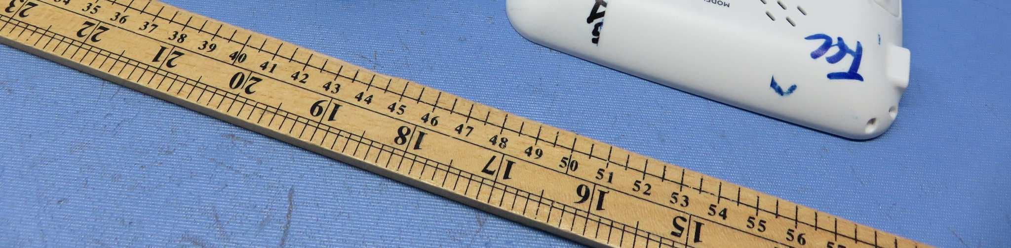
N7TAC1300R
Dec 02, 2015Video Baby Monitor - Parent Unit
Equipment Class
DSS - Part 15 Spread Spectrum Transmitter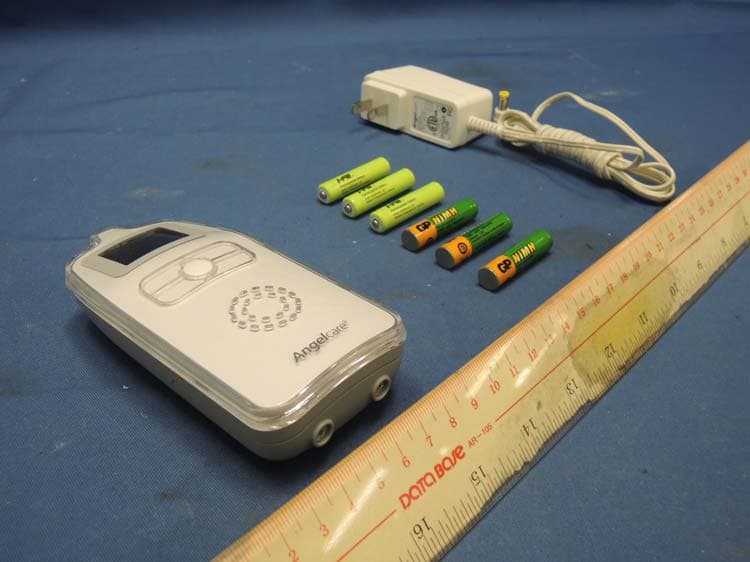
N7TAC423R
Jan 09, 2014900MHz Superheterodyne Receiver (Parent Unit)
Equipment Class
CYY - Communications Receiver used w/Pt 15 Transmitter
N7TAC423T
Jan 09, 2014900MHz Analog Modulation Baby Monitor (Baby Unit)
Equipment Class
DXX - Part 15 Low Power Communication Device Transmitter
N7TAC701T
Jan 01, 20141.9GHz DECT Baby Monitor - Baby Unit
Equipment Class
PUB - Part 15 Unlicensed PCS Base Station