N7TAC423T900MHz Analog Modulation Baby Monitor (Baby Unit)
Angelcare Canada Inc.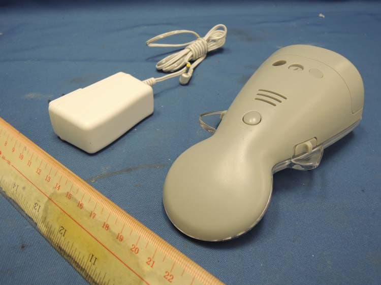
Click to zoom
Application Details
- Equipment Class
- DXX - Part 15 Low Power Communication Device Transmitter
- Date of Grant
- Jan 09, 2014
- Application Purpose
- Original Equipment
- Date of Application
- Jan 09, 2014
- Equipment Note
- 900MHz Analog Modulation Baby Monitor (Baby Unit)
- Frequency Range
- 926.00000000 - 927.60000000
- Company
- Angelcare Canada Inc.
- Country
- Canada
Documents & Files
Document Text
Text extracted from the exhibit documents filed with the FCC. Open a document above to read the original.
Users Manual
OWNER’S MANUAL SOUND MONITOR Model AC423 XX XX XX XX XX XX DE XX XX XX EN 2 FOR YOUR PEACE OF MIND SOUND MONITOR Model AC423 XX XX XX XX XX XX DE XX XX XX EN 2 TABLE OF CONTENT Warnings ..................................................................................................... 3 AC423 SETUP REQUIREMENTS........................................................7 STEP 1 - Charge Parent Unit ............................................................. 8 STEP 2 - Setup Nursery Unit.............................................................. 9 STEP 3 - Turn on your Monitor ........................................................10 STEP 4 - Test and get to know your Monitor ............................. 11 STEP 5 - Activate and deactivate additional functions ........14 Troubleshooting ......................................................................................16 Warranty ................................................................................................... 18 Technical specifications ......................................................................19 DEUTSCH................................................................................................. XX XX ............................................................................................................... XX OWNER’S MANUAL KEEP YOUR OWNER’S MANUAL FOR FUTURE REFERENCE. PLEASE READ THE WARNINGS AND INSTRUCTIONS CAREFULLY BEFORE ASSEMBLING & USING THE PRODUCT. FAILURE TO FOLLOW THE WARNINGS AND THE INSTRUCTIONS COULD RESULT IN SERIOUS INJURY OR DEATH OR DAMAGES TO THE PRODUCT. WARNING Adult assembly required. Keep small parts away from children when assembling. We, at Angelcare ® , stand behind all of our products. If you are not completely satisfied or have any questions, United States and Canada: please contact us at: [email protected] Other countries: please contact your local Distributor. 2 1. THIS PRODUCT CANNOT REPLACE RE- SPONSIBLE ADULT SUPERVISION. This product is designed to aid in the monitoring of your child. When using the monitor, you must still provide the supervision necessary for the continued safety of your child. Moni- toring of premature babies, or those consid- ered to be at risk, should always be carried out under the supervision of a health pro- fessional. This monitor is not intended to be used as a medical monitor. 2. STRANGULATION HAZARD. Children have STRANGLED in cords. Keep the Adapter cords out of the reach of children. DO NOT put the Nursery Unit inside a crib or play yard. Because of the seri- ous strangulation risk to infants and toddlers, parents and caregivers should never place the Nursery Unit within 3 feet (1 meter) of a crib. NEVER use extension cords with AC Adapters. ONLY use the AC Adapters provided. 3. When an AC Adapter is plugged into an electrical outlet, DO NOT touch the exposed end. 4. ALWAYS be sure that both the transmit- ter and receiver are working properly and are within range of each other. Test monitor be- fore first use, periodically and when changing location of the Nursery Unit. 5. ALWAYS be sure to immediately check on baby whenever an alarm sounds. 6. DO NOT use monitor near water (such as bath tub, sink, etc.). CAUTION RISK OF ELECTRIC SHOCK DO NOT OPEN DO NOT EXPOSE TO RAIN OR MOISTURE 7. Keep monitor AWAY from heat sources (such as stoves, radiators, etc.). 8. ALWAYS place both the Nursery Unit and Parent Unit on a flat surface in an upright position and allow for proper ventilation. DO NOT place on sofas, cushions, beds, etc. which may block ventilation. 9. This monitor uses public airwaves to trans- mit signals. The Parent Unit may pick up sig- nals or interference from other nursery moni- tors in your area. Your monitor may even be picked up by other households. To protect your privacy, make sure both units are turned OFF when not in use. If you experience in- terference, change the channel on both units. 10. This product is NOT a toy. DO NOT allow children to play with it. 11. This product contains small parts. Adult assembly required. Exercise care when un- packing and assembling the product and keep small parts away from children. 12. Use and store the monitor at a tempera- ture between 50°F (10°C) and 104°F (40°C). BATTERY WARNING 13. Use ONLY AAA RECHARGEABLE batter- ies for the Parent Unit. DO NOT mix old and new batteries. DO NOT mix alkaline, standard or rechargeable batteries. Insert batteries with correct polarity. DO NOT short-circuit supply terminals. ONLY use the recommend- ed batteries or equivalent (volts and size) and the correct adapter. Remove batteries when product is stored for long periods of time or when batteries are exhausted. Dispose ex- hausted batteries properly. DO NOT recharge non-rechargeable batteries. Rechargeable batteries are ONLY to be charged under adult supervision. Keep all batteries away from chil- dren. WARNING 3 E N IMPORTANT SAFETY INSTRUCTIONS 14.1 Read these instructions - All the safety instructions should be read before the prod- uct is operated. 14.2 Keep these instructions. The safety and operating instructions should be retained for future reference. 14.3 Heed all warnings – All warnings on the product and in the operating instructions should be adhered to. 14.4 Follow all instructions – All operating and use instructions should be followed. 14.5 Water and moisture - DO NOT use this apparatus near water. For example, near a bath tub, wash bowl, kitchen sink, laundry tub, in a wet environment or near a swim- ming pool and the like. Care should be taken so that objects DO NOT fall onto units and that liquids are not spilled into unit through its openings. 14.6 Cleaning - Disconnect all units before cleaning. DO NOT immerse in water any part of the Nursery Unit, Parent Unit. Clean only with dry cloth. DO NOT spray with cleaning products or solvents. 14.7 Ventilation - DO NOT block any ventila- tion openings. Allow for proper ventilation when units are in use. DO NOT cover the Nur…
Text truncated - open the document above for the full version.
Block Diagram
AC423_NU_BLK20131218.sch-1 - Wed Dec 18 11:59:31 2013 AC423-RFMOD-NU_US_BLK20131218.sch-1 - Wed Dec 18 12:05:37 2013
External Photos
INTERTEK TESTING SERVICES External Photos FCC ID: N7TAC423T IC: 5786A-AC423Texternal photos - 1 of 1 HK13110249 Job Number HK13110249 Job Number
ID Label/Location Info
AC423NU Rev. 3 12/11/2013 5mm7mm 30mm Use only power supplies and batteries listed on the user instructions Engrave AAA AAA Model: AC423 FCC ID: N7TAC423T IC: 5786A-AC423T Australia: Sensitivity H C 7.5V 16.6mm x 1.32mm 15.0mm x 1.32mm 17.5mm x 1.32mm FCC ID: N7TAC423T IC: 5786A-AC423T Australia: Model: AC423 11.5mm x 1.32mm
Internal Photos
INTERTEK TESTING SERVICES Internal photos FCC ID: N7TAC423T IC: 5786A-AC423T internal photos - 1 of 7 Baby Unit assembly Baby Unit Main PCB comp side (View 1) INTERTEK TESTING SERVICES Internal photos FCC ID: N7TAC423T IC: 5786A-AC423T internal photos - 2 of 7 Baby Unit Main PCB comp side (View 2) Baby Unit Main PCB solder side INTERTEK TESTING SERVICES Internal photos FCC ID: N7TAC423T IC: 5786A-AC423T internal photos - 3 of 7 Baby Unit MCU PCB front side Baby Unit MCU PCB rear side INTERTEK TESTING SERVICES Internal photos FCC ID: N7TAC423T IC: 5786A-AC423T internal photos - 4 of 7 Baby Unit AC Jack front side Baby Unit AC Jack rear side INTERTEK TESTING SERVICES Internal photos FCC ID: N7TAC423T IC: 5786A-AC423T internal photos - 5 of 7 Baby Unit Mic. front side Baby Unit Mic. rear side INTERTEK TESTING SERVICES Internal photos FCC ID: N7TAC423T IC: 5786A-AC423T internal photos - 6 of 7 Baby Unit Antenna Baby Unit Oscillator PCB comp side (View 1) INTERTEK TESTING SERVICES Internal photos FCC ID: N7TAC423T IC: 5786A-AC423T internal photos - 7 of 7 Baby Unit Oscillator PCB comp side (View 2) Baby Unit Oscillator PCB solder side
Operational Description
AC423 CIRCUIT DESCRIPTION I. AC423 Nursery Unit (Baby side) Main Circuit Description Category Number Name Location Description IC ACT B-47 MAIN PROCESSOR BU4 Handle all TX, and handle audio switching. IC FT24C02A EEPROM BU3 Memory of settings that run by BU4. IC LM324D MIC. AMP BU2-A, BU2-B Amplification of audio signal from microphone BMIC3 EX625P28K6221522 IC AIC1734-38PU DC REGULATOR BU1 Regulate a DC3.8V output to main circuit such as MCU and RF parts. LED 4LYG1D POWER LED BLED2 Green indication for power ON of nursery unit. LED HXHW5033 NIGHT LIGHT LED BLED1, 5, 6 ON for night light function. SWITCH SKA12D01NG4NA POWER SW. BSW1 Slide switch for power ON/OFF SWITCH SKA12D01NG4NA OUT OF RANGE SW. BSW2 Slide switch for out of range function ON/OFF. SWITCH TS-03-AL NIGHT LIGHT/ CHANNEL SW. BSW3 Function for paging Night light ON/OFF and channel select. TRAN- SISTOR 2N3904 SWITCH FOR NIGHT LIGHT BQ7 On/Off control for Night light RESONATOR 8MHz OSCILLATOR BX1 Oscillator for processor BU4 SOCKET DC050S0300 DC JACK SJ2 Connecting to DC 7.5V 500mA adaptor and pass DC source through BD2 , 1N4004 to regulator. BATTERIES (NOT INCLUDED) 4 X AAA SIZE BATTERY BATT1 Backup power source 6V to input of regulator through BD3, CUS04 VARIABLE RESISTOR 100KB MIC. SENS. ADJUST SVR1 Provide a device for user to adjust the input level of microphone (Mic. Sens.)to trigger RF transmission ON. (For VOX level adjust) TRAN- SISTOR 8550C SWITCH FOR MUTE BQ3 On/Off control for muting signal of microphone into RF module. TRAN- SISTOR 2N3906 TX POWER CONTROL BQ5 On/Off control of TX VCC for RF signal transmission. TRAN- SISTOR 2N3906 TX AMP. POWER BQ10 On/Off control of transmitter power Amp. RF signal transmission. RC FILTER NETWORK 30K,30K,3.3K,10K 0.1, 0.1, 0.1, 1 PILOT TONE SHAPER BR19,24 BR27,52 BC37,39 BC40,41 Filter made from RC network to shape out a sine wave like signal input into RF module from digital output of MCU BU4. SENSOR RESISTOR 10K TEMPERAT- URE SENSOR BTH1 Detect temperature change of NU surrounding. RF MODULE TO RF MODULE RF MODULE NU RF See details of NU RF module II. NU RF module Circuit Description Category Number Name Location Description IC GP214D DUAL FREQUENCY SYNTHESIZ- ER DU2 It operates to control of TX VCO loop. Serial data is sent from MCU via DATA, CLK and STB for channel selections. It generates TX fundamental frequencies, 926 to 927.6MHz . CRYSTAL 11.15MHz CRYSTAL OSCILLATOR DX1 Provide oscillation clock to PLL IC DU2. VARI- CAP DIODE 1SV305 FM MODULATOR DVD1 Frequency modulation (FM) is done for RF signal on audio and data signals which are fed from main PCB at MOD IN. RF TRAN- SISTOR C5066Y TRANSMIT OSCILLATOR DQ1 Provide RF frequencies, range 926 to 927.6MHz for RF transmitter. LC FILTER 0.015uH, 0.015uH, 3.3P BPF DL11, DL12, DC55 Band pass filter for RF transmitter signal to feed into RF transmitter amplifier. RF TRAN- SISTOR C5066Y TX AMP. DQ3 Amplification of RF transmitter signal into antenna for transmission. RF FILTER 927M TX_FILTER 927MHz DDF2 Filter for TX out RF signal which is fed into antenna for transmission. (range: 926 TO 927.6MHz) METAL ROD ROD ANTENNA TX ANTENNA DANT2 To transfer conducted power from RF module and radiate it in air for signal transmission to PU. Conducted power is -3dBm +/-2dB. TX antenna gain is 0dB. Note for use of frequency channel: 1. Channel 1 to 8 is used for normal use of sound transmission, data transmission (out of range and temperature reading) from NU to PU. 2. Channel 0 is a frequency channel that system is in channel select mode. When user select channel, the data is sent from NU to PU in the channel 0. 工作表1 AC423 FREQUENCY TABLE US/AU(FCC/AU APPROVAL) 1. NURSERY UNIT A. TRANSMISSION FREQUENCY CHANNELS CHANNELTX FREQUENCY TX FUNDAMENTAL NUMBER(MHz) (MHz) 0926.0926.0 1926.2926.2 2926.4926.4 3926.6926.6 4926.8926.8 5927.0927.0 6927.2927.2 7927.4927.4 8927.6927.6 頁 1
Schematics
423BSEN.sch-1 - Fri Nov 15 11:10:09 2013 423RFB.sch-1 - Fri Nov 15 11:11:45 2013
Test Report
Issuing Laboratory: Intertek Testing Services Hong Kong Limited Hong Kong Accreditation Service (HKAS) has accredited this laboratory under the Hong Kong Laboratory Accreditation Scheme (HOKLAS) for specific laboratory activities as listed in the HOKLAS directory of accredited laboratories. The results shown in this report were determined by this laboratory in accordance with its terms of accreditation. Test Report Number: 13110249HKG-001 Page 1 of 24 FCC ID: N7TAC423T IC: 5786A-AC423T Intertek Testing Services Hong Kong Ltd. 2/F., Garment Centre, 576 Castle Peak Road, Kowloon, Hong Kong. Tel: (852) 2173 8888 Fax: (852) 2785 5487 Website: www.hk.intertek-etlsemko.com GENERAL INFORMATION Angelcare Monitors Inc.: Angelcare Monitors Inc. Applicant Address: 9975, Av. De Catania, Local B, Brossard, Quebec J4Z 3V6 Canada FCC Specification Standard: FCC Part 15, October 1, 2012 Edition FCC ID: N7TAC423T FCC Model(s): AC423 IC Specification Standard: RSS-210 Issue 8, December 2010 RSS-Gen Issue 3, December 2010 IC: 5786A-AC423T IC Model(s): AC423 Type of EUT: Transceiver Description of EUT: 900MHz Analog Modulation Baby Monitor (Baby Unit) Serial Number: N/A Sample Receipt Date: November 5, 2013 Date of Test: November 11, 2013 to November 14, 2013 Report Date: December 16, 2013 Environmental Conditions: Temperature: +10 to 40°C Humidity: 10 to 90% Issuing Laboratory: Intertek Testing Services Hong Kong Limited Hong Kong Accreditation Service (HKAS) has accredited this laboratory under the Hong Kong Laboratory Accreditation Scheme (HOKLAS) for specific laboratory activities as listed in the HOKLAS directory of accredited laboratories. The results shown in this report were determined by this laboratory in accordance with its terms of accreditation. Test Report Number: 13110249HKG-001 Page 2 of 24 FCC ID: N7TAC423T IC: 5786A-AC423T Intertek Testing Services Hong Kong Ltd. 2/F., Garment Centre, 576 Castle Peak Road, Kowloon, Hong Kong. Tel: (852) 2173 8888 Fax: (852) 2785 5487 Website: www.hk.intertek-etlsemko.com Table of Contents 1.0 Test Results Summary & Statement of Compliance......................................... 4 1.1 Summary of Test Results ................................................................................... 4 1.2 Statement of Compliance ................................................................................... 4 2.0 General Description............................................................................................ 6 2.1 Product Description ............................................................................................ 6 2.2 Test Methodology............................................................................................... 6 2.3 Test Facility........................................................................................................ 6 3.0 System Test Configuration................................................................................. 8 3.1 Justification ........................................................................................................ 8 3.2 EUT Exercising Software.................................................................................... 9 3.3 Details of EUT and Description of Accessories................................................. 10 3.4 Measurement Uncertainty ................................................................................ 10 4.0 Test Results....................................................................................................... 12 4.1 Field Strength Calculation................................................................................. 12 4.2 Radiated Emissions.......................................................................................... 13 4.2.1 Radiated Emission Configuration Photograph ................................................ 13 4.2.2 Radiated Emission Data ................................................................................ 13 4.2.3 Transmitter Duty Cycle Calculation ................................................................ 17 4.3 Radiated Emission on the Bandedge................................................................ 18 4.4 AC Power Line Conducted Emission ................................................................ 21 4.4.1 AC Power Line Conducted Emission Configuration Photograph..................... 21 4.4.2 AC Power Line Conducted Emission Data ..................................................... 21 5.0 Equipment List................................................................................................. 24 Issuing Laboratory: Intertek Testing Services Hong Kong Limited Hong Kong Accreditation Service (HKAS) has accredited this laboratory under the Hong Kong Laboratory Accreditation Scheme (HOKLAS) for specific laboratory activities as listed in the HOKLAS directory of accredited laboratories. The results shown in this report were determined by this laboratory in accordance with its terms of accreditation. Test Report Number: 13110249HKG-001 Page 3 of 24 FCC ID: N7TAC423T IC: 5786A-AC423T Intertek Testing Services Hong Kong Ltd. 2/F., Garment Centre, 576 Castle Peak Road, Kowloon, Hong Kong. Tel: (852) 2173 8888 Fax: (852) 2785 5487 Website: www.hk.intertek-etlsemko.com EXHIBIT 1 TEST RESULTS SUMMARY & STATEMENT OF COMPLIANCE Issuing Laboratory: Intertek Testing Services Hong Kong Limited Hong Kong Accreditation Service (HKAS) has accredited this laboratory under the Hong Kong Laboratory Accreditation Scheme (HOKLAS) for specific laboratory activities as listed in the HOKLAS directory of accredited laboratories. The results shown in this report were determined by this laboratory in accordance with its terms of accreditation. Test Report Number: 13110249HKG-001 Page 4 of 24 FCC ID: N7TAC423T IC: 5786A-AC423T Intertek Testing Services Hong Kong Ltd. 2/F., Garment Centre, 576 Castle Peak Road, Kowloon, Hong Kong. Tel: (852) 2173 8888 Fax: (852) 2785 5487 Website: ww…
Text truncated - open the document above for the full version.
Test Setup Photos
INTERTEK TESTING SERVICES The Worst Case Configuration Photographs - Mode: Transmission FCC ID: N7TAC423T IC: 5786A-AC423T config photos (radiated emission) - 1 of 1 Radiated Emission Front View Rear View INTERTEK TESTING SERVICES The Worst Case Configuration Photographs - Mode: Talk with Night Light FCC ID: N7TAC423T IC: 5786A-AC423T config photos (conducted emission) - 1 of 2 Conducted Emission Front View Right Side View INTERTEK TESTING SERVICES The Worst Case Configuration Photographs - Mode: Talk with Night Light FCC ID: N7TAC423T IC: 5786A-AC423T config photos (conducted emission) - 2 of 2 Conducted Emission Left Side View
Contact Information
Applicant
Mark Buckle(Technical Manager)
Technical Contact
Intertek Testing Services Hong Kong Ltd.Melvin Nip
[email protected]852-2173-8888
Flat D, 5/F., Garment Centre · Kowloon · Hong Kong
Non-Technical Contact
Intertek Testing Services Hong Kong Ltd.Melvin Nip
[email protected]852-2173-8888
Test Firm
Intertek Testing Services Hong Kong Ltd.Billy Chow
Technical Specifications
| # | Rule Parts | Frequency Range | Power Output |
|---|---|---|---|
| 1 | 15C | 926 MHz - 927.6 MHz | - |
Other Applications from Angelcare Canada Inc.
N7TAC1300T
Dec 02, 2015Video Baby Monitor - Baby Unit
Equipment Class
DSS - Part 15 Spread Spectrum Transmitter
N7TAC1300R
Dec 02, 2015Video Baby Monitor - Parent Unit
Equipment Class
DSS - Part 15 Spread Spectrum Transmitter
N7TAC423R
Jan 09, 2014900MHz Superheterodyne Receiver (Parent Unit)
Equipment Class
CYY - Communications Receiver used w/Pt 15 Transmitter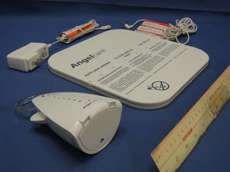
N7TAC701T
Jan 01, 20141.9GHz DECT Baby Monitor - Baby Unit
Equipment Class
PUB - Part 15 Unlicensed PCS Base Station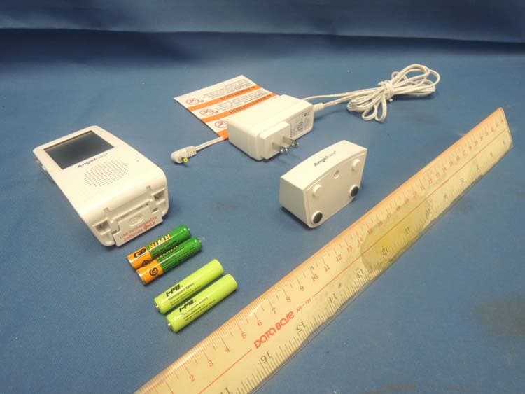
N7TAC701R
Jan 01, 20141.9GHz DECT Baby Monitor - Parent Unit
Equipment Class
PUT - Part 15 Unlicensed PCS portable Tx worn on body