N7TAC401-T900MHz Transceiver
Angelcare Canada Inc.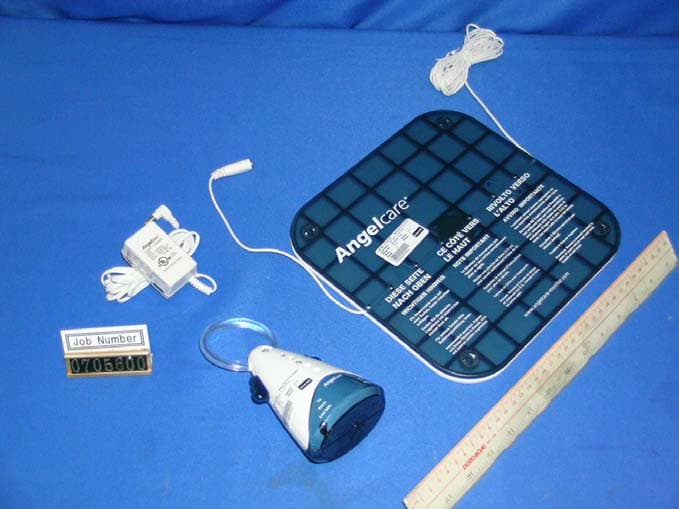
Click to zoom
Application Details
- Equipment Class
- DXT - Part 15 Low Power Transceiver, Rx Verified
- Date of Grant
- Jun 19, 2007
- Application Purpose
- Original Equipment
- Date of Application
- Jun 19, 2007
- Equipment Note
- 900MHz Transceiver
- Frequency Range
- 926.00000000 - 927.60000000
- Company
- Angelcare Canada Inc.
- Country
- Canada
Documents & Files
Document Text
Text extracted from the exhibit documents filed with the FCC. Open a document above to read the original.
Users Manual
AC401 Rechargeable Movement & Sound Monitor Moniteur de mouvements et de son rechargeable AC401 manuel ENG V4.qxd 4/25/07 3:39 PM Page 1 2 TABLE OF CONTENT Your Angelcare® Monitor components and special features . . . . . . . . . . . . . . . . . . . . . . . . . . . . . . . . . . . . . . . . .2 How to operate your Angelcare ® Monitor . . . . . . . . . . . . . . . . . . . . . . . . . . . . . . . . . . . . . . . . . . . . . . . . . . . . . . .3 Testing your Angelcare ® Monitor . . . . . . . . . . . . . . . . . . . . . . . . . . . . . . . . . . . . . . . . . . . . . . . . . . . . . . . . . . . . . .5 Warnings . . . . . . . . . . . . . . . . . . . . . . . . . . . . . . . . . . . . . . . . . . . . . . . . . . . . . . . . . . . . . . . . . . . . . . . . . . . . . . .5 Maintenance of your Angelcare ® Monitor . . . . . . . . . . . . . . . . . . . . . . . . . . . . . . . . . . . . . . . . . . . . . . . . . . . . . . .6 Troubleshooting . . . . . . . . . . . . . . . . . . . . . . . . . . . . . . . . . . . . . . . . . . . . . . . . . . . . . . . . . . . . . . . . . . . . . . . . . .7 Warranty . . . . . . . . . . . . . . . . . . . . . . . . . . . . . . . . . . . . . . . . . . . . . . . . . . . . . . . . . . . . . . . . . . . . . . . . . . . . . . . .8 Distributors . . . . . . . . . . . . . . . . . . . . . . . . . . . . . . . . . . . . . . . . . . . . . . . . . . . . . . . . . . . . . . . . . . . . . . . . . . . . .16 2 (Two) 7.5 volt AC adapters RECHARGEABLE PARENTS UNIT (RECEIVER) & CHARGER NURSERY UNIT (TRANSMITTER) YOUR ANGELCARE ® MONITOR COMPONENTS FEATURES YOU WILL ALSO NEED : 4AAA non-rechargeable batteries(not included) as back up for the nursery unit in case of power failure. Practical soothing night light. Nursery room temperature display on the parents unit. Convenient belt clip. Choice of voice activated or continuous sound reception. 4 AAA RECHARGEABLE BATTERIES FOR PARENTS UNIT SENSOR PAD(S) 1 or 2 ALARM AND WARNING Your Angelcare © monitor will let you know if no movement is detected by alarms, vibration and visual effects. The practical portable parents unit keeps you informed at all time. An alarm is triggered on the nursery unit and the flashing pendulum green light stops flashing. The par ents unit lights up and the nurser y unit icon appears. Vibration on the parents unit. An alar mis triggered on the par ents unit. AC401 manuel ENG V4.qxd 4/25/07 3:39 PM Page 2 3 HOW TO OPERATE YOUR ANGELCARE ® MONITOR Charger ada pter socket STEP 1 Power ON/OFF Parents unit pa ger Sound volume UP/DOWN • Connect the long sensor pad cord into the nursery unit. • Insert 4 AAA regular batteries (not included) into nursery unit (for battery backup in case of power failure). • Connect AC adapter to nursery unit and plug adapter into an electrical outlet in the baby’s room. • After both units are properly installed you may adjust the sensor pad sensitivity level (if necessary). • Once the parents unit is fully charged (after 15 hours) turn the unit ON and turn the nursery unit ON. If the parents unit is turned ON and the nursery unit is OFF, the parents unit will start beeping after 1 minutes. After 4 seconds, the unit will shuts itself off. • The different available options are programmable but you can use the units right away, with the following factory settings : - Sound, movement and tic activated - Out of range notifica tion OFF - Voice activated ON - Temperature display ON, Room temperature control OFF - P arents unit alarm ON, vibration OFF - Speaker volume at 3 - Voice sensitivity at 2 • T o avoid feedback (whistling sound), keep both units at least 3 meters apart (10 feet). • You can adjust the sound volume with the arrow buttons. • T o turn the night light ON, move the right wing button UP. •Insert 4 AAA NIMH rechargeable batteries (included) into parents unit. NEVER use regular alkaline batteries. •Connect AC adapter to parents unit charger and plug adapter into an electrical outlet. Let charge for 15 continuous hours before using the monitor for the first time. Charger ada pter socket Sensor pad cord socket Adapter socket Sensor pad sensitivity dial I sensor pad2 sensor pads POSITION OF SENSOR PAD UNDER MATTRESS Crib centerCrib center • Position the sensor pad as shown above. Make sure the printed side faces up. Do place any bedding between the mattress and the sensor pad. •Secure the sensor pad cord to crib using a tie wrap.Run the cord on the floor to ensure it is out of the baby’s reach. • The sensor pad must rest on a completely flat and rigid surface. Place a 6mm (1/4”) plywood to cover the full size of the crib base. Make sure the sensor pad’s cord passes underneath the mattress as shown above. Keep at least 38 cm ( 15 inches) a part Sensor Pad(s) 1 or 2 INSTALLATION OF THE SENSOR PAD UNDER THE MATTRESS STEP 2 INSTALLATION OF THE NURSERY UNIT Battery compartment STEP 3 INSTALLATION OF THE PARENTS UNIT Battery compartment STEP 4 HOW YO USE YOUR ANGELCARE© MONITOR P o wer ON/OFF Movement capture indicator (Flashing) ON/ OFF Night light button Power ON indicator Lo w ba tter y indicator Microphone Speaker AC401 manuel ENG V4.qxd 4/25/07 3:39 PM Page 3 4 • All programmable functions of your Angelcare© monitor are available through the MENU button. • When the desired option appears on your screen, press SELECT. The different choices of each option is available through the UP and DOWN arrows. • AT ANY TIME after programming a function, if you wish to exit the menu selection, press on the EXIT button. If you wish to perform additional programming press MENU to view the next option. STEP 5 SCREEN AND BUTTONS STEP 6 TICS, SOUNDS AND MOVEMENTS STEP 7 OUT OF RANGE INDICATOR STEP 8 MICROPHONE SENSITIVITY Your Angelcare© monitor gives you the possibility to chose what you wish to monitor. -The “TIC”is a sound that tells you that your sensor pad is detecting movements. - The “SOUND” function is activated by the baby’s voice or continuous or is transmitted continuously (see STEP 8) - The “MOVEMENT” f…
Text truncated - open the document above for the full version.
Block Diagram
BD512`OVS`CML/tdi.2!.!Xfe!Bqs!36!28;1:;44!3118 BD512.SGNPE.OVS`VT`CML/tdi.2!.!Xfe!Bqs!36!27;62;13!3118
External Photos
INTERTEK TESTING SERVICES External Photos FCC ID: N7TAC401-T external photos - 1 of 1 External Photo - Front External Photo - Rear
ID Label/Location Info
AC401NurseryRev.004/30/2007 Sensitivity 7.5V Sensor pad Model # AC401
Internal Photos
INTERTEK TESTING SERVICES Internal photos FCC ID: N7TAC401-T internal photos - 1 of 6 Internal Photo - 1 Internal Photo - 2 INTERTEK TESTING SERVICES Internal photos FCC ID: N7TAC401-T internal photos - 2 of 6 Internal Photo - 3 Internal Photo - 4 INTERTEK TESTING SERVICES Internal photos FCC ID: N7TAC401-T internal photos - 3 of 6 Internal Photo - 5 Internal Photo - 6 INTERTEK TESTING SERVICES Internal photos FCC ID: N7TAC401-T internal photos - 4 of 6 Internal Photo - 7 Internal Photo - 8 INTERTEK TESTING SERVICES Internal photos FCC ID: N7TAC401-T internal photos - 5 of 6 Internal Photo - 9 Internal Photo - 10 INTERTEK TESTING SERVICES Internal photos FCC ID: N7TAC401-T internal photos - 6 of 6 Internal Photo - 11 Internal Photo - 11
Operational Description
CIRCUIT DESCRIPTION OF AC401 A. BABY UNIT 1. POWER SUPPLY DC 7.5V from AC adapter or 6V battery is input and they are input to BU1 regulator to provide main DC supply to the rest of circuit. (4 pieces of AAA size alkaline batteries can be used to power up the unit instead of using AC adapter.) 2. POWER AND NIGHTLIGHT SWITCHES BSW1 is built to control power on/off of the unit. BSW2 is built to turn on and off the night light (LED at the eye of angel). 3. MOVEMENT SENSOR PAD SENSITIVITY ADJUST Movement vibration is input through SJ1 and the signal is filtered by active filter formed by SU1-A and SU1-B op-amps. The filtered signal is input into pin 26 of CPU BU4 through SCN1-2 and normal movement display is shown by BLED2 with tic sound from BBUZ1 which is located on the microphone PCB. If movement signal is found abnormal or no vibration detected, alarm sound will alert from BBUZ1. In addition, data will be sent to parent side for alerting alarm. SVR1 is used to adjust a level what user wants for the application. 4. PAGE AND REGISTRATION BUTTON Switch BSW3 is used as: a. Press and release for paging parent unit. b. Press and hold for 2 seconds for registration with parent unit in order to link up data communication. 5. SOUND DETECT AND TRANSMISSION Microphone BMIC1 collects surrounding sound and the signal is enlarged by BU2-A and BU2-B. BU2-B output is also used for detecting level of input sound if it is large enough to turn on transmission to parent unit. BU4 CPU turns on audio MUTE switching transistor BQ3 for audio passing into RF module. RF TX power is turned ON by switching transistors, BQ5 for TXVCC and BQ10 for VPA (power amplifier DC) from BU4 control. 6. PILOT TONE SHAPER Pilot tone shaper is formed by BR71,19,24,27 and BC37,39,40,41 which filters the signal from CPU and forms the pilot tone into RF module. 7. DATA SHAPER BQ68, BQ9 form a data shaper which regulates the data transmitted from parent unit, such as commands to change operation modes and channel selection. 8. BATTERY DETECT AND LOW ALERT While using alkaline battery, battery level is detected by voltage level detected at junction of BR43 and BR55. If battery is detected low, BLED3 will flash to alert user. 9. RF MODULE OPERATION I. TX part Audio or data signal is input into the RF module and modulates the RF signal through DVD1. DU2 PLL is controlled by CPU BU4 and drives the TXVCO DQ1 in which transmission frequency is adjusted by tuning DVC1. Transmission frequency (926-927.6MHz) is amplified at amplifiers DQ2 and DQ3 and then filtered by DDF2, dielectric filter (927MHz). RF signal (926-927.6MHz) is radiated out at antenna DANT2 which is matched with DL3 and DC28. DANT2 is a rod antenna which is fixed on PCB and without gain. II. RX part Radiated signal (2401.7-2402.9MHz) from parent is collected by antenna DANT1 and passed through matching components DC48 and DL8 to dielectric filter DDF1 (2403MHz). The received signal is amplified by DQ4 amplifier. Amplified received signal is mixed with VCO frequency (2391-2392.2MHz) from DQ5 at DQ7 mixer. The VCO frequency from DQ7 is doubled from PLL IC DU2 which generates the fundamental VCO frequency (1195.5-1196.1MHz). The output of DQ5, 10.7MHz, passes through first 10.7MHz filter DCF2 and amplified by DQ6 and then passes to 10.7MHz filter DCF1. Filtered 10.7MHz signal is fed into the input of IF IC DU1. Filtered 10.7MHz is mixed with 11.15MHz (DX1 oscillation) inside DU1 and a second IF 450kHz is generated. The 450kHz IF is output from pin 3 of DU1 and then filtered by components DL5,6 and DC69-71, 450kHz filter and then through DC67 back to DU1 pin 5 into internal demodulator. The received data is finally recovered from demodulator of DU1 which uses conventional quadrature detector contributed by HIFT1. The demodulated audio signal then passes into base band PCB at AF OUT pin (pin 1) of the module. B. PARENT UNIT 1. POWER SUPPLY ! DC 7.5V from Adapter or 4 X AAA size battery !is input to U3 regulator. U3 outputs 3.8V DC which gives supply to other parts of circuit of the unit. 2. POWER SWITCH K5 is used as power on/off control of the unit. 3. DATA SHAPER Q7, Q8 form a data shaper which regulate the data transmitted from base, such as channel selection. 4. DATA TRANSMISSION Data command to nursery is sourced from pin 61 of U1. The data signal is fed into RF module through R88 and R7. The RF module transmission power is supplied from main PCB through turning on switching transistors Q13 and Q14. AC401 FREQUENCY TABLE 1. Baby Unit A. Transmission Frequency Channels CHANNEL NUMBER TX FREQUENCY (MHz) 0 926.0 1 926.2 2 926.4 3 926.6 4 926.8 5 927.0 6 927.2 7 927.4 8 927.6 B. Receiving Frequency Channels CHANNEL NUMBER TX FREQUENCY (MHz) 0 2401.7 1 2402.3 2 2402.9
Schematics
512CN/tdi.2!.!Npo!Nbs!37!21;45;61!3118 512CTFO/TDI.2!.!Npo!Nbs!37!21;53;31!3118 512SGC`FV/tdi.2!.!Npo!Nbs!37!21;64;2:!3118
Test Report
- The evaluation data of the report will be kept for 3 years from the date of issuance. - This report is for the exclusive use of Intertek's Client and is provided pursuant to the agreement between Intertek and its Client. Intertek's responsibility and liability are limited to the terms and conditions of the agreement. Intertek assumes no liability to any party, other than to the Client in accordance with the agreement, for any loss, expense or damage occasioned by the use of this report. Only the Client is authorized to permit copying or distribution of this report and then only in its entirety. Any use of the Intertek name or one of its marks for the sale or advertisement of the tested material, product or service must first be approved in writing by Intertek. The observations and test results in this report are relevant only to the sample tested. This report by itself does not imply that the material, product, or service is or has ever been under an Intertek certification program. Intertek Testing Services Hong Kong Ltd. 2/F., Garment Centre, 576 Castle Peak Road, Kowloon, Hong Kong. Tel: (852) 2173 8888 Fax: (852) 2785 5487 Website: www.hk.intertek-etlsemko.com Angelcare Monitors Inc. Application For Certification 900MHz Transceiver (FCC ID: N7TAC401-T) 07056001 KL/ ac May 29, 2007 INTERTEK TESTING SERVICES FCC ID: N7TAC401-T i LIST OF EXHIBITS INTRODUCTION EXHIBIT 1: General Description EXHIBIT 2: System Test Configuration EXHIBIT 3: Emission Results EXHIBIT 4: Equipment Photographs EXHIBIT 5: Product Labelling EXHIBIT 6: Technical Specifications EXHIBIT 7: Instruction Manual INTERTEK TESTING SERVICES FCC ID: N7TAC401-T ii MEASUREMENT/TECHNICAL REPORT Angelcare Monitors Inc. - Model: AC401 FCC ID: N7TAC401-T This report concerns (check one:) Original Grant X Class II Change Equipment Type : DXT - Pt 15 Low Pwr Transceiver, Rx Verified Deferred grant requested per 47 CFR 0.457(d)(1)(ii)? Yes No X If yes, defer until : date Company Name agrees to notify the Commission by: date of the intended date of announcement of the product so that the grant can be issued on that date. Transition Rules Request per 15.37 ? Yes No X If no, assumed Part 15, Subpart C for intentional radiator - the new 47 CFR [04-05-05 Edition] Provision. Report prepared by: Lam Chun Cheong, Kenneth Intertek Testing Services Hong Kong Ltd. 2/F., Garment Centre, 576 Castle Peak Road, Kowloon, Hong Kong. Phone : 852-2173-8474 Fax: 852-2741-1693 INTERTEK TESTING SERVICES FCC ID: N7TAC401-T iii Table of Contents 1.0 General Description................................................................................................. 2 1.1 Product Description ................................................................................................. 2 1.2 Related Submittal(s) Grants .................................................................................... 3 1.3 Test Methodology.................................................................................................... 3 1.4 Test Facility............................................................................................................. 3 2.0 System Test Configuration...................................................................................... 5 2.1 Justification ............................................................................................................. 5 2.2 EUT Exercising Software......................................................................................... 5 2.3 Support Equipment List and Description .................................................................. 6 2.4 Measurement Uncertainty ....................................................................................... 7 2.5 Equipment Modification ........................................................................................... 7 3.0 Emission Results..................................................................................................... 9 3.1 Field Strength Calculation...................................................................................... 10 3.2 Radiated Emission Configuration Photograph........................................................ 11 3.3 Radiated Emission Data ........................................................................................ 12 3.4 Radiated Emission on the Bandedge..................................................................... 15 3.5 Line Conducted Configuration Photograph ............................................................ 16 3.6 Line Conducted Emission Data.............................................................................. 17 4.0 Equipment Photographs........................................................................................ 20 5.0 Product Labelling................................................................................................... 22 6.0 Technical Specifications........................................................................................ 24 7.0 Instruction Manual................................................................................................. 26 INTERTEK TESTING SERVICES FCC ID: N7TAC401-T iv List of attached file Exhibit type File Description filename Test Report Test Report report.pdf Operation Description Technical Description descri.pdf Test Setup Photo Radiated & Conducted Emission config photos.doc Test Report Emission Plot emission.pdf Test Report Conducted Emission Test Result conduct.pdf External Photo External Photo external photos.doc Internal Photo Internal Photo internal photos.doc Block Diagram Block Diagram block.pdf Schematics Circuit Diagram circuit.pdf ID Label/Location Label Artwork and Location label.pdf User Manual User Manual manual.pdf INTERTEK TESTING SERVICES FCC ID: N7TAC401-T 1 EXHIBIT 1 GENERAL DESCRIPTION INTERTEK TESTING SERVICES FCC ID: N7TAC401-T 2 1.0 General Description 1.1 Product Description The Equipment Under Test (EUT) is a 900MHz transceiver (Bab…
Text truncated - open the document above for the full version.
Test Report
INTERTEK TESTING SERVICES Radiated Emission on the Bandedge Plots FCC ID: N7TAC401-T emission - 1 of 1 Plot B1A Plot B1B
Test Report
Report No.: 07056001 TX mode AC mains ‘L’ Ctrl No.: N/A PAGE 1 Tested By:Hong, Report No.:07056001 Scan Settings (1 Range) |--------- Frequencies -----------||----------- Receiver Settings ------------| Start Stop Step IF BW Detector M-Time Atten Preamp OpRge 150k 30M 5k 10k PK+AV 10ms AUTO LN OFF 60dB Final Measurement: x QP / + AV Meas Time: 1 s Subranges: 16 Acc Margin: 20dB Transducer No. Start Stop Name 2 1 9k 30M EW0700 12 9k 30M EW0090 0 10 20 30 40 50 60 70 80 90 dBuV 100 0.15 MHz 30 110 F15Q F15A Report No.: 07056001 TX mode AC mains ‘L’ Ctrl No.: N/A Tested By:Hong, Report No.:07056001 Scan Settings (1 Range) |--------- Frequencies -----------||----------- Receiver Settings ------------| Start Stop Step IF BW Detector M-Time Atten Preamp OpRge 150k 30M 5k 10k PK+AV 10ms AUTO LN OFF 60dB Final Measurement Results: Frequency QP Level QP Limit MHz dBuV dBuV no Results Frequency AV Level AV Limit MHz dBuV dBuV 24.14000 38.2 50.0 * limit exceeded
Test Setup Photos
INTERTEK TESTING SERVICES The Worst Case Configuration Photographs FCC ID: N7TAC401-T config photos (radiated emission) - 1 of 1 Radiated Emission Front View Rear View INTERTEK TESTING SERVICES The Worst Case Configuration Photographs FCC ID: N7TAC401-T config photos (conducted emission) - 1 of 2 Conducted Emission Front View Right Side View INTERTEK TESTING SERVICES The Worst Case Configuration Photographs FCC ID: N7TAC401-T config photos (conducted emission) - 2 of 2 Conducted Emission Left Side View
Contact Information
Applicant
Mark Buckle(Technical Manager)
Technical Contact
Intertek Testing Services Hong Kong Ltd.Kenneth Lam
[email protected](852) 2173 8474
Flat D, 5/F., Garment Centre, · Kowloon · Hong Kong
Non-Technical Contact
Intertek Testing Services Hong Kong Ltd.Kenneth Lam
[email protected](852) 2173 8474
Test Firm
Intertek Testing Services Hong KongBilly Chow
Technical Specifications
| # | Rule Parts | Frequency Range | Power Output |
|---|---|---|---|
| 1 | 15C | 926 MHz - 927.6 MHz | - |
Other Applications from Angelcare Canada Inc.
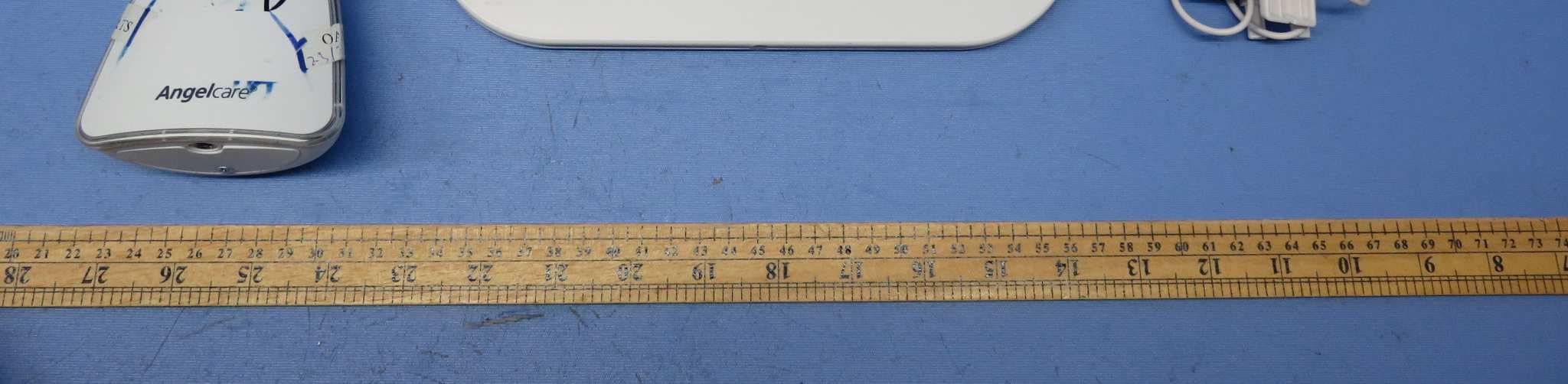
N7TAC1300T
Dec 02, 2015Video Baby Monitor - Baby Unit
Equipment Class
DSS - Part 15 Spread Spectrum Transmitter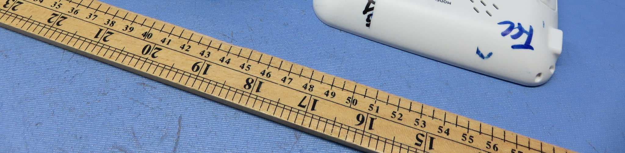
N7TAC1300R
Dec 02, 2015Video Baby Monitor - Parent Unit
Equipment Class
DSS - Part 15 Spread Spectrum Transmitter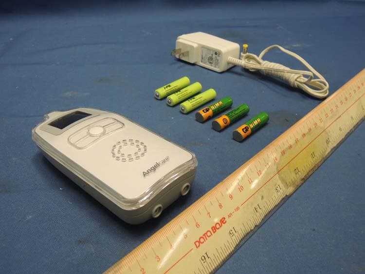
N7TAC423R
Jan 09, 2014900MHz Superheterodyne Receiver (Parent Unit)
Equipment Class
CYY - Communications Receiver used w/Pt 15 Transmitter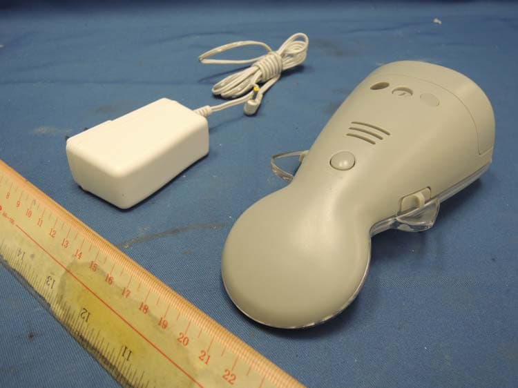
N7TAC423T
Jan 09, 2014900MHz Analog Modulation Baby Monitor (Baby Unit)
Equipment Class
DXX - Part 15 Low Power Communication Device Transmitter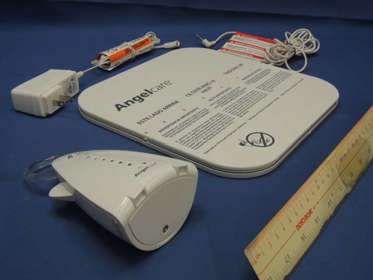
N7TAC701T
Jan 01, 20141.9GHz DECT Baby Monitor - Baby Unit
Equipment Class
PUB - Part 15 Unlicensed PCS Base Station