N7TAC420-RSuperheterodyne Receiver
Angelcare Canada Inc.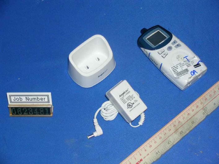
Click to zoom
Application Details
- Equipment Class
- CYY - Communications Receiver used w/Pt 15 Transmitter
- Date of Grant
- Mar 21, 2007
- Application Purpose
- Original Equipment
- Date of Application
- Mar 21, 2007
- Equipment Note
- Superheterodyne Receiver
- Frequency Range
- 926.00000000 - 927.60000000
- Company
- Angelcare Canada Inc.
- Country
- Canada
Documents & Files
Document Text
Text extracted from the exhibit documents filed with the FCC. Open a document above to read the original.
Users Manual
2 TABLE OF CONTENT Your Angelcare® Monitor’s components and special features . . . . . . . . . . . . . . . . . . . . . . . . . . . . . . . . .2 4 easy steps to operate your Angelcare ® Monitor . . . . . . . . . . . . . . . . . . . . . . . . . . . . . . . . . . . . . . . . . .3 Description of the icons . . . . . . . . . . . . . . . . . . . . . . . . . . . . . . . . . . . . . . . . . . . . . . . . . . . . . . . . . . . . .4 Testing your Angelcare ® Monitor . . . . . . . . . . . . . . . . . . . . . . . . . . . . . . . . . . . . . . . . . . . . . . . . . . . . . . .5 Warnings . . . . . . . . . . . . . . . . . . . . . . . . . . . . . . . . . . . . . . . . . . . . . . . . . . . . . . . . . . . . . . . . . . . . . . . .5 Care of your Angelcare ® Monitor . . . . . . . . . . . . . . . . . . . . . . . . . . . . . . . . . . . . . . . . . . . . . . . . . . . . . . .6 Troubleshooting . . . . . . . . . . . . . . . . . . . . . . . . . . . . . . . . . . . . . . . . . . . . . . . . . . . . . . . . . . . . . . . . . . .6 Warranty . . . . . . . . . . . . . . . . . . . . . . . . . . . . . . . . . . . . . . . . . . . . . . . . . . . . . . . . . . . . . . . . . . . . . . . . .7 Distributors . . . . . . . . . . . . . . . . . . . . . . . . . . . . . . . . . . . . . . . . . . . . . . . . . . . . . . . . . . . . . . . . . . . . . .14 2 (Two) 7.5 volt AC adapters RECHARGEABLE PARENTS UNIT (RECEIVER) & CHARGER NURSERY UNIT (TRANSMITTER) YOUR ANGELCARE ® MONITOR’S COMPONENTS SPECIAL FEATURES YOU WILL ALSO NEED : 4 AAA non-rechargeable batteries for the back-up power supply in the nursery unit (not included). Practical soothing night light. Nursery room temper atur e display on the par ents unit. Convenient belt clip. Choice of voice activ ated or continuous sound r eception modes. 4 AAA RECHARGEABLE BATTERIES FOR PARENTS UNIT 3 4 EASY STEPS TO OPERATE YOUR ANGELCARE ® MONITOR NURSERY UNIT (TRANSMITTER) • Insert 4 AAA regular batteries (not included) into nursery unit (for battery backup in case of power failure). • Connect AC adapter to nursery unit and plug adapter into an electrical outlet in the baby’s room. • After both units are properly installed (step1 and 2), turn them ON and then adjust microphone sensitivity level (if necessary). Adapter socket Microphone sensitivity dial Charger daptor socket Volume controls (up & down) USING THE BATTERY MODE • The monitor will revert to battery mode during a power failure only if batteries are inserted in both units. • Batteries in the nursery unit should be changed when the green light flashes. The battery icon and the nursery icon will also flash on the parents unit screen. • Parents unit should be recharged when icon blinks and a beep sound is heard. Note:Do not use Alkaline batteries in the parents unit. HOW TO USE YOUR MONITOR • To be warned if your units are “out of range”, switch the In Range Notification ON (optional). • If reception is not clear, switch to another channel. (see instructions for changing channel in the “ICON” section). • To avoid feedback (whistling sound),keep both units at least 3 meters apart (10 feet). STEP 1STEP 2 STEP 4 STEP 3 Power ON/OFF Channel selector Low battery indicator Channel selector ON/ OFF night light button Power ON/OFF In range ON/ OFF PARENTS UNIT (RECEIVER) • Insert 4 AAA NIMH rechargeable batteries (included) into parents unit. • Connect AC adapter to parents unit charger and plug adapter into an electrical outlet.Let charge for 15 continuous hours before using the monitor for the first time. • After both units are properly installed (step1 and 2),turn them ON and then adjust the volume control to the desired level. 4 ICONS ON YOUR ANGELCARE ® MONITOR ICON MEANING FUNCTION AND USE PARENTS UNIT Power Press and hold to turn ON or OFF. Channel key (8 channels) Press to enter or exit the Channel Selection Mode. Push the channel button on the parents unit. The “--” symbol will appear along with the In Range icon which will flash. Press the channel selector (top button) on the nursery unit until the night light halo fashes. Select the channel by gently pushing on the top button on the nursery unit (you will see the channel changing on the parents unit). Once the channel is selected, press and hold the nursery unit top button to confirm selection (halo will stop flashing). Both units are always on the same channel. If the interference persists, consult the Troubleshooting section. Temporary mute key Press to mute the speaker. parents unit will not receive sound for 2 minutes. Press again to reactivate the sound before the 2 minutes are up, if desired. Up and down sound volume Increases or decreases volume on the parents unit PARENTS UNIT’S SCREEN DISPLAY Nursery unit This icon will appear and the low battery icon will flash on the screen to inform you that the batteries are low in the nursery unit. Parents unit This icon will be ON only during Channel Selection Mode. Sound This icon indicates that the sound transmission is activated.It will flash when in Temporary Mute Mode. Battery level When the icon is completely dark,the batteries are fully charged.When it is clear, the batteries are low and the parents unit needs to be placed on the charger.When the batteries are TOO LOW, a “beep” will be heard every 15 seconds . The low battery icon will flash for 30 minutes before the unit shuts itself OFF. Sound level indicator Displays the sound level on the parents unit. There are 5 sound levels. Once you've chosen the desired level with the Up and Down keys, the bars will disap- pear and will start moving according to the sound transmitted by the nursery unit. The sound level indicator bars allow you to see the level of sound in your baby’s room. The louder the sounds from baby, the more bars appear. Channel and Baby’s room temperature display When turning ON the parents unit then the nursery unit, the channel number will be displayed on the parents unit screen for about one minute. It will then be replaced by the nursery room temperat…
Text truncated - open the document above for the full version.
Block Diagram
BD531`QBS`CML.2/tdi.2!.!Npo!Nbs!16!24;4:;34!3118 BD531.SGNPE.VT`QBS`CML.2/tdi.2!.!Npo!Nbs!16!22;26;68!3118
External Photos
INTERTEK TESTING SERVICES External Photos FCC ID: N7TAC420-R external photos - 1 of 1 External Photo - Front External Photo - Rear
ID Label/Location Info
AC420ParentRev.802/01/2007 AAA AAA AAA Model # AC420
Internal Photos
INTERTEK TESTING SERVICES Internal photos FCC ID: N7TAC420-R internal photos - 1 of 3 Internal Photo - 1 Internal Photo - 2 INTERTEK TESTING SERVICES Internal photos FCC ID: N7TAC420-R internal photos - 2 of 3 Internal Photo - 3 Internal Photo - 4 INTERTEK TESTING SERVICES Internal photos FCC ID: N7TAC420-R internal photos - 3 of 3 Internal Photo - 5
Operational Description
CIRCUIT DESCRIPTION OF AC420 B. PARENT UNIT 1. POWER SUPPLY DC 7.5V from Adapter or 4 X AAA size battery is input to U3 regulator. U3 outputs 3.8V DC which gives supply to other parts of circuit of the unit. 2. POWER SWITCH K5 is used as power on/off control of the unit. 3. DATA SHAPER Q7, Q8 form a data shaper which regulate the data transmitted from base, such as channel selection. 4. PILOT TONE DETECTOR Pilot tone received is filter at several stages of passive RC filters and amplified by Q16 and Q17. Then it is shaped at D7 and Q10 and fed into CPU U1 for recognition of audio from the base. Q5 and Q12 are then turned on for passing audio into speaker amplifier U2. 5. AUDIO OUTPUT AND LEVEL DETECTOR Demodulated signal is amplified by Q3 and Q15 and passes through audio switch Q5 once pilot tone is verified. After passing through the second switch Q12, the audio signal is amplified by the U2 and output as sound at speaker SPK1. Volume level output at speaker is controlled by K1 and K2 buttons which give CPU command to set terminals at R2, R3, R4 and R9 logic as varying the signal input to U2. Part of demodulated audio signal is amplified by Q1 and rectified by D1 and D5 to let CPU know the audio strength from the transmitter. The audio level is displayed by 10 levels bar of LCD display which is driven by CPU U1. 6. LCD display and Back light LCD display, LCD1 is driven by ports on CPU of LCD_C0 to LCD_C3 and LCD_S0 to LCD_S10. Back light of LCD is supported by LED1 which is driven by CPU U1. 7. RX RF MODULE OPERATION Radiated signal (926-927.6MHz) from nursery is collected by antenna HANT1 and passed through matching components HC48 and HL4 to dielectric filter HDF1 (927MHz). The received signal is amplified by HQ4 amplifier. Amplified received signal is mixed with VCO frequency (936.7- 938.3MHz) from HQ4 at HQ5 mixer. The output of HQ5 is of 10.7MHz and passes through first 10.7MHz filter HCF2 and amplified by HQ6 and then pass to 10.7MHz filter HCF1. Filtered 10.7MHz signal is fed into the input of IF IC HU1. Filtered 10.7MHz is mixed with 11.15MHz (HX1 oscillation) inside HU1 and a second IF 450kHz is generated. The 450kHz IF is output from pin 3 of HU1 and then filtered by components HL5,6 and HC69-71, 450kHz filter and then through HC67 back to HU1 pin 5 into internal demodulator. The audio is finally recovered from demodulator of HU1 which uses conventional quadrature detector contributed by HIFT1. The demodulated audio signal then passes into base band PCB at AF OUT pin (pin 1) of the module. AC420 FREQUENCY TABLE PARENT LCD DISPLAYCHANNELFREQUENCY TEST MODENORMALNUMBER(MHz) 00N.A.1926.0 01C12926.2 02C23926.4 03C34926.6 04C45926.8 05C56927.0 06C67927.2 07C78927.4 08C89927.6 REMARK: CHANNEL ONE ONLY DISPLAYED IN TEST MODE
Schematics
VTSGHI1:T`SFUFTU/tdi.2!.!Uvf!Opw!25!24;64;16!3117
Test Report
• The test results reported in this test report shall refer only to the sample actually tested and shall not refer or be deemed to refer to bulk from which such a sample may be said to have been obtained. • This report shall not be reproduced except in full without prior authorization from Intertek Testing Services Hong Kong Limited. • For Terms And Conditions of the services, it can be provided upon request. • The evaluation data of the report will be kept for 3 years from the date of issuance. Intertek Testing Services Hong Kong Ltd. 2/F., Garment Centre, 576 Castle Peak Road, Kowloon, Hong Kong. Tel: (852) 2173 8888 Fax: (852) 2785 5487 Website: www.hk.intertek-etlsemko.com Angelcare Monitors Inc. Application For Certification (FCC ID: N7TAC420-R) Superheterodyne Receiver 06234811 KL/ Ann Choy November 29, 2006 INTERTEK TESTING SERVICES FCC ID: N7TAC420-R i LIST OF EXHIBITS INTRODUCTION EXHIBIT 1: General Description EXHIBIT 2: System Test Configuration EXHIBIT 3: Emission Results EXHIBIT 4: Equipment Photographs EXHIBIT 5: Product Labelling EXHIBIT 6: Technical Specifications EXHIBIT 7: Instruction Manual EXHIBIT 8: Miscellaneous Information INTERTEK TESTING SERVICES FCC ID: N7TAC420-R ii MEASUREMENT/TECHNICAL REPORT Angelcare Monitors Inc. - MODEL: AC420 FCC ID: N7TAC420-R This report concerns (check one:) Original Grant X Class II Change _____ Equipment Type: Superheterodyne Receiver (example: computer, printer, modem, etc.) Deferred grant requested per 47 CFR 0.457(d)(1)(ii)? Yes No X If yes, defer until: date Company Name agrees to notify the Commission by: date of the intended date of announcement of the product so that the grant can be issued on that date. Transition Rules Request per 15.37? Yes No X If no, assumed Part 15, Subpart B for unintentional radiator - the new 47 CFR [04-05-05 Edition] provision. Report prepared by: Lam Chun Cheong, Kenneth Intertek Testing Services Hong Kong Ltd. 2/F., Garment Centre, 576, Castle Peak Road, Kowloon, Hong Kong. Phone: 852-2173-8474 Fax: 852-2741-1693 INTERTEK TESTING SERVICES FCC ID: N7TAC420-R iii Table of Contents 1.0 General Description ....................................................................................... 2 1.1 Product Description .......................................................................................... 2 1.2 Related Submittal(s) Grants.............................................................................. 2 1.3 Test Methodology............................................................................................. 3 1.4 Test Facility ...................................................................................................... 3 2.0 System Test Configuration ............................................................................ 5 2.1 Justification ...................................................................................................... 5 2.2 EUT Exercising Software.................................................................................. 5 2.3 Special Accessories ......................................................................................... 6 2.4 Equipment Modification .................................................................................... 7 2.5 Measurement Uncertainty................................................................................. 7 2.6 Support Equipment List and Description ........................................................... 7 3.0 Emission Results ........................................................................................... 9 3.1 Field Strength Calculation............................................................................... 10 3.2 Radiated Emission Configuration Photograph................................................. 11 3.3 Radiated Emission Data ................................................................................. 12 3.4 Conducted Emission Configuration Photograph................................................ 15 3.5 Conducted Emission Data ................................................................................ 16 4.0 Equipment Photographs .............................................................................. 18 5.0 Product Labelling ......................................................................................... 20 6.0 Technical Specifications.............................................................................. 22 7.0 Instruction Manual....................................................................................... 24 8.0 Miscellaneous Information .......................................................................... 26 8.1 Discussion of Pulse Desensitization................................................................ 27 8.2 Calculation of Average Factor......................................................................... 28 8.3 Emissions Test Procedures ............................................................................ 29 INTERTEK TESTING SERVICES FCC ID: N7TAC420-R iv List of attached file Exhibit type File Description filename Test Report Test Report report.pdf Operation Description Technical Description descri.pdf Test Setup Photo Radiated & Conducted Emission config photos.doc Test Report Conducted Emission Test Result conducted.pdf External Photo External Photo external photos.doc Internal Photo Internal Photo internal photos.doc Block Diagram Block Diagram block.pdf Schematics Circuit Diagram circuit.pdf ID Label/Location Label Artwork and Location label.pdf User Manual User Manual manual.pdf INTERTEK TESTING SERVICES FCC ID: N7TAC420-R 1 EXHIBIT 1 GENERAL DESCRIPTION INTERTEK TESTING SERVICES FCC ID: N7TAC420-R 2 1.0 General Description 1.1 Product Description The Equipment Under Test (EUT) is a superheterodyne receiver (Parent Unit of Sound Baby Monitor) operating at 926.000MHz-927.600MHz with 9 channels. The EUT is powered by 4 x “AAA” size 1.5Vdc alkaline battery, 4 x “AAA” Ni-MH type…
Text truncated - open the document above for the full version.
Test Report
Report No.: 06234811 RX Mode Ctrl No.: N/A PAGE 1 Tested By:Hong, Report No.:06234811 Scan Settings (1 Range) |--------- Frequencies -----------||----------- Receiver Settings ------------| Start Stop Step IF BW Detector M-Time Atten Preamp OpRge 150k 30M 5k 10k PK+AV 10ms AUTO LN OFF 60dB Final Measurement: x QP / + AV Meas Time: 1 s Subranges: 16 Acc Margin: 20dB Transducer No. Start Stop Name 2 1 9k 30M EW0700 12 9k 30M EW1449 0 10 20 30 40 50 60 70 80 90 dBuV 100 0.15 MHz 30 110 F15Q F15A Report No.: 06234811 RX Mode Ctrl No.: N/A Tested By:Hong, Report No.:06234811 Scan Settings (1 Range) |--------- Frequencies -----------||----------- Receiver Settings ------------| Start Stop Step IF BW Detector M-Time Atten Preamp OpRge 150k 30M 5k 10k PK+AV 10ms AUTO LN OFF 60dB Final Measurement Results: no Results
Test Setup Photos
INTERTEK TESTING SERVICES The Worst Case Configuration Photographs FCC ID: N7TAC420-R config photos (radiated emission) - 1 of 1 Radiated Emission Front View Rear View INTERTEK TESTING SERVICES The Worst Case Configuration Photographs FCC ID: N7TAC420-R config photos (conducted emission) - 1 of 2 Conducted Emission Front View Right Side View INTERTEK TESTING SERVICES The Worst Case Configuration Photographs FCC ID: N7TAC420-R config photos (conducted emission) - 2 of 2 Conducted Emission Left Side View
Contact Information
Applicant
Mark Buckle(Technical Manager)
Technical Contact
Intertek Testing Services Hong Kong Ltd.Kenneth Lam
[email protected](852) 2173 8474
Flat D, 5/F., Garment Centre, · Kowloon · Hong Kong
Non-Technical Contact
Intertek Testing Services Hong Kong Ltd.Kenneth Lam
[email protected](852) 2173 8474
Test Firm
Intertek Testing Services Hong KongBilly Chow
Technical Specifications
| # | Rule Parts | Frequency Range | Power Output |
|---|---|---|---|
| 1 | 15B | 926 MHz - 927.6 MHz | - |
Other Applications from Angelcare Canada Inc.
N7TAC1300T
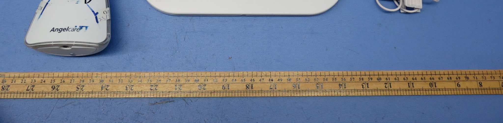
Dec 02, 2015Video Baby Monitor - Baby Unit
Equipment Class
DSS - Part 15 Spread Spectrum Transmitter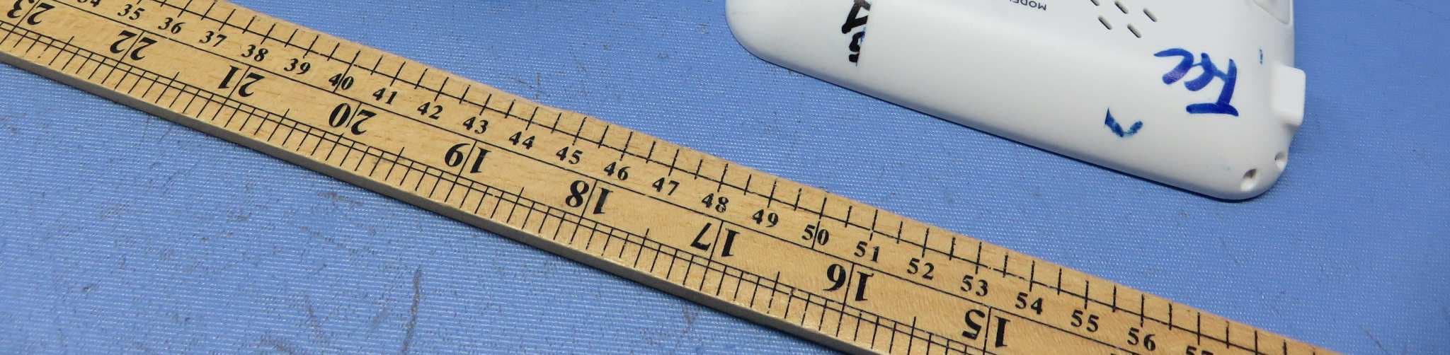
N7TAC1300R
Dec 02, 2015Video Baby Monitor - Parent Unit
Equipment Class
DSS - Part 15 Spread Spectrum Transmitter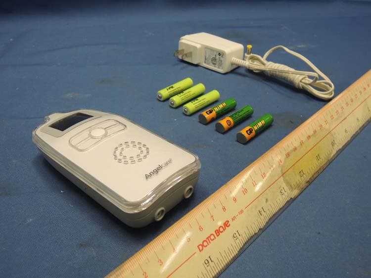
N7TAC423R
Jan 09, 2014900MHz Superheterodyne Receiver (Parent Unit)
Equipment Class
CYY - Communications Receiver used w/Pt 15 Transmitter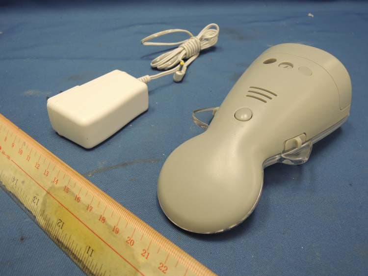
N7TAC423T
Jan 09, 2014900MHz Analog Modulation Baby Monitor (Baby Unit)
Equipment Class
DXX - Part 15 Low Power Communication Device Transmitter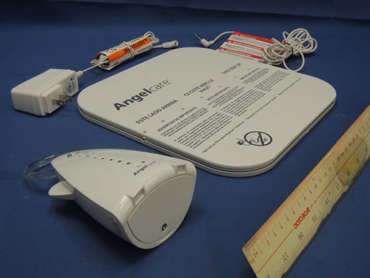
N7TAC701T
Jan 01, 20141.9GHz DECT Baby Monitor - Baby Unit
Equipment Class
PUB - Part 15 Unlicensed PCS Base Station