N7ZEA100ADSL Modem With USB Interface
Turbocomm Tech Inc.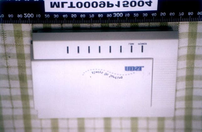
Click to zoom
Application Details
- Equipment Class
- JBP - Part 15 Class B Computing Device Peripheral
- Date of Grant
- Apr 29, 2001
- Application Purpose
- Original Equipment
- Date of Application
- Apr 29, 2001
- Equipment Note
- ADSL Modem With USB Interface
- Company
- Turbocomm Tech Inc.
- Country
- Taiwan
Documents & Files
Document Text
Text extracted from the exhibit documents filed with the FCC. Open a document above to read the original.
Users Manual
EA100 ADSL USB Modem Installation Guide Microsoft® Windows 98, 2000 Driver Version v1.05.0004q / Re.001 EA100 USB DSL Modem The GlobeSpan USB DSL Modem Reference Design - Installation Guide and User’s Manual September 22, 2000 GAUM-0003 Rev. 0.9 Table of Contents ABOUT THIS MANUAL.....................................................................................................................1 PREFACE..........................................................................................................................................2 T HE GLOBESPAN USB ADSL MODEM MANUAL...................................................................................2 CHAPTER 1: OVERVIEW.................................................................................................................3 A BOUT ADSL...................................................................................................................................3 P ROTOCOL AND DEVICE DRIVER SELECTION........................................................................................3 F EATURES.......................................................................................................................................5 CHAPTER 2: GLOBESPAN USB ADSL MODEM INSTALLATION AND SOFTWARE SETUP........6 S OFTWARE SETUP............................................................................................................................7 M ODEM INSTALLATION.......................................................................................................................9 CHAPTER 3: CUSTOMIZING COMMUNICATION SETTINGS.......................................................11 CHAPTER 4: UPDATING THE GLOBESPAN USB ADSL MODEM SOFTWARE...........................12 CHAPTER 5: GLOBESPAN CONTROL PANEL APPLICATION....................................................13 D EVELOPMENT MODE.....................................................................................................................17 CHAPTER 6: SOFTWARE UNINSTALL.........................................................................................24 APPENDIX A: MODIFYING TCP/IP NETWORKING OPTIONS......................................................26 WAN USB D RIVER........................................................................................................................26 Microsoft Windows 98, First and Second Editions................................................................26 Microsoft Windows 2000......................................................................................................29 LAN USB D RIVER..........................................................................................................................31 Microsoft Windows 98, First and Second Editions................................................................31 Microsoft Windows 2000......................................................................................................34 ATM USB D RIVER.........................................................................................................................36 Microsoft Windows 98, Second Edition................................................................................36 Microsoft Windows 2000......................................................................................................40 APPENDIX B: FCC/INDUSTRY CANADA REQUIRED INFORMATION.........................................42 FCC R EQUIRED INFORMATION:........................................................................................................42 I NDUSTRY CANADA REQUIRED INFORMATION.....................................................................................44 GlobeSpan, Inc. Proprietary – Use Pursuant to NDA 1 About This Manual This manual provides a comprehensive user’s guide and installation manual for GlobeSpan USB modems. It has been organized in such a way to make it easy to follow by users worldwide. In order to ensure optimal comprehension, the following list provides brief descriptions of the formatting styles used throughout this manual. q Commands: Commands are always referred to by using the word “click” before them. These commands are always shown as bold-faced words. For example, click Next, click OK, or click Cancel. q Names of Windows (Dialog Boxes): The names of the windows (also referred to as dialog boxes) that appear on the PC screen are always referred to in quotes. For example, the “Setup Complete” window. q Names of Options in Windows: The names of options to choose from inside the windows that appear on the PC screen are always referred to in italics. For example, choose the Yes, I want to restart my computer now option from the window. q Notes: In some cases, preparatory or cautionary information is needed before proceeding onto the next step in an installation process. This kind of information is provided in the form of notes, which are always referred to in bold-faced and italicized letters. For example, Note: To access the GlobeSpan Control Panel, the driver must be running. Also, make sure the USB cable is plugged into the modem. 2GlobeSpan, Inc. Proprietary – Use Pursuant to NDA Preface The GlobeSpan USB ADSL Modem Manual This manual contains information regarding the installation, operation, and configuration of the GlobeSpan USB ADSL Modem. Additionally, it outlines the use of the Control Panel Application. The following chapters are included in this manual: • Chapter 1: “Overview” offers a brief description of ADSL, protocol and device driver selection, and the features of the GlobeSpan USB ADSL Modem. • Chapter 2: “GlobeSpan USB ADSL Modem Installation and Software Setup” describes the steps for installing the GlobeSpan USB ADSL Modem. The software installation procedure is detailed. • Chapter 3: “Customizing Communication Settings” provides detailed steps for altering the ATM Virtual Path ID (VPI), ATM Virtual Circuit ID (VCI), Encapsulation…
Text truncated - open the document above for the full version.
Block Diagram
5 5 4 4 3 3 2 2 1 1 DD CC BB AA BLOCK DIAGRAM GLOBESPAN DSP GS7070-174-002D ANCHOR CHIP EZ-USB AN2131QC LED INDICATOR CRYSTAL 27.280MHz NVRAMCRYSTAL 12MHz USB JACK RAM 32K X 8 ANALOG FRANT E GT3180-01-AND LINE DRIVER RECEIVER FILTER DAA LINE FILTER POWER SUPPLY LINE EA-100(DMT only) 3.0 MULTI-MODE DMT USB-ADSL MODEM TURBOCOMM TECH. INC. B 25Thursday, October 19, 2000 Title SizeDocument NumberRev Date:Sheet of +12V +3.3V +5V
Cover Letter(s)
From: certadm [[email protected]] To: [email protected] Cc: [email protected] Subject: TURBOCOMM TECH. INC., FCC ID:N7ZEA100, AN01T1245 Notice_content ------------- Question #1: User manual does not contian information required in 15.21, 15.27 and 15.105(b). Please provide revised user manual. Best Regards Mike Kuo / TCB Certifier The items indicated above must be submitted be fore processing can continue on the above referenced application. Failu re to provide the requested information within 60 days of the original e-mail date may result in application dismissal and forfeiture of the f iling fee. Also, please note that partial responses increase processing time and should not be submitted. Any questions about the content of t his correspondence should be directed to the e-mail address listed belo w the name of the sender.
External Photos
MAX LIGHT Report Number: MLT0009P15004 FCC ID: N7ZEA100 Technology Lab MAX LIGHT Report Number: MLT0009P15004 FCC ID: N7ZEA100 Technology Lab
ID Label/Location Info
MAX LIGHT Report Number: MLT0009P15004 FCC ID: N7ZEA100 Technology Lab Label Format: Label Position: This device complies with Part15 of the FCC Rules. Operation is subject to the following two conditions: (1) This device may not cause harmful interference,and (2) This device must accept any interference received ,including. Interference that may cause undesired operation. Model: EA100 FCC ID: N7ZEA100 MADE IN TAIWAN Equipment Lable 3.0 cmX2.0 cm Rear View
Internal Photos
MAX LIGHT Report Number: MLT0009P15004 FCC ID: N7ZEA100 Technology Lab MAX LIGHT Report Number: MLT0009P15004 FCC ID: N7ZEA100 Technology Lab
Test Report
Product : USB ADSL Modem Applicant : TURBOCOMM TECH. INC. FCC ID : N7ZEA100 Model : See Appendix II Report No. : MLT0009P15004 Test Date : October 27.2000 Test By Max Light Technology Co.,Ltd. Room 5, 8F, No.125, Section 3 Roosevelt Road, Taipei, Taiwan., R.O.C. Tel: 886-2-2363-2447 Fax: 886-2-2363-2597 T T h h e e t t e e s s t t r r e e p p o o r r t t c c o o n n s s i i s s t t s s o o f f 2 2 2 2 p p a a g g e e s s i i n n t t o o t t a a l l . . I I t t m m a a y y b b e e d d u u p p l l i i c c a a t t e e d d c c o o m m p p l l e e t t e e l l y y f f o o r r l l e e g g a a l l u u s s e e w w i i t t h h t t h h e e a a l l l l o o w w a a n n c c e e o o f f t t h h e e a a p p p p l l i i c c a a n n t t . . I I t t s s h h a a l l l l n n o o t t b b e e r r e e p p r r o o d d u u c c e e d d e e x x c c e e p p t t i i n n f f u u l l l l , , w w i i t t h h o o u u t t t t h h e e w w r r i i t t t t e e n n a a p p p p r r o o v v a a l l o o f f o o u u r r l l a a b b o o r r a a t t o o r r y y . . MAX LIGHT MEASUREMENT REPORT Page: 2/22 Report Number: MLT0009P15004 FCC ID: N7ZEA100 Technology Lab Table of Contents : I. General 4. II. Conducted Emissions Requirements 9. III. Radiated Emissions Requirements 14. Appendix I (EUT Test Setup) 20. Appendix II (Model List) 23. MAX LIGHT MEASUREMENT REPORT Page: 3/22 Report Number: MLT0009P15004 FCC ID: N7ZEA100 Technology Lab CERTIFICATION We here by verify that : The test data, data evaluation, test procedures and equipment configurations shown in this report were made in accordance with the procedures given in ANSI C63.4-1992. All test were conducted by MLT(Max Light Technology Co.,Ltd) Room 5, 8F, No.125, Section 3 Roosevelt Road, Taipei, Taiwan, R.O.C Also, we attest to the accuracy of each. We further submit that the energy emitted by the sample EUT tested as described in the report is in compliance with Class B radiated and conducted emission limit of FCC Rules Part 15 Subpart B. EUT: USB ADSL Modem Applicant: TURBOCOMM TECH. INC. 4F-2, No.171, Sung-Tech Road, Taipei ,Taiwan Manufacturer: TURBOCOMM TECH. INC. No.369,Sec.3 Chun Cheng East Road, Wu Chuan Tsun,Ta Yuan Hsiang,Tao Yaun Hsien,Taiwan,R.O.C. Model No: See Appendix II FCC ID: N7ZEA100 Prepared by :Approved by : Country Huang Roger Chen MAX LIGHT MEASUREMENT REPORT Page: 4/22 Report Number: MLT0009P15004 FCC ID: N7ZEA100 Technology Lab I. GENERAL 1.1 Introduction The following measurement report is submitted on behalf of TURBOCOMM TECH. INC. In support of a Class B Digital Device certification in accordance with Part2 Subpart J and Part 15 Subpart A And B of the Commission’s and Regulations. 1.2 Description of EUT EUT: USB ADSL Modem Applicant: TURBOCOMM TECH. INC. 4F-2, No.171, Sung-Tech Road, Taipei ,Taiwan Manufacturer: TURBOCOMM TECH. INC. No.369,Sec.3 Chun Cheng East Road, Wu Chuan Tsun,Ta Yuan Hsiang,Tao Yaun Hsien,Taiwan,R.O.C. Model No: See Appendix II FCC ID : N7ZEA100 Power Type: Powered by PC Phone Cable: RJ-11Cx2(Nonshielded, 7’ long ,Plastic hoods) During testing the EUT was operated at Tx or Rx mode for each emission measured(P.S Run “Ping (IP Address) –T –L 1000” comment in Dos Mode). This was done in order to ensure that maximum emission levels were attained. MAX LIGHT MEASUREMENT REPORT Page: 5/22 Report Number: MLT0009P15004 FCC ID: N7ZEA100 Technology Lab 1.3 Description of Support Equipment In order to construct the minimum system which required by the ANSI C63.4-1991, following equipments were used as the support units. Computer: IBM Model No.: 16W Serial No.: BNC345M FCC ID: FCC DOC Keyboard: IBM Model No.: KB-9930 Serial No.: 09N5395 FCC ID: FCC DOC Monitor: IBM Model No.: 10L6145 030 Serial No.: 23-092079 FCC ID: FCC DOC Mouse: IBM Model No.: 0180-05N Serial No.: 23-96142 FCC ID: EMJMUSJJ Printer: PANASONIC Model No.: KX-P1080I Serial No.: 7CKAKE98933 FCC ID: ACJ5Z6KX-P10801 ADSL Simulator: Gold Span Model No.: GS-0192 Serial No.: N/A MAX LIGHT MEASUREMENT REPORT Page: 6/22 Report Number: MLT0009P15004 FCC ID: N7ZEA100 Technology Lab Modem: Askey (External Fax / Data Modem) Model No.: WS1414VE Serial No.: IAH-10811 FCC ID: H8N1414VE MAX LIGHT MEASUREMENT REPORT Page: 7/22 Report Number: MLT0009P15004 FCC ID: N7ZEA100 Technology Lab 1.4 Configuration of System Under Test During testing the EUT(USB ADSL Modem ) was connected to the USB port of IBM ’PC. So there is no need for additional I/O card. A mouse was connected to the mouse port and a printer was connected to the parallel port. A external modem connected the serial port and the external modem connected with two unterminated telephone cables on the line and phone jack. The Phone jack of EUT was connected to a telephone. The line jack of EUT was connected to a simulator of ADSL. 1.5 Test Procedure All measurements contained in this report were performed according to the techniques described in Measurement procedure ANSI C63.4-1992 "Measurement of unIntentional Radiators." Power Supply PCMonitor Printer To ADSL Simulator Keyboard Mouse EUT RS-232 RS-232 Modem TEL RJ-11C Cable USB Cable MAX LIGHT MEASUREMENT REPORT Page: 8/22 Report Number: MLT0009P15004 FCC ID: N7ZEA100 Technology Lab 1.6 General Test Condition The conditions under which the EUT operates were varied to determine their effect on the equipment's emission characteristics. The final configuration of the test system and the mode of operation used during these tests was chosen as that which produced the highest emission levels. However, only those conditions which the EUT was considered likely to encounter in normal use were investigated. The system's radiated and conducted emissions were investigated while the computer alternately transferred data to the EUT (1000 bytes). Run “Ping (IP Address -T –L 1000)” comment which sent a continuous stream of 1000 Bytes data to EUT and transferred data to and from the EUT was proven to worst case emissions. The system's physical layout and cabling was randomly arranged to ensure that…
Text truncated - open the document above for the full version.
Test Setup Photos
MAX LIGHT MEASUREMENT REPORT Page: 15/22 Report Number: MLT0009P15004 FCC ID: N7ZEA100 Technology Lab 3.3 Test Configuration: Front View of The Test Configuration MAX LIGHT MEASUREMENT REPORT Page: 16/22 Report Number: MLT0009P15004 FCC ID: N7ZEA100 Technology Lab Rear View of The Test Configuration
Test Setup Photos
MAX LIGHT MEASUREMENT REPORT Page: 11/22 Report Number: MLT0009P15004 FCC ID: N7ZEA100 Technology Lab Rear View of The Test Configuration
Contact Information
Applicant
Ken Hsu(Senior Engineer)
Test Firm
Max Light Technology Co., Ltd.Jesse Tien
Technical Specifications
| # | Rule Parts | Frequency Range | Power Output |
|---|---|---|---|
| 1 | 15B | - | - |
Other Applications from Turbocomm Tech Inc.

N7ZRT-900W
Jun 07, 2006Wireless AP
Equipment Class
DTS - Digital Transmission System
N7ZWVM-1101
May 11, 2006Wireless Video Module
Equipment Class
NII - Unlicensed National Information Infrastructure TX
N7ZWLI303
Dec 01, 2005WIRELESS LAN 802.11/b,g
Equipment Class
DTS - Digital Transmission System
N7ZEC420
Oct 23, 2005CABLE MODEM
Equipment Class
JBP - Part 15 Class B Computing Device Peripheral
N7ZRT-710S
Jan 01, 2002Broadband Sharing Router
Equipment Class
JBP - Part 15 Class B Computing Device Peripheral