N7ZECM100
Turbocomm Tech Inc.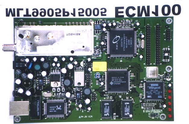
Click to zoom
Application Details
- Equipment Class
- JBP - Part 15 Class B Computing Device Peripheral
- Date of Grant
- Jul 25, 1999
- Application Purpose
- Original Equipment
- Date of Application
- May 27, 1999
- Company
- Turbocomm Tech Inc.
- Country
- Taiwan
Documents & Files
Document Text
Text extracted from the exhibit documents filed with the FCC. Open a document above to read the original.
Users Manual
TurboComm DAZ8801F / ECM100 User’s Manual Page 1 D D A A Z Z 8 8 8 8 0 0 1 1 F F / / E E C C M M 1 1 0 0 0 0 U U s s e e r r ’ ’ s s M M a a n n u u a a l l TurboComm DAZ8801F / ECM100 User’s Manual Page 2 Introduction Congratulations on Your Purchase! Your new DAZ8801F / ECM100 DOCSIS Cable Modem will provide you with high-speed access to the Internet through your cable TV (CATV) network - access at a fraction of the time it takes traditional telephone modems. In addition, your service will be always connected. Those two features give you the information you want, when you want it ... and your telephone line is kept free. Important Rules for Safe Operation In addition to the careful attention devoted to quality standards in the manufacture of your TurboComm DOCSIS Cable Modem, safety is a major factor in the design of every product. However, safety is your responsibility, too. This section lists important information that will help assure your enjoyment and proper use of the TurboComm Cable Modem and accessory equipment. Please read them carefully before operating and using your modem. TurboComm DAZ8801F / ECM100 User’s Manual Page 3 Installation Read and Follow Instructions - You should read all the safety and operating instructions before operating the modem. Follow all operating instructions. Retain Instructions - You should save all the safety and operating instructions, for your future reference. Heed Warnings - Comply with all warnings on the products and in the operating instructions. Check Power Sources - Operate this product only from the type of power source indicated on the product's marking label. If you are not sure of the type of power supplied to your home, consult your dealer or local power company. Be Careful of Overloading - Do not overload wall outlets or extension cords, as this can result in a risk of fire or electric shock. Overloaded AC outlets, extension cords, frayed power cords, damaged or cracked wire insulation, and broken plugs are dangerous. They may result in a shock or fire hazard. Periodically examine the cord, and, if its appearance indicates damage or deteriorated insulation, have it replaced by your service technician. Protect Power Cords - Route power supply cords so that they are not likely to be walked on or pinched by items placed upon or against them. Pay particular attention to cords where they are attached to plugs and convenience receptacles, and examine the point where they exit from the product. Check Ventilation - Slots and openings in the enclosure are provided for ventilation to ensure reliable operation of the product and to protect it from overheating. Do not block or cover these openings. Never block these openings by placing the product on a bed, sofa, rug, or other similar surface. Never place this product near or over a radiator or heat register, or any other heat source (including amplifiers). Do not place this product in a built-in installation, such as a bookcase or equipment rack, unless you provide proper ventilation. Do Not Use Accessories - Do not use attachments, unless they are recommended by TurboComm, as they may cause electrical or fire hazards. Use the Recommended AC Adaptor - You must use the Adaptor that comes with your TurboComm Cable Modem. Do Not Use Near Water - Do not use this product near water - for example, near a bath tub, wash bowl, kitchen sink or laundry tub, in a wet basement or near a swimming pool, and the like. Do Not Place Near High Temperature Source -for example near a steamer, Kitchen range fire, and the like. Use Caution in Mounting This Product - Do not place this product on an unstable surface or support. The product may fall, causing serious injury to a child or adult, as well as serious damage to the product. Use Care in Moving Product-and-Cart Combinations - Quick stops, excessive, force and uneven surfaces may cause the product-and-cart combination to overturn. TurboComm DAZ8801F / ECM100 User’s Manual Page 4 Ground the Cable System - Be sure that the outside cable system is grounded, so as to provide some protection against voltage surges and built-up static charges. Section 810 of the National Electric Code, ANSI/NFPA No. 70-1984 (Section 54 of the Canadian Electrical Code, Part 1) provides information with respect to proper grounding of the cable system. Do not disconnect RF cable from your TurboComm Cable Modem while the power to your modem is on. Use Unplug Power Before Cleaning - Do not use liquid cleaner or aerosol cleaner. Use a damp cloth for cleaning. Keep Objects Out of Openings - Never push objects of any kind into this product through openings, as they may touch dangerous voltage or "short-out" parts, which could result in a fire or electric shock. Never spill liquid on the product. Protect From Lightning - For added protection for this product during a lightning storm, or when it is left unattended and unused for long periods of time, unplug it from the wall outlet, and disconnect the cable system. This will prevent damage to the product due to lightning and power line surges. Take at least 10 seconds between DC plug off and on. Service Do Not Remove Covers - Do not attempt to service this product yourself, as opening or removing covers may expose you to dangerous voltage or other hazards. Refer all servicing to qualified service personnel. Unplug this product from the wall outlet carefully, as the AC adaptor may be hot. Refer Servicing to Qualified Service Personnel Under the Conditions Listed Below When the power supply cord or plug is damaged. If liquid has been spilled or objects have fallen into the product. If the product has been exposed to rain or water. If the product does not operate normally by following the operating instructions. Adjust only those controls that are covered by the operating instructions. If the product has been dropped or the cabinet has been damaged. When the product exhibits a distinct change in performance, such as the inability to perform basic …
Text truncated - open the document above for the full version.
External Photos
MAX LIGHT Report Number: MLT9905P15005 FCC ID: N7ZECM100 Technology Lab MAX LIGHT Report Number: MLT9905P15005 FCC ID: N7ZECM100 Technology Lab MAX LIGHT Report Number: MLT9905P15005 FCC ID: N7ZECM100 Technology Lab MAX LIGHT Report Number: MLT9905P15005 FCC ID: N7ZECM100 Technology Lab MAX LIGHT Report Number: MLT9905P15005 FCC ID: N7ZECM100 Technology Lab MAX LIGHT Report Number: MLT9905P15005 FCC ID: N7ZECM100 Technology Lab MAX LIGHT Report Number: MLT9905P15005 FCC ID: N7ZECM100 Technology Lab MAX LIGHT Report Number: MLT9905P15005 FCC ID: N7ZECM100 Technology Lab
ID Label/Location Info
MAX LIGHT Report Number: MLT9905P15005 FCC ID: N7ZECM100 Technology Lab Label Format: Label Position(DAZ8801F Series): This device complies with Part15 of the FCC Rules. Operation is subject to the following two conditions: (1) This device may not cause harmful interference,and (2) This device must accept any interference received ,including. Interference that may cause undesired operation. Model: DAZ8801F Series / ECM100 Series FCC ID: N7ZECM100 MADE IN TAIWAN Equipment Lable 3.2CMX1.5CM Reverse View MAX LIGHT Report Number: MLT9905P15005 FCC ID: N7ZECM100 Technology Lab Label Position(ECM100 Series): Equipment Lable 5CMX1.5CM Reverse View
Schematics
8 8 7 7 6 6 5 5 4 4 3 3 2 2 1 1 DD CC BB AA FOR LBT4030 (U4) ONLY Vout=1.25(1+R130/R126) AIC-1563 LM3578A Vout=(R53/R54)+1 Route +2V away from analog section PCX2-3.SCHX1 POWER VER5.21 TURBO COMMUNICATION INC C 212Wednesday, May 12, 1999 Title SizeDocument NumberRev Date:Sheet of +12V+12V +12V +12V +12V +12V +5D +5D +3.3V +5VA +VCC +5V +3.3VDC +3.3VLB +32V +2V +9VA +5D D4 1N4148 S R72 1K S2 1% R87 390K S2 D7 1N4148 S R118 220 S2 R129 390K S2 R126 2K S2 1% R82 220 S2 R130 3K3 S2 1% + C50 470U/16V+ C54 100U/16V + C70 470U/16V + C47 10U/25V R61 3K9 S2 5% R100 100 S3 R60 270K S2 R138 270K S2 U17 LM3578A SOP8 1 2 3 45 6 7 8 IN- IN+ OSC GNDEMIT COLL CURR/L VIN U14 AIC 1563 DIP 1 2 3 45 6 7 8 SC SE TC GNDFB VCC IS BST U10 AIC 1563 DIP 1 2 3 45 6 7 8 SC SE TC GNDFB VCC IS BST JP6 HEADER 2*4 2.54mm 1 3 5 7 2 4 6 8 + + + + + + + + + C61 470U/16V R54 10K S2 U20 LM3578A SOP8 1 2 3 45 6 7 8 IN- IN+ OSC GNDEMIT COLL CURR/L VIN MOV1 ZNR 68V/7mm L30 BEAD/600 S3 L13 TFU0940V NC L11 BEAD RADIAL L14 BEAD RADIAL JP9 POWER JACK L7 BEAD/600 S3 R53 10K S2 + C73 10U/100V + C78 10U/100V R86 124K S2 1% L9 330uH DR0912 L10 470uH DR0912 L8 330uH DR0912 L5 330uH DR0912 C84 .1u/50V X7R S2 C98 .1u/50V X7R S2 C102 .1u/50V X7R S2 C131 .1u/50V X7R S2 C135 .1u/50V X7R S2 C136 .1u/50V X7R S2 + C57 470U/16V C139 .1u/50V X7R S2 C151 .1u/50V X7R S2 C69 1000P/50V X7R S2 C143 1000P/50V X7R S2 C87 .01u/50V X7R S2 C110 470P/50V X7R S2 C140 470P/50V X7R S2 C114 .033u/50V X7R S2 C142 .033u/50V X7R S2 C62 22P/50V NPO S2 C74 22P/50V NPO S2 C63 820P/50V NPO S2 C75 820P/50V NPO S2 C109 100P/50V NPO S2 R62 0.15 S5025 D2 1N5819 RADIAL R45 0.15 S5025 D1 1N5819 RADIAL D3 1N5819 RADIAL D8 1N5819 RADIAL U7 LM78L09 TO-92 13 2 VIVO GND + C81 1000U/25V C99 .1u/50V X7R S2 C133 .1u/50V X7R S2 L23 68uH DR0912 + C225 10OU/25V + C226 100U/25V R217 0.15 S5025 R216 0.15 S5025 R215 BEAD/600 S3 R59 3K S2 1% L27 68uH DR0912 L25 BEAD/600 S3 GND +9VA +2V VCC +3.3VDC +5VA +32V +3.3VLB 8 8 7 7 6 6 5 5 4 4 3 3 2 2 1 1 DD CC BB AA -15 TO +15dBm 88 to 860MHz TUNER RF In 5mA 12131415 PCX3-2.SCHX1 DOWNSTREAM RF VER5.21 TURBO COMMUNICATION INC C 312Wednesday, May 12, 1999 Title SizeDocument NumberRev Date:Sheet of TUNER_UPST_IF TUNER_RF_AGC TUNER_5VA TUNER_5VB TUNER_32V TUNER_IF_AGC TUNER_SCLTUNER_SCL_LP TUNER_SDATUNER_SDA_LP +5VA +5VA +32V +5VA +5VA +5VA C100 .01u S1 C96 .1u S1 R136 NC S1 C145 NC S1 U11 CVA8XMA 1234567891011 TXRF/AGC+5V+32V+5VSCKSDAIF/AGCADC/BIASIF/OUT+IF/OUT- R116 100 S1 R123 100 S1 C134 1000P S1 C137 1000P S1 L18 BEAD/600 S3 L22 BEAD/600 S3 L24 BEAD/600 S3 + C56 100U/16V + C60 100U/16V C92 1000P S1 R135 NC S1 R134 NC S1 C55 1000P S1 + C67 10U/100V JP11 HEADER 1*2 2.54mm 12 12 L35 COMMON CHOKE 23294977A C127 .01u/50V X7R S3 C124 .1u/50V X7R S3 L26 BEAD/600 S3 R125 13K S1 C141 .1uS1 R132 1K S1 R78 13K S1 R69 1K S1 R76 56K S1 C88 100P S1 R79 15K1 S1 R75 6K8 S1 C154 .1u S1 R124 43K S1 C218 100 S1 C125 .1u S1 R128 4K71 S1 R127 15K1 S1 + - U30A MC33202 SOP8 3 2 1 8 4 + - U30B MC33202 SOP8 5 6 7 TUNER_UPST_IF RF_AGC TUNER_SCL TUNER_SDA IF_OUT- IF_OUT+ IF_AGC 8 8 7 7 6 6 5 5 4 4 3 3 2 2 1 1 DD CC BB AA AS103-59 PACKAGE IS MSOP Note : L31,L32,L1001 no parallel Note : L20,L1002 no parallel PCX4-2.SCHX1 PCX CABLE MODEM VER5.21 TURBO COMMUNICATION INC C 412Monday, May 03, 1999 Title SizeDocument NumberRev Date:Sheet of UPST IF OUT- UPST IF OUT+ PGA_DATA PGA_CLK /PGA_DATAEN +5VA +5VA +5VA +9VA C150 NC S1 C90 .1u S1 C85 .1u S1 C83 .1u S1 C82 .01u S1 R140 200 S1 R139 NC S1 R141 NC S1 R133 150 S1 R137 39 S1 R131 150 S1 U15 AD8321 SOP20 1 2 3 4 5 6 7 8 9 1011 12 13 14 15 16 17 18 19 20 SDATA CLK DATAEN GND VOCM /PD VCC VCC VCC VOUTGND GND GND BYP GND GND VCC VREF VIN VCC L15 BEAD/600 S3 T1 WB3040SM(4:1) 1 2 34 6 5 R209 1K S1 C223 NC C224 NC C221 .1u S1 C116 .01u S1 C91 .01u S1 C89 220P S1 R211 75 S1 R214 0 S1 R213 0 S1 R212 0 S1 NC L36 390nH S3225 K C1005 .01u S1 C146 S1 NC C155 100P S1 L32 180nH S3225 K C153 180P S1 L31 150nH S3225 K C148 27P S1 C147 100P S1 C1010 NC S1 C1009 NC S1 L1001 0 S3 C144 150P S1 R85 100 S1 R65 30 S1 R63 390 S1 R66 390 S1 R210 0 S1 NC U27 AS103-59 MSOP8 8 7 6 54 3 2 1 J3 V2 V1 J2GND J1 VS GND U28 74HC04 SOP14 1 2 3 4 5 6 78 9 10 11 12 13 14 A1 Y1 A2 Y2 A3 Y3 GNDY4 A4 Y5 A5 Y6 A6 VCC C152 10P S1 L1002 270nH S3225 K C220 .01u S1 C1004 10P S1 L1000 0 S3 C1001 10P S1 R64 1K S1 C222 .1u S1 C101 NC S1 C122 .01u S1 C1103 NC S1 C1002 56P S1 C1003 56P S1 C129 NC S1 C1101 0 S1 L20 S3225 NC C1108 100P S1 C1106 100P S1 R10001K S1 R10011K S1 R10021K S1 C86 .1u S1 C1107 100P S1 C93 .1u S1 C120 .1u S1 C1100 .01u S1 TUNER_UPST_IF PGA_DATA PGA_CLK /PGA_DATAEN UPST_IF_OUT- UPST_IF_OUT+ /PGA_PD 8 8 7 7 6 6 5 5 4 4 3 3 2 2 1 1 DD CC BB AA PCX5.SCHX1 LIBIT 4030 VER5.21 TURBO COMMUNICATION INC C 512Monday, May 03, 1999 Title SizeDocument NumberRev Date:Sheet of TAGCSRF_AGC AGCSIF_AGC GENS MDCLK MDOUT0 MDOUT1 MDOUT2 /LIBIT_TRST LIBIT_TCKLIBIT_TMS LIBIT_TDI LIBIT_TDO MDOUT3 MDOUT4 IF_IN+ IF_IN-MDOUT5 MDOUT6 MDOUT7 DVALID INCORR FSYNC /LIBITOE /RESET/PGA_PD_4030 /PGA_DATAEN PGA_CLK PGA_DATA CMODE0 CMODE1 UPST_IF_OUT-DATA0 UPST_IF_OUT+DATA1 DATA2 DATA3 DATA4 DATA5 DATA6 DATA7 A9 A8 TXDATA0 TXDATA1 TXDATA2 TXDATA3 TXDATA4 TXDATA5 TXDATA6 TXDATA7 TXSTRT /TXEN TXCLK PROFILE0 PROFILE1 PROFILE2 TXERR /TXFULL /CS /RD /WR A2 A3 A4 A5 A6 A7 MCLK +3.3VLB +3.3VLB +3.3VLB +3.3VLB +3.3VDC +3.3VDC +3.3VLB+3.3VLB +3.3VDC +3.3VDC+3.3VDC +3.3VDC +3.3VDC +3.3VDC +3.3VDC R34 10K S1 R37 33 S1 Q1 2N3904 S Q2 2N3904 S R24 1M S1 C12 22P S1 C13 22P S1 C43 .1u S1 C46 .1u S1 R26 3K3 S1 R148 3K3 S1 C197 .01u S1 C195 .1u S1 C192 .01u S1 C182 .1u S1 C200 .01u S1 C18 .01u S1 C199 .1u S1 C198 .01u S1 C181 .1u S1 C202 .01u S1 C201 .1u S1 C40 .033u S1 C39 .033u S1 R33 1K S1 R36 1K S1 R32 3K3 S1 + C37 10U/25V C165 .1u S1 C163 .01u S1 + C36 10U/25V C162 .1u S1 + C33 10U/25V C164 .1u S1 C166 .1u S1 C175 .1u S1 + C30 10U/25V C176 .1u S1 R28 3K9 S1 C28 .1u S1 C29 .01u S1 C26 .1u S1 C27 .01u S1 R155 3K3 S1 R152 3K3 S1 R1573K3 S1 R1563K3 S1 R1533K3 S1 C22 .01u S1 C21 .1u S1 + C14 10U/25V C170 .01u …
Text truncated - open the document above for the full version.
Test Report
Product : DOCSIS Cable Modem Applicant : TURBOCOMM TECH. INC. FCC ID : N7ZECM100 Model : DAZ8801F Series / ECM100 Series ( See Appendix II) Report No. : MLT9905P15005 Test Date : 05/18/1999 Test By Max Light Technology Co.,Ltd. Room 5, 8F, No.125, Section 3 Roosevelt Road, Taipei, Taiwan., R.O.C. Tel: 886-2-2363-2447 Fax: 886-2-2363-2597 MAX LIGHT MEASUREMENT REPORT Page:2/32 Report Number: MLT9905P15005FCC ID: N7ZECM100 Technology Lab Table of Contents : I. General 4. II. Conducted Emissions Requirements 12 III. Radiated Emissions Requirements 20 Appendix I (EUT Test Setup) 30 Appendix II (Model List) 32 MAX LIGHT MEASUREMENT REPORT Page:3/32 Report Number: MLT9905P15005FCC ID: N7ZECM100 Technology Lab CERTIFICATION We here by verify that : The test data, data evaluation, test procedures and equipment configurations shown in this report were made in accordance with the procedures given in ANSI C63.4-1992. All test were conducted by MLT(Max Light Technology Co.,Ltd) Room 5, 8F, No.125, Section 3 Roosevelt Road, Taipei, Taiwan, R.O.C Also, we attest to the accuracy of each. We further submit that the energy emitted by the sample EUT tested as described in the report is in compliance with Class B radiated and conducted emission limit of FCC Rules Part 15 Subpart B. EUT: DOCSIS Cable Modem Applicant: TURBOCOMM TECH. INC. 4F-2, No.171, Sung-Tech Road, Taipei ,Taiwan Manufacturer: CASTLENET TECHNOLOGY INC. No.130, Wu-Kung Rd., Wu-Ku Hsiang Taipei Hsien ,Taiwan Model No: DAZ8801F Series / ECM100 Series ( See Appendix II) FCC ID: N7ZECM100 Prepared by :Approved by : Country Huang Roger Chen MAX LIGHT MEASUREMENT REPORT Page:4/32 Report Number: MLT9905P15005FCC ID: N7ZECM100 Technology Lab I. GENERAL 1.1 Introduction The following measurement report is submitted on behalf of TURBOCOMM TECH. INC. In support of a Class B Digital Device certification in accordance with Part2 Subpart J and Part 15 Subpart A And B of the Commission’s and Regulations. 1.2 Description of EUT EUT: DOCSIS Cable Modem Applicant: TURBOCOMM TECH. INC. . 4F-2, No.171, Sung-Tech Road, Taipei ,Taiwan Manufacturer: CASTLENET TECHNOLOGY INC. No.130, Wu-Kung Rd., Wu-Ku Hsiang Taipei Hsien ,Taiwan Model No: DAZ8801F Series / ECM100 Series ( See Appendix II) FCC ID: N7ZECM100 Power Type: Powered by AC Adaptor (12V DC/1 Amp) Ethernet Cable: RJ-45 x1 (Nonshielded, 6’ long ,Plastic hoods) During testing the EUT was operated at Tx or Rx mode for each emission measured(P.S Run “Ping (IP Address) –T –L 1000” comment in Dos Mode). This was done in order to ensure that maximum emission levels were attained. MAX LIGHT MEASUREMENT REPORT Page:5/32 Report Number: MLT9905P15005FCC ID: N7ZECM100 Technology Lab 1.2 Model Difference 1.2.1 A shell of plastic is different. 1.2.1 A setting way of a screw is different. DAZ8801F Series MAX LIGHT MEASUREMENT REPORT Page:6/32 Report Number: MLT9905P15005FCC ID: N7ZECM100 Technology Lab CM100 Series MAX LIGHT MEASUREMENT REPORT Page:7/32 Report Number: MLT9905P15005FCC ID: N7ZECM100 Technology Lab 1.3 Description of Support Equipment In order to construct the minimum system which required by the ANSI C63.4-1991, following equipments were used as the support units. Computer: COMPAQ Model No.: 3284 Serial No.: L708BKTB4154 FCC ID: EJH3284 Keyboard: COMPAQ Model No.: KPQ-E99ZC-13 Serial No.: 237743-334 FCC ID: CMYKPQ7285 Monitor: COMPAQ Model No.: 303U Serial No.: 704AG19TG099 FCC ID: BJMCM14UH Mouse: COMPAQ Model No.: 196694-301 Serial No.: 1SH67CHE03360 FCC ID: EMJMUSJJ Printer: PANASONIC Model No.: KX-P1080I Serial No.: 7CKAKE98933 FCC ID: ACJ5Z6KX-P10801 Cable Head End: Cisco Model No.: Ubr7246 Serial No.: N/A MAX LIGHT MEASUREMENT REPORT Page:8/32 Report Number: MLT9905P15005FCC ID: N7ZECM100 Technology Lab Ethernet Card: DELTA Model No.: NE2000 Ethernet Adapter Serial No.: 4712544 Modem: Askey (External Fax / Data Modem) Model No.: WS1414VE Serial No.: IAH-10811 FCC ID: H8N1414VE MAX LIGHT MEASUREMENT REPORT Page:9/32 Report Number: MLT9905P15005FCC ID: N7ZECM100 Technology Lab Power Supply PC Monitor Printer Modem Keyboard Mouse EUT To Cable Head End RJ11C Cables RS-232RS-232 UTP Cable Splitter RF Converter Cisco(uBR7246) System DHCP Server To Cable Modem Cable Modem Head End Coaxial Cable(5V-2C) 1.4 Configuration of System Under Test During testing the EUT(DOCSIS Cable Modem ) was connected to the Ethernet card’s RJ-45 port. So there is need for additional Ethernet Card(10BaseT). A mouse was connected to the mouse port and a printer was connected to the parallel port. A external modem connected the serial port and the external modem connected with two unterminated telephone cables on the line and phone jack. A coaxial cable(5C-2V) was connected to the F connector of EUT and the coaxial cable(5C-2V) was connected to a simulator of cable modem head end . MAX LIGHT MEASUREMENT REPORT Page:10/32 Report Number: MLT9905P15005FCC ID: N7ZECM100 Technology Lab Cable Modem Head End 1.5 Test Procedure All measurements contained in this report were performed according to the techniques described in Measurement procedure ANSI C63.4-1992 "Measurement of unIntentional Radiators." MAX LIGHT MEASUREMENT REPORT Page:11/32 Report Number: MLT9905P15005FCC ID: N7ZECM100 Technology Lab 1.6 General Test Condition The conditions under which the EUT operates were varied to determine their effect on the equipment's emission characteristics. The final configuration of the test system and the mode of operation used during these tests was chosen as that which produced the highest emission levels. However, only those conditions which the EUT was considered likely to encounter in normal use were investigated. The system's radiated and conducted emissions were investigated while the computer alternately transferred data to the EUT (1000 bytes). Run “Ping (IP Address -T –L 1000)” comment which sent a continuous stream of 1000 Bytes data to EUT and transferred data to and from the EUT was proven to worst case emissions. The system's…
Text truncated - open the document above for the full version.
Contact Information
Applicant
Ken Hsu(Senior Engineer)
Technical Contact
Max Light Technology Co.,LtdCountry Huang
[email protected]886-2-26633486
P.O.Box 5-86,Shen Keng · Taiwan
Non-Technical Contact
Max Light Technology Co.,LtdCountry Huang
[email protected]886-2-26633486
Technical Specifications
| # | Rule Parts | Frequency Range | Power Output |
|---|---|---|---|
| 1 | 15B | - | - |
Other Applications from Turbocomm Tech Inc.

N7ZRT-900W
Jun 07, 2006Wireless AP
Equipment Class
DTS - Digital Transmission System
N7ZWVM-1101
May 11, 2006Wireless Video Module
Equipment Class
NII - Unlicensed National Information Infrastructure TX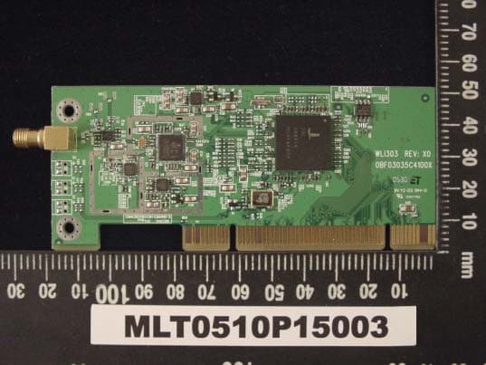
N7ZWLI303
Dec 01, 2005WIRELESS LAN 802.11/b,g
Equipment Class
DTS - Digital Transmission System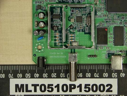
N7ZEC420
Oct 23, 2005CABLE MODEM
Equipment Class
JBP - Part 15 Class B Computing Device Peripheral
N7ZRT-710S
Jan 01, 2002Broadband Sharing Router
Equipment Class
JBP - Part 15 Class B Computing Device Peripheral