N7ZP100
Turbocomm Tech Inc.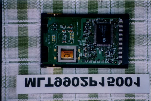
Click to zoom
Application Details
- Equipment Class
- JBP - Part 15 Class B Computing Device Peripheral
- Date of Grant
- Mar 23, 1999
- Application Purpose
- Original Equipment
- Date of Application
- Feb 09, 1999
- Company
- Turbocomm Tech Inc.
- Country
- Taiwan
Documents & Files
Document Text
Text extracted from the exhibit documents filed with the FCC. Open a document above to read the original.
Users Manual
1 Section One - Introduction This new series of modems represents a new generation of PC communication peripheral devices, combining high speed Data, Fax, Voice* , Full-Duplex Speakerphone* and SVD* (Simultaneous Voice and Data) functions into a single device. **56000 modem can even make your download speed from central ISP (Internat Service Provider) upto 56000bps. This high performance modem connects your computer to all popular modems and fax machines in use today. This manual provides installation and operation instructions for your modem. Also included in this manual are lists and descriptions of the standard AT command set, S-registers, and troubleshooting tips. Be certain to read Section Two - Installing The Modem thoroughly before performing the actual installation. 1.1 Modem Features and Compatibility Your modem is compatible with the following standards. • **K56flex TM (56Kbps down stream only) •V.80 (Video Ready Mode) • V.34 (33600 bps)• V.32bis (14400 bps) • V.32 (9600 bps)• V.22bis (2400 bps) • V.22 (1200 bps)• Bell 212A (1200 bps) • Bell 103 (300 bps)• V.17 (14400 bps FAX) • V.29 (9600 bps FAX)• V.27ter (4800 bps FAX) • V.21 Channel-2 (300 bps FAX)• V.42bis (data compression) • V.42 (error correction)• MNP 5 (data compression) • MNP 2-4 (error correction)• EIA/TIA 602 AT Command set • TIA/EIA 578 Class 1 Fax Command set •Plug and Play ISA spec V1.0a* Notes: * Voice, Speakerphone, SVD and PnP are optional features which may not be available on your modem. ** 56,000 download feature is for 56000 modem only. If your modem doesn't support those features, please disregard the relative section of the manual. The speed of 56Kbps limits to download from an ISP, while upload remains 33.6Kbps. Current FCC regulations, however, limit download speeds to 53Kbps. For peer-to-peer communication, the speed remains at 33.6Kbps. 2 1.2 Contents of Your Package • One modem•Communication software diskette(s) • One software manual• One telephone cable • One AC power adapter (external modem only) • Warranty Registration Card Notes: Please contact the place of purchase if any of the listed items are missing from your package. 1.3 Where To Go From Here If you have difficulties getting your modem to work, read Section 2.2.1 and Section 4 to find information on COM ports and IRQ's, as well as answers to frequently asked questions. Sections 5 through 10 contain material such as AT commands, S-register, and Result-codes to use as references when needed. We recommend thoroughly reading the software manual to become familiar with the functions and features provided by the communication software. The software manual includes detailed information on all com- mon modem functions. Understanding how the software works will help to provide many years of trouble-free modem operation. Additionally, you may also use any other communication software commercially available. If you have an external modem, proceed to Section 2.1 for installa- tion instructions. If installing an internal modem, proceed to Section 2.2 Section Two - Installing The Modem 2.1 External Modem Installation The following steps provide instructions for installing your external modem. You will also need a RS232 serial cable to make the connection to your computer. For IBM compatible computers equipped with a 25-pin serial port, you will need a standard 25-pin to 25-pin "straight-through" serial cable. If you have a 9-pin serial port on your PC, use a 9-pin to 25- pin "IBM AT" type serial cable. For Macintosh computers, use only a high speed Macintosh serial cable, which supports hardware flow control signals. 1. Turn off the computer. 2. Plug the male (25 pins) end of the serial cable into the connector marked RS-232 on the back of the modem (see Figure 2-1). 3. Plug the other end of the serial cable into your computer's serial port 3 (COMx; x=1,2,3... on IBM and compatible PCs). 4. Plug the telephone cable into the connector marked LINE on the back of the modem. 5. Plug the other end of the telephone cable into a telephone wall jack. 6. Make sure to verify the modem power switch is in the off position (located on the front panel). Plug the AC adapter's power cord into the connector marked POWER on the back of the modem. 7. Plug the transformer end of the AC adapter into a standard AC wall outlet 8. Optionally connect : (1) your telephone to the modem's PHONE connector. Lift the handset and listen for a dial tone to check for a working connection.(2) a speaker to the modem's SPK connector, and (3) a microphone to the modem's MIC connector. 9. Turn on the modem. The modem should perform a self-test, and then be ready for use. You may now turn on your computer. Note:The SPK and MIC jacks are optional feature which may not be available on your modem. Figure 2-1 External Modem MIC 4 2.1.1 Indicator Lights Your modem (external model only) features LED indicators on the front panel that report modem status: MR Modem ReadyOn when modem is ready to work TR Terminal ReadyOn when DTR signal is active SD Send DataOn when modem is transmitting data to remote modem RD Receive DataOn when modem is receiving data from remote modem OH Off HookOn when modem is off hook CD Carrier DetectOn when remote carrier has been detected RS Request to SendOn when RTS signal is active CS Clear to SendOn when CTS signal is active This completes the external modem installation. Proceed to Section 3 for information on installing and configuring your communication soft- ware. 2.2 Internal Modem Installation The following steps provide instructions for installing your internal modem. CAUTION: Before removing the cover from your computer, turn off and unplug the computer and all attached external peripherals. Prior to removing the modem from its antistatic bag, discharge any static electricity from your body by touching any metal surface. 1. Turn off the computer and unplug it from the AC outlet. 2. Remove the computer's cover, in accordance to its owner's manual. 3. Select any a…
Text truncated - open the document above for the full version.
Block Diagram
MAX LIGHT Report Number: MLT9902P15001 FCC ID: N7ZP100 Technology Lab
External Photos
MAX LIGHT Report Number: MLT9902P15001 FCC ID: N7ZP100 Technology Lab MAX LIGHT Report Number: MLT9902P15001 FCC ID: N7ZP100 Technology Lab MAX LIGHT Report Number: MLT9902P15001 FCC ID: N7ZP100 Technology Lab MAX LIGHT Report Number: MLT9902P15001 FCC ID: N7ZP100 Technology Lab
ID Label/Location Info
MAX LIGHT Report Number: MLT9902P15001 FCC ID: N7ZP100 Technology Lab Label Format: Label Position: This device complies with Part15 of the FCC Rules. Operation is subject to the following two conditions: (1) This device may not cause harmful interference,and (2) This device must accept any interference received ,including. Interference that may cause undesired operation. Model: P100 / M1-P100 / M2-P100 / M3-P100 / M4-P100 FCC ID: N7ZP100 MADE IN TAIWAN Equipment Lable 3CMX2CM Rear View
Schematics
MAX LIGHT Report Number: MLT9902P15001 FCC ID: N7ZP100 Technology Lab MAX LIGHT Report Number: MLT9902P15001 FCC ID: N7ZP100 Technology Lab
Test Report
Product : 56K Data / Fax Voice PCMCIA Modem Manufacture : TURBOCOMM TECH. INC. FCC ID : N7ZP100 Model : P100 / M1-P100 / M2-P100 / M3-P100 / M4-P100 Report No. : MLT9902P15001 Test Date : 02/08/1999 Test By Max Light Technology Co.,Ltd. Room 5, 8F, No.125, Section 3 Roosevelt Road, Taipei, Taiwan., R.O.C. Tel: 886-2-2363-2447 Fax: 886-2-2363-2597 MAX LIGHT MEASUREMENT REPORT Page:2/21 Report Number: MLT9902P15001FCC ID: N7ZP100 Technology Lab Table of Contents : I. General 4. II. Conducted Emissions Requirements 9. III. Radiated Emissions Requirements 14. Appendix I (EUT Test Setup) 20. MAX LIGHT MEASUREMENT REPORT Page:3/21 Report Number: MLT9902P15001FCC ID: N7ZP100 Technology Lab CERTIFICATION We here by verify that : The test data, data evaluation, test procedures and equipment configurations shown in this report were made in accordance with the procedures given in ANSI C63.4-1992. All test were conducted by MLT(Max Light Technology Co.,Ltd) Room 5, 8F, No.125, Section 3 Roosevelt Road, Taipei, Taiwan, R.O.C Also, we attest to the accuracy of each. We further submit that the energy emitted by the sample EUT tested as described in the report is in compliance with Class B radiated and conducted emission limit of FCC Rules Part 15 Subpart B. EUT: 56K Data / Fax Voice PCMCIA Modem Applicant: TURBOCOMM TECH. INC. 4F-2, No.171, Sung-Tech Road, Taipei ,Taiwan Manufacturer: CASTLENET TECHNOLOGY INC. No.130, Wu-Kung Rd., Wu-Ku Hsiang Taipei Hsien ,Taiwan Model No: P100 / M1-P100 / M2-P100 / M3-P100 / M4-P100 FCC ID: N7ZP100 Prepared by :Approved by : Country Huang Roger Chen MAX LIGHT MEASUREMENT REPORT Page:4/21 Report Number: MLT9902P15001FCC ID: N7ZP100 Technology Lab I. GENERAL 1.1 Introduction The following measurement report is submitted on behalf of TURBOCOMM TECH. INC. In support of a Class B Digital Device certification in accordance with Part2 Subpart J and Part 15 Subpart A And B of the Commission’s and Regulations. 1.2 Description of EUT EUT: 56K Data / Fax Voice PCMCIA Modem Applicant: TURBOCOMM TECH. INC. . 4F-2, No.171, Sung-Tech Road, Taipei ,Taiwan Manufacturer: CASTLENET TECHNOLOGY INC. No.130, Wu-Kung Rd., Wu-Ku Hsiang Taipei Hsien ,Taiwan Model No: P100 / M1-P100 / M2-P100 / M3-P100 / M4-P100 FCC ID : N7ZP100 Power Type: Powered by PC Phone Cable: RJ-11Cx1(Nonshielded, 8’ long ,Plastic hoods) During testing the EUT was operated at Tx or Rx mode for each emission measured. This was done in order to ensure that maximum emission levels were attained. MAX LIGHT MEASUREMENT REPORT Page:5/21 Report Number: MLT9902P15001FCC ID: N7ZP100 Technology Lab 1.3 Description of Support Equipment In order to construct the minimum system which required by the ANSI C63.4-1991, following equipments were used as the support units. Computer: ACER Model No.: 500DX Serial No.: 8145B01S018210001FM FCC ID: FCC(DOC) Keyboard: SOLID YEAR Model No.: ACK-231 Serial No.: 5AHGS72 FCC ID: L2BACEKEY231 Monitor: COMPAQ Model No.: 303U Serial No.: 704AG19TG099 FCC ID: BJMCM14UH Mouse: COMPAQ Model No.:196694-301 Serial No.:1SH67CHE03360 FCC ID: EMJMUSJJ Printer: PANASONIC Model No.: KX-P1080I Serial No.: 7CKAKE98933 FCC ID: ACJ5Z6KX-P10801 PSTN Simulator: MLT Model No.: 1101 Serial No.: N/A MAX LIGHT MEASUREMENT REPORT Page:6/21 Report Number: MLT9902P15001FCC ID: N7ZP100 Technology Lab Speaker: KAKA Model No.: 2K-A01 Serial No.: 189665 Microphone: Ever Power Model No.: TC-944 Serial No.: N/A Modem: Askey (External Fax / Data Modem) Model No.: WS1414SV Serial No.: IAH-10811 FCC ID: H8N1414VE MAX LIGHT MEASUREMENT REPORT Page:7/21 Report Number: MLT9902P15001FCC ID: N7ZP100 Technology Lab 1.4 Configuration of System Under Test During testing the EUT(Data / Fax PCMCIA Modem card) install in the Notebook’s PCMCIA slot. So there is no need for additional I/O card. A VGA monitor was connected to the VGA port of Notebook and a keyboard was connected to the USB port of Notebook. A mouse was connected to the PS2 port and a printer was connected to the parallel port. There is one serial port. A external modem connected the serial port and the external modem connected with two unterminated telephone cables on the line and phone jack. the RJ-11 cable of EUT was connected to a simulator of PSTN. And the Notebook’s Speaker Jack and Notebook’s Microphone Jack were connected with a small microphone and a external speaker. Power Supply Printer MouseEUT Keyboard RJ11C Cables Adapter RS-232 Speaker Mic To PSTN Modem Notebook RS-232 PS2 Cable USB Cable Monitor MAX LIGHT MEASUREMENT REPORT Page:8/21 Report Number: MLT9902P15001FCC ID: N7ZP100 Technology Lab 1.5 Test Procedure All measurements contained in this report were performed according to the techniques described in Measurement procedure ANSI C63.4-1992 "Measurement of unIntentional Radiators." 1.6 General Test Condition The conditions under which the EUT operates were varied to determine their effect on the equipment's emission characteristics. The final configuration of the test system and the mode of operation used during these tests was chosen as that which produced the highest emission levels. However, only those conditions which the EUT was considered likely to encounter in normal use were investigated. The system's radiated and conducted emissions were investigated while the computer alternately transferred data to the EUT as well as to the monitor and printer. Using a test program which sent a continuous stream of “H” characters to monitor and transferred data to and from the EUT was proven to worst case emissions. The system's physical layout and cabling was randomly arranged to ensure that maximum emission levels were attained. MAX LIGHT MEASUREMENT REPORT Page:9/21 Report Number: MLT9902P15001FCC ID: N7ZP100 Technology Lab II. Conducted Emissions Requirements 2.1 General & Setup : The power line conducted emission measurements were performed in a shielded enclosure. The EUT was assembled on a wooden table which is 80 centimeters high, was placed 40 centimeters …
Text truncated - open the document above for the full version.
Contact Information
Applicant
Ken Hsu(Senior Engineer)
Technical Contact
Max Light Technology Co.,LtdCountry Huang
[email protected]886-2-26633486
P.O.Box 5-86,Shen Keng · Taiwan
Non-Technical Contact
Max Light Technology Co.,LtdCountry Huang
[email protected]886-2-26633486
Technical Specifications
| # | Rule Parts | Frequency Range | Power Output | Tolerance |
|---|---|---|---|---|
| 1 | 15B | - | - | % |
Other Applications from Turbocomm Tech Inc.

N7ZRT-900W
Jun 07, 2006Wireless AP
Equipment Class
DTS - Digital Transmission System
N7ZWVM-1101
May 11, 2006Wireless Video Module
Equipment Class
NII - Unlicensed National Information Infrastructure TX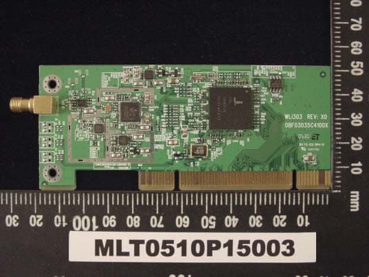
N7ZWLI303
Dec 01, 2005WIRELESS LAN 802.11/b,g
Equipment Class
DTS - Digital Transmission System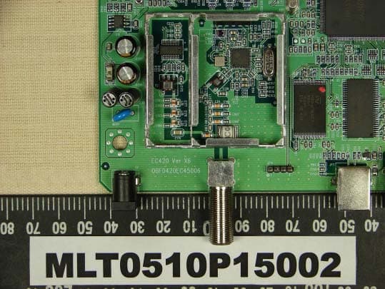
N7ZEC420
Oct 23, 2005CABLE MODEM
Equipment Class
JBP - Part 15 Class B Computing Device Peripheral
N7ZRT-710S
Jan 01, 2002Broadband Sharing Router
Equipment Class
JBP - Part 15 Class B Computing Device Peripheral