N7ZRT-710SOHO Router / SofaBox
Turbocomm Tech Inc.
Click to zoom
Application Details
- Equipment Class
- JBP - Part 15 Class B Computing Device Peripheral
- Date of Grant
- Sep 12, 2001
- Application Purpose
- Original Equipment
- Date of Application
- Sep 12, 2001
- Equipment Note
- SOHO Router / SofaBox
- Company
- Turbocomm Tech Inc.
- Country
- Taiwan
Documents & Files
Document Text
Text extracted from the exhibit documents filed with the FCC. Open a document above to read the original.
Users Manual
Heritage Series ADSL Bridge/ Router RT 710 Broadband Sharing Router User’s Manual Jly. 2001 Heritage Series ADSL Bridge/ Router Copyright All rights reserved. No part of this document may be reproduced in any form or by any means without written permission from the product manufacturer. Changes are periodically made to the information in this document. They will be incorporated in subsequent editions. The product manufacturer may make improvements and/or changes in the product described in this document at any time. Heritage Series ADSL Bridge/ Router Contents Table of Contents Chapter 1 Product Overview 1 1.1 Overview 1 1.2 Features and Compatibility 2 1.3 What’s in the package? 3 1.4 Important Rules for Safe Operation 4 1.5 Front Panel 7 1.6 Real Panel 8 Chapter 2 Network Set-up 9 2.1 Preparation for network installation 10 2.2 Network installation 11 Chapter 3 System Configuration 13 3.1 Get your Broadband Sharing Router Ready 14 3.2 Winsows 95/98 setting for Ethernet LAN connection 15 3.2.1 Check TCP/IP protocol 15 3.2.2 TCP/IP installation 17 3.2.3 TCP/IP setting 19 3.3 MAC OS TCP/IP setting 21 3.4 Basic Configuration 22 3.4.1 Sharing a Cable Modem connection (default) 22 3.4.2 Sharing an always-on ADSL connection 25 3.4.3 Sharing a dial up ADSL connection 27 3.4.4 Compart your network 29 3.5 Advanced Configuration 30 3.5.1 Device Information 30 3.5.2 WAN Port Setting 31 3.5.3 LAN Port Setting 32 3.5.4 IP masqurade setting 34 3.5.5 Firewall setting 35 3.5.6 Firmware upgrade 36 3.5.7 PPPoE setting 37 Contents Appendix Appendix A Glossary A1 Appendix B Product Specifications A8 Appendix C Troubleshooting A10 Appendix D Government Compliance Notices A13 Heritage Series ADSL Bridge/ Router 1 Introduction Chapter 1 Introduction 1.1 Product Overview The RT710 Broadband Sharing Router is an easy installation Router to share a single xDSL or Cable Modem broadband connection with your family members or colleagues. With the minimum hardware investment, you can easily sharing your broadband connection direct to 4 computers with build-in 10/100Base-T stackable switching HUB. More local connections (253) can be expanded with dumb or switching HUB distribution. The RT710 Broadband Sharing Router is also a LAN-to-LAN Router and can easily divide your local networks into a separated and secured section. With IP filtering and password protection, you can remain your network in private and safe. 2 Introduction 1.2 Features and Compatibility The RT710 Broadband Sharing Router provides the following features: Protocol • DHCP: RFC1541 (Client and Server Function) • IP: RFC791 • ARP: RFC826 • UDP: RFC768 • TCP: RFC793 • RIP: RFC 1058 • PPP: PPPoE support for ADSL • NAT/IP Masqurade Networking Management • Web based configuration through Ethernet interfaces • Syslog for recording connection log • Telnet and TFTP for firmware update and configuration file backup and restore Firewall • Packet Filtering and Port Filtering for controlled access to and from your network Heritage Series ADSL Bridge/ Router 3 Introduction 1.3 What’s in the package? !" One RT710 Broadband Sharing Router !" One 9VAC Adaptor !" One 10Base-T Ethernet straight-through Cable !" One User Guide All packages have been checked carefully for their completeness and functionality before shipped. Please contact the place of purchase if any of the above listed items is missing or damaged. If you encountered any difficulty in using this product while all the above items are complete, please refer to Appendix C for Troubleshooting information before making the decision to return your Broadband Sharing Router to your dealer. 4 Introduction 1.4 Important Rules for Safe Operation In addition to the careful attention devoted to quality standards on the manufacture of your Router, safety is a major factor in the design of every product. However, safety is your responsibility, too. This section lists important information that will help assure your enjoyment and proper use of the Router and accessory equipment. Please read them carefully before operation and using your Modem. !"Read and Follow Instructions – you should read all the safety and operating instructions before operating the Router. !" Retain Instructions – You should save all the safety and operating instructions, for your future reference. !" Heed Warning – Comply with all warnings on the products and in the operating instructions. !" Check Power Sources – Operate this product only from the type of power source indicated on the product’s marking label. If you are not sure of the type of power supplied to your home, consult your dealer or local power company. !" Be Careful of Overloading – Do not overload wall outlets or extension cords, as this can result in a risk of fire or electric shock. Overloaded AC outlets, extension cords, frayed power cords, damaged or cracked wire insulation, and broken plugs are dangerous. They may result in a shock or fire hazard. Periodically examine the cord, and if its appearance indicates damage or deteriorated insulation, have it replaced by your service technician. !" Protect Power Cords – Route power supply cords so that they are not likely to be walked on or pinched by items placed upon or against them. Pay particular attention to cords where they are attached to plugs and convenience receptacles, and examine the point where they exit from the product. !" Check Ventilation – Slots and openings in the enclosure are provided for ventilation to ensure reliable operation of the product and to protect it from overheating. Do not block or cover these openings. Never block these openings by placing the product on a bed, sofa, rug, or other similar surface. Never place this product near or over a radiator or heat register, or any other heat source (including amplifiers). Do not place this product in a Heritage Series ADSL Bridge/ Router 5 Introduction built-in installation, such as a bookcase or equipment rack, unless you provide proper ventilation. !" Do Not …
Text truncated - open the document above for the full version.
Block Diagram
5 5 4 4 3 3 2 2 1 1 DD CC BB AA CPU(3927) FLASH(2M/Boot) FLASH(64M) SDRAM(128M*2) MAC(RTL8100)MAC(RTL8100) PCI BUS 1 PORT(WAN) POWER(3.3V/2.5V) LED DISPLAY RT-710 4 PORT(LAN) SWITCH(8995E) 8.33MHz X'TAL 25MHz X'TAL 25MHz X'TAL 25MHz X'TAL {Doc}X1 RT-710 A 11Wednesday, August 15, 2001 Title SizeDocument NumberRev Date:Sheet of
External Photos
MAX LIGHT Report Number: MLT0108P15001 FCC ID: N7ZRT-710 Technology Lab MAX LIGHT Report Number: MLT0108P15001 FCC ID: N7ZRT-710 Technology Lab
ID Label/Location Info
MAX LIGHT Report Number: MLT0108P15001 FCC ID: N7ZRT-710 Technology Lab Label Format: Label Position: This device complies with Part15 of the FCC Rules. Operation is subject to the following two conditions: (1) This device may not cause harmful interference,and (2) This device must accept any interference received ,including. Interference that may cause undesired operation. Model : RT-710 / SBX-133LHE-1 FCC ID : N7ZRT-710 MADE IN TAIWAN Equipment Lable 3.5CMX6CM Rear View
Internal Photos
MAX LIGHT Report Number: MLT0108P15001 FCC ID: N7ZRT-710 Technology Lab MAX LIGHT Report Number: MLT0108P15001 FCC ID: N7ZRT-710 Technology Lab MAX LIGHT Report Number: MLT0108P15001 FCC ID: N7ZRT-710 Technology Lab
Test Report
Product : SOHO ROUTER / SofaBox Applicant : TURBOCOMM TECH. INC. FCC ID : N7ZRT-710 Model : RT-710 / SBX-133LHE-1 Report No. : MLT0108P15001 Test Date :August 15,2001 Test By Max Light Technology Co.,Ltd. Room 5, 8F, No.125, Section 3 Roosevelt Road, Taipei, Taiwan., R.O.C. Tel: 886-2-2363-2447 Fax: 886-2-2363-2597 T T h h e e t t e e s s t t r r e e p p o o r r t t c c o o n n s s i i s s t t s s o o f f 2 2 1 1 p p a a g g e e s s i i n n t t o o t t a a l l . . I I t t m m a a y y b b e e d d u u p p l l i i c c a a t t e e d d c c o o m m p p l l e e t t e e l l y y f f o o r r l l e e g g a a l l u u s s e e w w i i t t h h t t h h e e a a l l l l o o w w a a n n c c e e o o f f t t h h e e a a p p p p l l i i c c a a n n t t . . I I t t s s h h a a l l l l n n o o t t b b e e r r e e p p r r o o d d u u c c e e d d e e x x c c e e p p t t i i n n f f u u l l l l , , w w i i t t h h o o u u t t t t h h e e w w r r i i t t t t e e n n a a p p p p r r o o v v a a l l o o f f o o u u r r l l a a b b o o r r a a t t o o r r y y . . MAX LIGHT MEASUREMENT REPORT Page: 2/212 Report Number: MLT0108P15001 FCC ID: N7ZRT-710 Technology Lab Table of Contents : I. General 4. II. Conducted Emissions Requirements 9. III. Radiated Emissions Requirements 14 Appendix I (EUT Test Setup) 20 MAX LIGHT MEASUREMENT REPORT Page: 3/212 Report Number: MLT0108P15001 FCC ID: N7ZRT-710 Technology Lab CERTIFICATION We here by verify that : The test data, data evaluation, test procedures and equipment configurations shown in this report were made in accordance with the procedures given in ANSI C63.4-1992. All test were conducted by MLT(Max Light Technology Co.,Ltd) Room 5, 8F, No.125, Section 3 Roosevelt Road, Taipei, Taiwan, R.O.C Also, we attest to the accuracy of each. We further submit that the energy emitted by the sample EUT tested as described in the report is in compliance with Class B radiated and conducted emission limit of FCC Rules Part 15 Subpart B. EUT : SOHO ROUTER / SofaBox Applicant : TURBOCOMM TECH. INC. 4F-2, No.171, Sung- Tech Road, Taipei ,Taiwan Manufacturer : TURBOCOMM TECH. INC. No.369,Sec.3 Chun Cheng East Road, Wu Chuan Tsun,Ta Yuan Hsiang,Tao Yaun Hsien,Taiwan,R.O.C. Model No : RT-710 / SBX-133LHE-1 FCC ID : N7ZRT-710 Prepared by : Approved by : Country Huang Roger Chen MAX LIGHT MEASUREMENT REPORT Page: 4/212 Report Number: MLT0108P15001 FCC ID: N7ZRT-710 Technology Lab I. GENERAL 1.1 Introduction The following measurement report is submitted on behalf of TURBOCOMM TECH. INC. In support of a Class B Digital Device certification in accordance with Part2 Subpart J and Part 15 Subpart A And B of the Commission’s and Regulations. 1.2 Description of EUT EUT : SOHO ROUTER / SofaBox Applicant : TURBOCOMM TECH. INC. 4F-2, No.171, Sung- Tech Road, Taipei ,Taiwan Manufacturer : TURBOCOMM TECH. INC. No.369,Sec.3 Chun Cheng East Road, Wu Chuan Tsun,Ta Yuan Hsiang,Tao Yaun Hsien,Taiwan,R.O.C. Model No : RT-710 / SBX-133LHE-1 FCC ID : N7ZRT-710 Power Type : Powered by AC Adaptor (9V [email protected]) Ethernet Cable : RJ-45 x4 (Nonshielded, 6’ long ,Plastic hoods)/LAN Ethernet Cable : RJ-45 x1 (Nonshielded, 6’ long ,Plastic hoods)/WAN During testing the EUT was operated at Tx or Rx mode for each emission measured(P.S Run “Ping (IP Address) –T –L 1000” comment in Dos Mode). This was done in order to ensure that maximum emission levels were attained. MAX LIGHT MEASUREMENT REPORT Page: 5/212 Report Number: MLT0108P15001 FCC ID: N7ZRT-710 Technology Lab 1.3 Description of Support Equipment In order to construct the minimum system which required by the ANSI C63.4-1991, following equipments were used as the support units. Computer : IBM Model No. : 16W Serial No. : BNC345M FCC ID : FCC(DOC) Keyboard : IBM Model No. : KB-9930 Serial No. : 09N5395 FCC ID : FCC(DOC) Monitor : IBM Model No. : 10L6145 030 Serial No. : 23-092079 FCC ID : ARSCM569N Mouse : IBM Model No. : 0180-05N Serial No. : 23-092079 FCC ID : JNZ211220 Printer : PANASONIC Model No. : KX-P1080I Serial No. : 7CKAKE98933 FCC ID : ACJ5Z6KX-P10801 Ethernet Card : 3COM Model No. : 3C905C-TX Serial No. : HDUD984803 FCC ID : FCC DOC MAX LIGHT MEASUREMENT REPORT Page: 6/212 Report Number: MLT0108P15001 FCC ID: N7ZRT-710 Technology Lab Ethernet Card : DELTA Model No. : NE2000 Ethernet Adapter Serial No. : 4712544 FCC ID : FCC DOC Modem : Askey (External Fax / Data Modem) Model No. : WS1414VE Serial No. : IAH-10811 FCC ID : H8N1414VE MAX LIGHT MEASUREMENT REPORT Page: 7/212 Report Number: MLT0108P15001 FCC ID: N7ZRT-710 Technology Lab 1.4 Configuration of System Under Test During testing the EUT(SOHO ROUTER / SofaBox )’s WAN / L1&L3&L4(LAN) Ethernet port connected to the Remote Ethernet and L2 port were connected Ethernet port of IBM computer. So there is need for additional Ethernet card. A mouse was connected to the mouse port of IBM PC. and A keyboard was connected to the mouse port of IBM PC. And a printer was connected to the parallel port. A external modem connected the serial port and the external modem connected with two unterminated telephone cables on the line and phone jack. TEST SITE Power Supply PC Monitor Printer Modem Keyboard Mouse EUT RJ11C Cables RS-232 RS-232 To Other Ethernet Card UTP Cable MAX LIGHT MEASUREMENT REPORT Page: 8/212 Report Number: MLT0108P15001 FCC ID: N7ZRT-710 Technology Lab 1.5 Test Procedure All measurements contained in this report were performed according to the techniques described in Measurement procedure ANSI C63.4-1992 "Measurement of unIntentional Radiators." 1.6 General Test Condition The conditions under which the EUT operates were varied to determine their effect on the equipment's emission characteristics. The final configuration of the test system and the mode of operation used during these tests was chosen as that which produced the highest emission levels. However, only those conditions which the EUT was considered likely to encounter in normal use were investigated. The system's radiated and conducted emi…
Text truncated - open the document above for the full version.
Test Setup Photos
MAX LIGHT MEASUREMENT REPORT Page: 15/212 Report Number: MLT0108P15001 FCC ID: N7ZRT-710 Technology Lab 3.3 Test Configuration: Front View of The Test Configuration MAX LIGHT MEASUREMENT REPORT Page: 16/212 Report Number: MLT0108P15001 FCC ID: N7ZRT-710 Technology Lab Rear View of The Test Configuration
Test Setup Photos
MAX LIGHT MEASUREMENT REPORT Page: 10/212 Report Number: MLT0108P15001 FCC ID: N7ZRT-710 Technology Lab 2.3 Test Configuration: Front View of The Test Configuration MAX LIGHT MEASUREMENT REPORT Page: 11/212 Report Number: MLT0108P15001 FCC ID: N7ZRT-710 Technology Lab Rear View of The Test Configuration
Contact Information
Applicant
Ken Hsu(Senior Engineer)
Test Firm
Max Light Technology Co., Ltd.Jesse Tien
Technical Specifications
| # | Rule Parts | Frequency Range | Power Output |
|---|---|---|---|
| 1 | 15B | - | - |
Other Applications from Turbocomm Tech Inc.

N7ZRT-900W
Jun 07, 2006Wireless AP
Equipment Class
DTS - Digital Transmission System
N7ZWVM-1101
May 11, 2006Wireless Video Module
Equipment Class
NII - Unlicensed National Information Infrastructure TX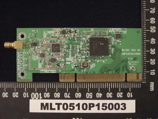
N7ZWLI303
Dec 01, 2005WIRELESS LAN 802.11/b,g
Equipment Class
DTS - Digital Transmission System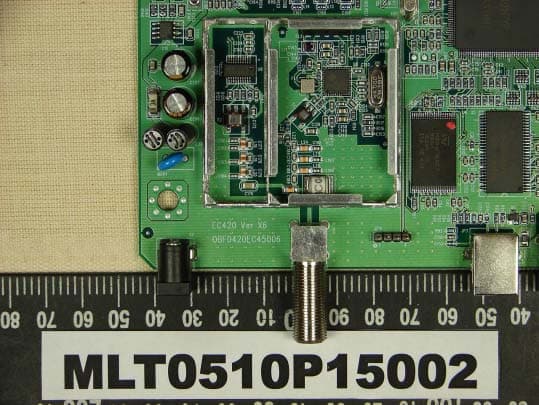
N7ZEC420
Oct 23, 2005CABLE MODEM
Equipment Class
JBP - Part 15 Class B Computing Device Peripheral
N7ZRT-710S
Jan 01, 2002Broadband Sharing Router
Equipment Class
JBP - Part 15 Class B Computing Device Peripheral