NAHAS3501SECURITY TRANSMITTER
Autostart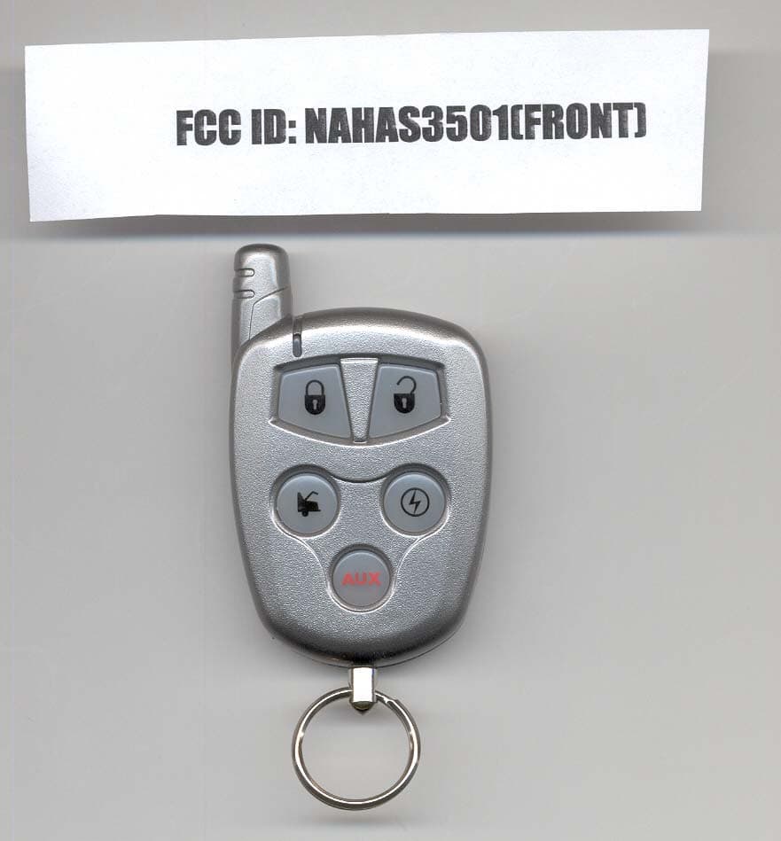
Click to zoom
Application Details
- Equipment Class
- DSC - Part 15 Security/Remote Control Transmitter
- Date of Grant
- Jan 24, 2007
- Application Purpose
- Original Equipment
- Date of Application
- Jan 24, 2007
- Equipment Note
- SECURITY TRANSMITTER
- Frequency Range
- 433.90000000 - 433.90000000
- Company
- Autostart
- Country
- Canada
Documents & Files
Document Text
Text extracted from the exhibit documents filed with the FCC. Open a document above to read the original.
Users Manual
DOC: 1.00 (i) – January 4, 2007 DL Lp Manufactured in Canada by Autostart TWO-WAY LED AUTOMATIC TRANSMISSION REMOTE STARTER AS-2310TW-FM User Guide WARNING It is the responsibility of the vehicle operator to ensure their vehicle is parked in a safe and responsible manner. 1. When leaving the vehicle, it is the user’s responsibility to ensure that the gearshift lever is in “Park” in order to avoid accidents upon remote starting. 2. It is the user's responsibility to ensure that the remote starter is disabled or put into valet mode before servicing. FCC/IC Notice: This device complies with Part 15 of the FCC Rules, and RSS-210 of the IC rules. Operation is subject to the following two conditions: (1) this device may not cause harmful interference, and (2) this device must accept any interference received, including interference that may cause undesired operation. User Guide P. 2 The manufacturer is not responsible for any radio or TV interference caused by unauthorized modifications to this equipment. Such modifications could void the user's authority to operate the equipment. P. 3 User Guide AS-1525 SH Table of Contents Introduction........................................... 3 Using the Remote Control ................... 4 Vehicle Presets ..................................... 4 Heater & Heated Seat ................................ 4 Windshield Wipers & Radio & Headlights .. 4 Arming the Starter Kill.......................... 5 Remote-Starting Your Vehicle ............. 5 Remote-starting.......................................... 5 Driving Off .................................................. 5 Remote Starter Features ...................... 5 Idle Mode.................................................... 5 Valet Modes ............................................... 6 Ignition Valet ................................... 6 Remote Valet Mode ........................ 6 Panic Mode ................................................ 6 Quick Lockout TM ......................................... 7 Cold Weather Mode ................................... 7 Extended Run Time ................................... 7 Feature Confirmation Chart ................. 8 Advanced Features: Installation- programmable Options ........................ 8 Remote Door Locks ................................... 8 Priority Door Access................................... 8 Ignition-Controlled Door Locks ................... 8 Ignition Re-lock........................................... 8 Secure Lock................................................ 9 Remote Trunk Release .............................. 9 The Starter Kill and the Anti-grind Feature. 9 Safe Start.................................................... 9 Valet Modes................................................ 9 Valet Mode Using the Valet Switch (if installed) ......................................... 9 “Home Valet TM ” Mode................................. 9 Turbo Mode .............................................. 10 Engine Run Time...................................... 10 Flashing LED ............................................ 10 Multi-car Operation ................................... 10 Multi-Level Features (default state)..... 11 Vehicle Status Request ...................... 12 Status Request When the Engine IS NOT Running .................................................... 12 Status Request When the Engine is Running .................................................... 13 Troubleshooting Transmitting Range13 Diagnostics – Parking Light Flash Table .................................................... 15 Introduction This is a state-of-the-art remote starter system. The system is packed with advanced features such as priority access to the driver’s door (commodity features) and the safe start children safety feature. With many an advanced function, this product will satisfy any one your expectations from high-end commodity and security systems, without neglecting any standard feature commonly offered by entry-level starters. P. 4 User Guide Using the Remote Control Your remote starter is equipped with a 5-button multi-channel remote control. It can operate two independent vehicles equipped with a remote starter (see Multi-car operation section on page 10). The functions of the transmitter are as follows: Picture serves as example only. For certain vehicles: • Pressing and holding the LOCK button for more than 3 seconds will lock all doors and will send a constant pulse as long as the LOCK button is held down (maximum of 15 seconds). This constant pulse can be configured to activate certain functionalities such as rolling up the windows – Please refer to your installer to see if your vehicle is compatible with this option. • Pressing and holding the UNLOCK button for more than 3 seconds will unlock all doors and will send a constant pulse as long as the UNLOCK button is held down (maximum of 15 seconds). This constant pulse can be configured to activate certain functionalities such as rolling down the windows – Please refer to your installer to see if your vehicle is compatible with this option. Vehicle Presets Heater & Heated Seat When leaving the vehicle it is recommended to preset the accessory controls in preparation for the next remote start. Settings for the blower motor (fan), front and rear, as well as heated seats (if equipped) should not be left on HIGH. It is recommended to leave the settings on LOW or MEDIUM instead. Windshield Wipers & Radio & Headlights Certain vehicles require the radio and / or windshield wiper and / or headlight circuits to become energized while running under remote start. When leaving the vehicle you must ensure that the windshield wiper and headlight switches are OFF. Leaving the headlight switch ON on certain types of vehicles could cause them to remain ON even after remote starter shut down, resulting in a dead battery. LED #2 LED #4 LED #1 LED #3 Transmitter Part Number: ASRF3501 User Guide P. 5 Arming the Starter Kill The starte…
Text truncated - open the document above for the full version.
Cover Letter(s)
Autostart 5764 Pare Montreal, Quebec H4P 2M2 Tel: (514)738-9750 Fax: (514)738-4365 December 12, 2006 Federal Communications Commission Authorization and Evaluation Division Confidentiality Request regarding application for certification of FCC ID:NAHAS3501 Pursuant to sections 0.457 and 0.459 of the Commission's Rules, we herby request confidential treatment accompanying this application as outlined below: - ASRF3501_Schematic.pdf - ASRF3501_Block.pdf - ASRF3501_Circuit_Description.pdf The above materials contain trade secrets and proprietary information not customarily released to the public. The public disclosure of these materials may be harmful to the applicant and provide unjustified benefits to its competitors. The applicant understands that pursuant to section 0.457 of the rules, disclosure of this application and all accompanying documentation will not be made before the date of the Grant for this application. Sincerely, RJP
External Photos
AUTOSTART FCC ID: NAHAS3501 EXTERNAL PHOTOS
Internal Photos
AUTOSTART FCC ID: NAHAS3501 INTERNAL PHOTOS
Test Report
Tuned Frequency MHz Emission Frequency MHz * Meter Reading dBuV Ant. Polarity Coax Loss dB Correction Factor dB Duty Cycle Factor dB Field Strength dBuV/m Mar gin dB 433.9 433.90 55.8 H 1.23 16.62 5.10 68.55 12.27 433.9 433.90 60.3 V 1.23 16.18 5.10 72.61 8.21 433.9 867.80 6.2 H 1.93 22.96 5.10 25.99 34.83 433.9 867.80 6.6 V 1.93 22.40 5.10 25.83 34.99 433.9 1,301.80 ** 13.7 H 2.34 28.00 5.10 38.94 15.06 433.9 1,301.80 ** 14.9 V 2.34 28.00 5.10 40.14 13.86 433.9 1,735.70 14.5 V 2.69 29.70 5.10 41.79 19.04 433.9 1,735.70 14.7 H 2.69 29.70 5.10 41.99 18.84 433.9 2,169.50 8.0 V 3.02 31.94 5.10 37.86 22.97 433.9 2,169.50 8.5 H 3.02 31.94 5.10 38.36 22.47 433.9 2,603.40 7.7 H 3.32 32.77 5.10 38.69 22.13 433.9 2,603.40 11.4 V 3.32 32.77 5.10 42.39 18.43 433.9 3,037.30 8.1 H 3.63 33.39 5.10 40.02 20.80 433.9 3,037.30 9.1 V 3.63 33.39 5.10 41.02 19.80 433.9 3,471.20 7.3 V 4.02 33.31 5.10 39.53 21.29 433.9 3,471.20 7.5 H 4.02 33.31 5.10 39.73 21.09 433.9 3,905.10 ** 8.8 V 4.41 33.79 5.10 41.90 12.10 433.9 3,905.10 ** 8.8 H 4.41 33.79 5.10 41.90 12.10 433.9 4,339.00 ** 7.8 H 4.67 34.44 5.10 41.81 12.19 433.9 4,339.00 ** 7.8 V 4.67 34.44 5.10 41.81 12.19
Test Report
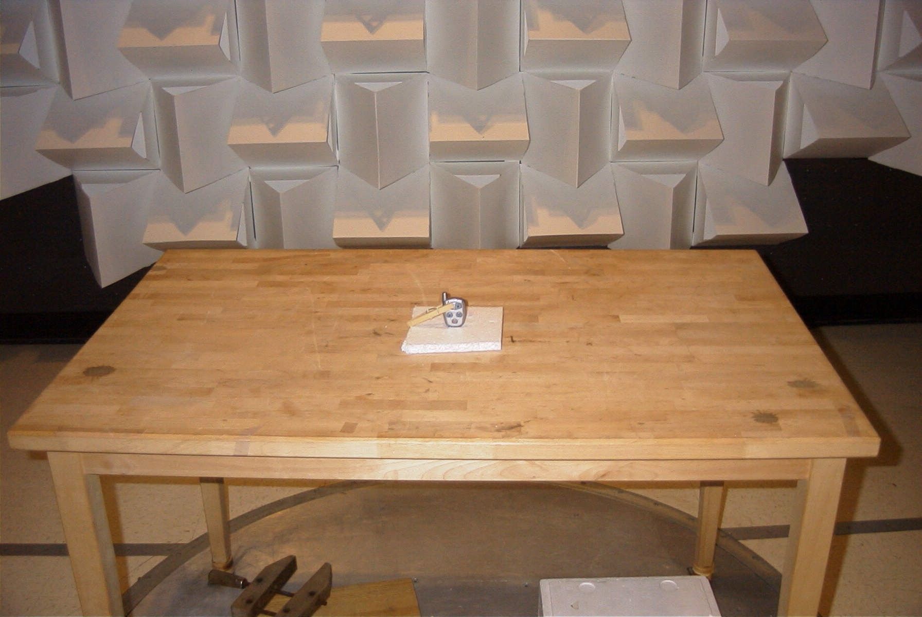
FCC TEST REPORT PART 15.231 APPLICANT AUTOSTART ADDRESS 5764 PARE MONTREAL QUEBEC H4P 2M2 CANADA FCC ID NAHAS3501 MODEL NUMBER AS3501 PRODUCT DESCRIPTION SECURITY TRANSMITTER DATE SAMPLE RECEIVED 12/14/2006 DATE TESTED 12/18/06 TESTED BY RICHARD BLOCK APPROVED BY MARIO DE ARANZETA TIMCO REPORT NO. 3384AUT6TestReport.doc TEST RESULTS PASS FAIL TOTAL PAGES THE ATTACHED REPORT SHALL NOT BE REPRODUCED EXCEPT IN FULL WITHOUT THE WRITTEN APPROVAL OF TIMCO ENGINEERING, INC. 849 NW STATE ROAD 45 NEWBERRY, FL 32669 USA PH: 888.472.2424 OR 352.472.5500 FAX: 352.472.2030 EMAIL: [email protected] HTTP://WWW.TIMCOENGR.COM APPLICANT: AUTOSTART FCC ID: NAHAS3501 REPORT: A\AUTOSTART_NAH\3384AUT6\3384AUT6TestReport.doc Page 2 of 13 TABLE OF CONTENTS GENERAL INFORMATION......................................................... 3 COMPLIANCE WITH PART 15.231(a)........................................... 4 EMC EQUIPMENT LIST.......................................................... 5 TEST PROCEDURE............................................................ 6 RADIATION INTERFERENCE................................................... 7 CALCULATION OF DUTY CYCLE................................................ 9 OCCUPIED BANDWIDTH....................................................... 11 TEST SET UP PHOTO.......................................................... 13 APPLICANT: AUTOSTART FCC ID: NAHAS3501 REPORT: A\AUTOSTART_NAH\3384AUT6\3384AUT6TestReport.doc Page 3 of 13 GENERAL INFORMATION EUT Specification The test results relate only to the items tested. FCC ID NAHAS3501 Model Number AS3501 Product Description SECURITY TRANSMITTER Operating Frequency 433.94MHz Primary Power 3VDC EUT Power Secondary Power N/A Prototype Pre-Production Test Item Production Fixed Mobile Type of Equipment Portable Test standards FCC Part 15 Subpart C and ANSI C63.4-2003 Modification to the DUT None Test exercise The EUT was set in continuous transmit mode Test Facility Timco Engineering Inc. 849 NW State Road 45 Newberry, FL 32669. Receiver The receiver portion of this system has been tested and meets all of the FCC requirements per FCC rules Part 15.109. A report was issued and a copy of this report is available upon request. APPLICANT: AUTOSTART FCC ID: NAHAS3501 REPORT: A\AUTOSTART_NAH\3384AUT6\3384AUT6TestReport.doc Page 4 of 13 COMPLIANCE WITH PART 15.231(a) Part 15.231(a): • Continuous operation: Yes No • Control signal only: Yes No • Data transmission with a control signal Yes No N/A Description of control signal: _______________(notes: indicate whether such info is included in supporting exhibit such as operation description page xx) Part 15.231(a)(1): • Manually operated device: Yes No • Does it meet the 5s deactivation requirement after the switch is being released: Yes No Description: _______________(notes: a plot showing the pulse train does not necessarily constitute an objective evidence of compliance with the deactivation requirement. A plot should be accompanied by an explanation and/or statement of compliance, if not otherwise clearly stated in supporting documentation e.g. operation description page xx) Part 15.231(a)(2): • Automatically operated device: Yes No • Does it meet the 5s deactivation requirement after being activated: Yes No Description: _______________(notes: a plot showing the pulse train does not necessarily constitute an objective evidence of compliance with the deactivation requirement. A plot should be accompanied by an explanation and/or statement of compliance, if not otherwise clearly stated in supporting documentation e.g. operation description page xx) Part 15.231(a)(3): • Periodic transmission at regular predetermined intervals: Yes No N/A Description: ________________ • Polling or supervision transmissions, including data, to check system integrity check requires a total transmission time not exceeding 2s per hour: Yes No N/A Part 15.231(a)(4): Operation involving fire, security, or safety of life, when activated to signal an alarm, may operate during the pendency of the alarm condition. Does the transmitter meet the condition? Yes No N/A APPLICANT: AUTOSTART FCC ID: NAHAS3501 REPORT: A\AUTOSTART_NAH\3384AUT6\3384AUT6TestReport.doc Page 5 of 13 EMC EQUIPMENT LIST Device Manufacturer Model Serial Number Cal/Char Date Due Date 3-Meter OATS TEI N/A N/A Listed 1/11/06 1/10/09 3/10-Meter OATS TEI N/A N/A Listed 3/27/04 3/26/07 Analyzer Tan Tower Spectrum Analyzer HP 8566B Opt 462 3138A07786 3144A20661 CAL 12/7/05 12/7/07 Analyzer Tan Tower RF Preselector HP 85685A 3221A01400 CAL 12/7/05 12/7/07 Analyzer Tan Tower Quasi- Peak Adapter HP 85650A 3303A01690 CAL 12/8/05 12/8/07 Analyzer Tan Tower Preamplifier HP 8449B-H02 3008A00372 CAL 12/8/05 12/8/07 Analyzer Blue Tower Spectrum Analyzer HP 8568B 2928A04729 2848A18049 CAL 4/13/05 4/13/07 Analyzer Blue Tower RF Preselector HP 85685A 2926A00983 CAL 9/5/05 9/5/07 Analyzer Blue Tower Quasi- Peak Adapter HP 85650A 2811A01279 CAL 4/13/05 4/13/07 Analyzer Silver Tower Spectrum Analyzer HP 8566B Opt 462 3552A22064 3638A08608 CAL 10/30/06 10/30/08 Analyzer Silver Tower RF Preselector HP 85685A 2620A00294 CAL 10/30/06 10/30/08 Analyzer Silver Tower Quasi- Peak Adapter HP 85650A 3303A01844 CAL 10/30/06 10/30/08 Analyzer Open- Frame Tower Preamplifier HP 8449B 3008A01075 CAL 8/8/05 8/8/07 Antenna: Biconnical Electro-Metrics BIA-25 1171 CAL 4/29/05 4/29/07 Antenna: Biconnical Eaton 94455-1 1096 CAL 10/11/06 10/11/08 Antenna: Biconnical Eaton 94455-1 1057 CAL 12/12/05 12/12/07 APPLICANT: AUTOSTART FCC ID: NAHAS3501 REPORT: A\AUTOSTART_NAH\3384AUT6\3384AUT6TestReport.doc Page 6 of 13 TEST PROCEDURE RADIATION INTERFERENCE: The test procedure used was ANSI standard C63.4-2003 using a spectrum analyzer with a preselector. The bandwidth of the spectrum analyzer was 100 kHz with an appropriate sweep speed. The analyzer was calibrated in dB above a microvolt at the output of the antenna. The resolution bandwidth was 100 kHz and the video bandwidth was 300 kHz. The am…
Text truncated - open the document above for the full version.
Contact Information
Applicant
Jack Wisnia(President)
Test Firm
Timco Engineering, Inc.Sid Sanders
Technical Specifications
| # | Rule Parts | Frequency Range | Power Output |
|---|---|---|---|
| 1 | 15.231 | 433.9 MHz - 433.9 MHz | - |
Other Applications from Autostart
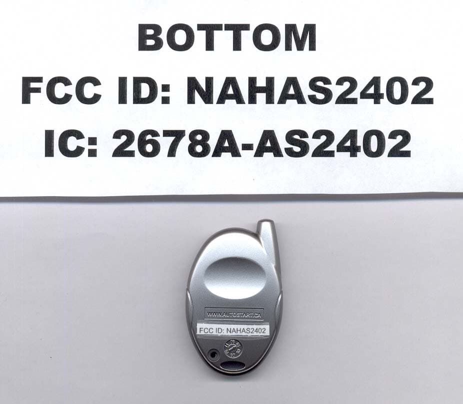
NAHAS2402
Jun 19, 20074 BUTTON OOK REMOTE
Equipment Class
DSC - Part 15 Security/Remote Control Transmitter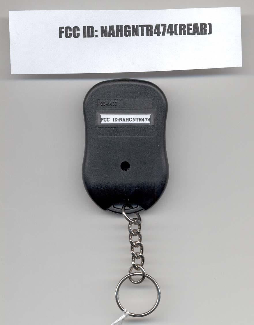
NAHGNTR474
Feb 14, 2007DECURITY TRANSMITTER
Equipment Class
DSC - Part 15 Security/Remote Control Transmitter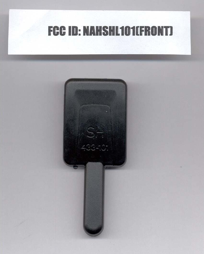
NAHSHL101
Feb 14, 2007SECURITY RECEIVER
Equipment Class
CYY - Communications Receiver used w/Pt 15 Transmitter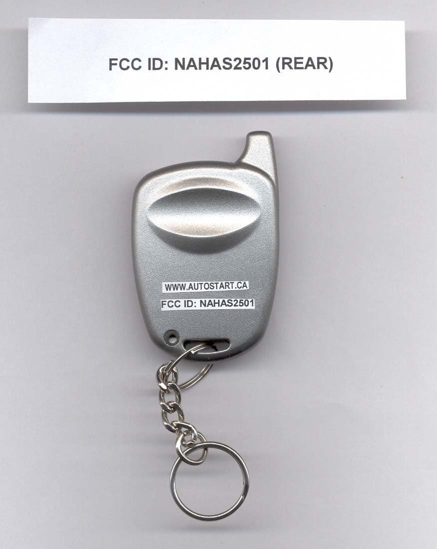
NAHAS2501
Sep 25, 2006REMOTE CONTROL TRANSMITTER
Equipment Class
DSC - Part 15 Security/Remote Control Transmitter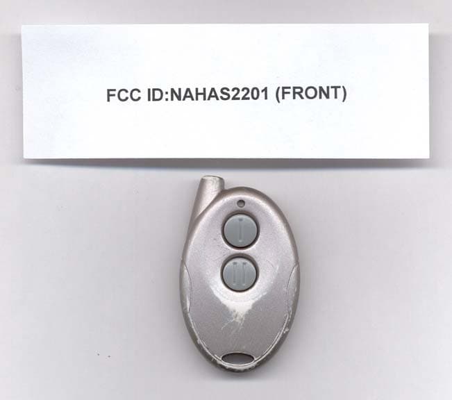
NAHAS2201
Sep 25, 2006TRANSMITTER
Equipment Class
DSC - Part 15 Security/Remote Control Transmitter