NC3BTR2100Security Bracelet Transmitter
Allied Universal Electronic Monitoring US, Inc.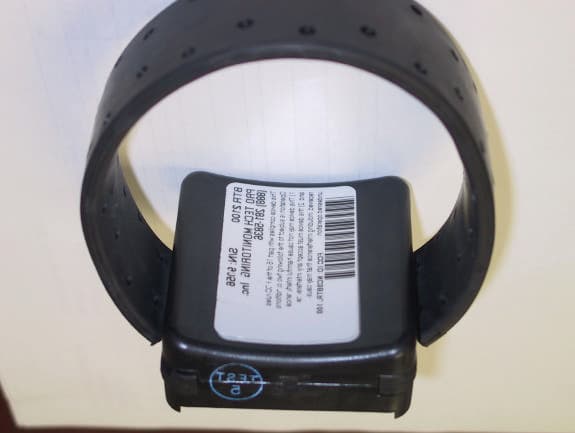
Click to zoom
Application Details
- Equipment Class
- DSC - Part 15 Security/Remote Control Transmitter
- Date of Grant
- Jul 17, 2001
- Application Purpose
- Original Equipment
- Date of Application
- Jul 17, 2001
- Equipment Note
- Security Bracelet Transmitter
- Frequency Range
- 417.00000000 - 419.00000000
- Country
- United States
Documents & Files
Document Text
Text extracted from the exhibit documents filed with the FCC. Open a document above to read the original.
Users Manual
10. Installation and Use 10.1 The Bracelet The offender is fitted with a tamper resistant bracelet transmitter that weighs a little more than 6 ounces. It is attached to a pre-sized strap that comes in various sizes to fit all offenders and is ergonomically designed to be unobtrusive. The bracelet may be worn under socks or hose and reports conditions such as Bracelet Gone (from the vicinity of the Portable Tracking Device), Bracelet Strap (removed or cut) and Battery Status. The bracelet transmitter is a wireless electronic tether to the Portable Tracking Device. Bracelets are assigned to PTD’s through PCE (Pro Tech Client Enrollment). Each bracelet transmits its own unique encrypted RF signal. RF bracelet transmissions from other manufacturers cannot be recognized by the PTD. Once a bracelet is assigned to a PTD, the PTD will only recognize the signal from that bracelet. 10.2 Prior to Installing the Bracelet on an Offender • Verify the bracelet is clean and that the inside of the channels, where the strap ends are inserted on each side of the bracelet, are clean and free of dirt and oil. • Choose a strap that will fit comfortably. A strap size should be chosen so that once installed around an offender’s leg, the bracelet is not too constrictive and it is not too loose. There are four standard strap sizes, small, medium, large and extra large. Special length straps will be supplied by PRO TECH upon request. Requests for non standard strap sizes must be accompanied by a measurement of the offender’s ankle. Ankles should be measured by placing a cloth tape measure around the offender’s ankle at its narrowest point and reading the measurement in inches. • Slide one end of the strap into one of the channels located on the sides of the bracelet. Ensure the strap end has been pushed into the bracelet channel completely. 10.3 Bracelet Installation • Match bracelet serial number on the back of the bracelet case to the number on the bracelet hardware list in PCE 3. Assign that bracelet number to the offender in PCE 3. • Place the strap around the offender’s leg so that the channel openings located on the sides of the bracelet are facing down. This allows any water that may enter the channel to drain out. • Slide the loose end of the strap into the remaining channel at the side of the bracelet. Ensure the strap end has been pushed into the bracelet channel completely. • Align the Tamper Plug with the open holes in the bracelet case. With both hands push the Tamper Plug prongs into the open holes until you get a firm click on both sides. • Note that a bracelet must have both channels connected to activate a PTD. • The bracelet is now activated and transmitting. 10.4 Removing the Bracelet • Cut the Tamper Plug spanner along the scored line, then swing the ends of the Tamper Plug spanner until they are perpendicular to the edge of the bracelet case. Slide the two pieces of the Tamper Plug out of the bracelet case. • Slide one end of the strap out of the bracelet channel. • Clean the bracelet with mild detergent, rinse, dry, and return to inventory. 10.5 FCC NOTICE This device complies with Part 15 of the FCC Rules. Operation is subject to the following two conditions: (1) this device may not cause harmful interference, and (2) this device must accept any interference received, including interference that may cause undesired operation. Any changes or modifications made to this device without the express permission of the manufacturer may void the user's authority to operate this device.
Cover Letter(s)
C:\WINDOWS\TEMP\probonholdemail.doc TIMCO TIMCOTIMCO TIMCO ENGINEERING INC. 849 NW State Road 45 Newberry, Florida 32669 http://www.timcoengr.com 888.472.2424 F 352.472.2030 email: tei@t imcoengr.com 17 July 2001 FCC SUBJECT: PRO TECH MONITORING, INC FCC ID: NC3BTR2100 To Whom It May Concern: The test laboratory confirmed that the EUT was tested in 3 orthogonal planes. Sincerely, Sid Sanders
ID Label/Location Info
BTR 2100 Bracelet Transmitter Label BTR 2100 Bracelet Transmitter with Label
Operational Description
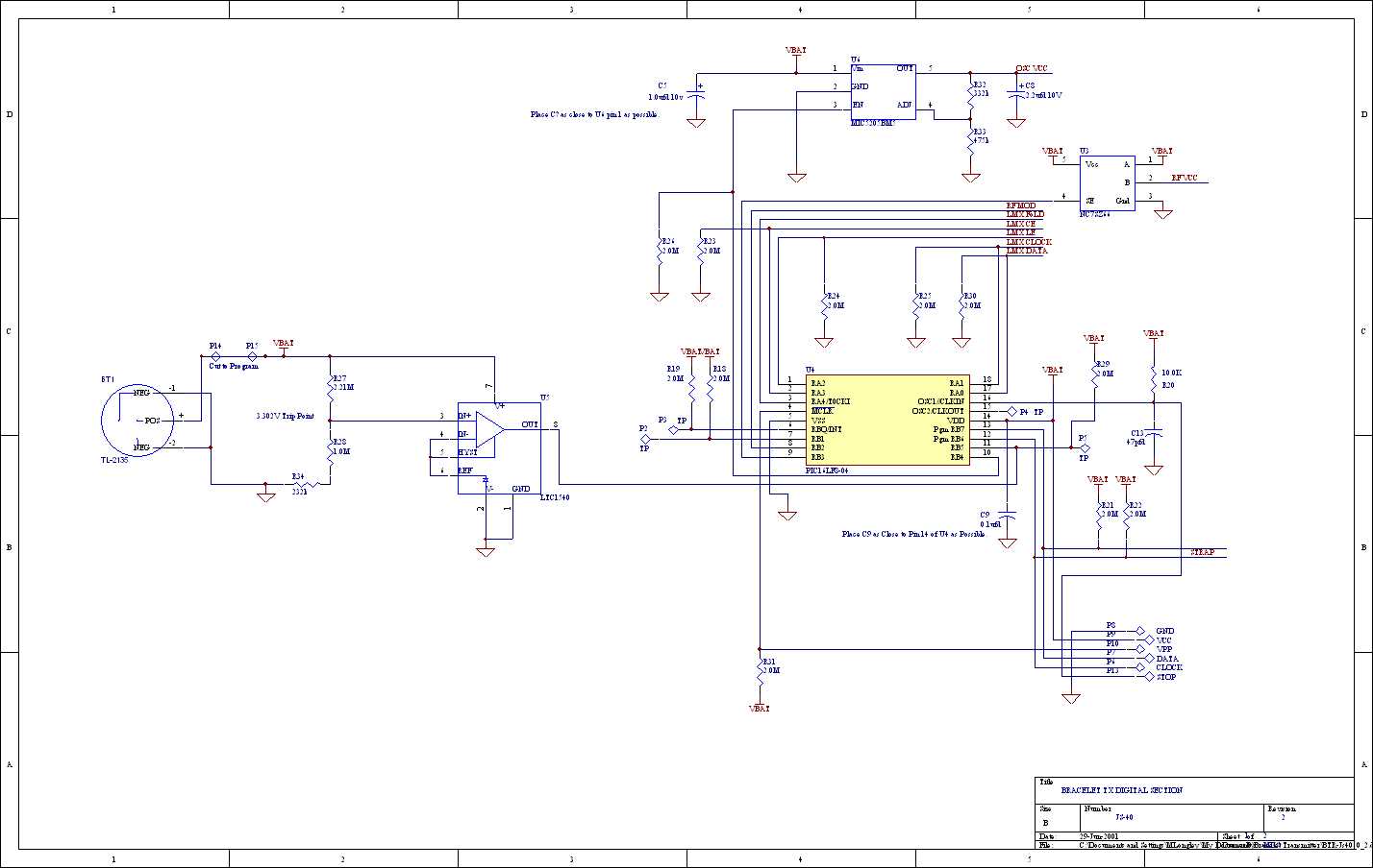
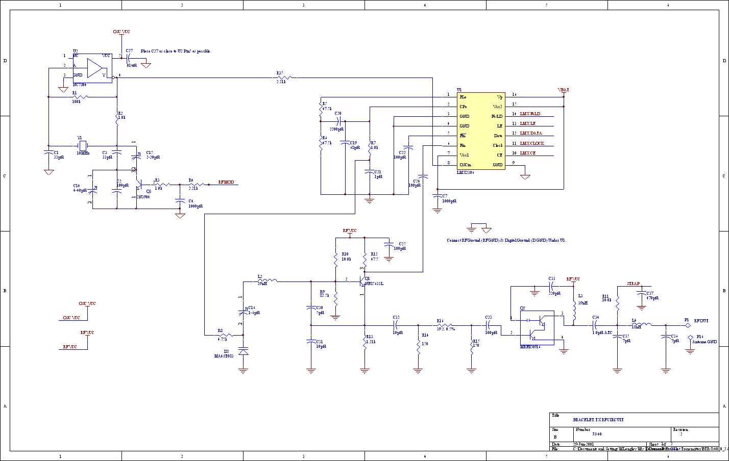
1.Bracelet Transmissions 1.1.Transmission Timing The bracelet packet consists of 7 bytes of data plus one SYNC byte, (as discussed in section 3 below). Each transmission consists of 5 repeats of the bracelet packet and then 10 seconds of quiet. ~10 Sec Idle ~85mSec Transmission ~10 Sec Idle ~10 Sec Idle ~85mSec Transmission ~85mSec Transmission 1.2.Asynchronous Communication All data bytes are transmitted from the bracelet with the addition of asynchronous Start and Stop bits. The data is transmitted at 4800 Baud, with 1 start and 1 stop bit (as shown below). Previous Stop Bit Start Bit LSB Data Byte MSB Stop Bit 208 uSec per bit 1.3.Packet Repeats During each transmission, the packet is repeated 5 times as shown below. Note the addition of a SYNC byte at the end of the 5 SYNC/Packet transmissions. SYNCPacket Data 1 Byte7 Bytes SYNCPacket Data 1 Byte7 Bytes SYNCPacket Data 1 Byte7 Bytes SYNCPacket Data 1 Byte7 Bytes SYNCPacket Data 1 Byte7 Bytes SYNC 1 Byte Bracelet Protocol The bracelet packet consists of the following information (note that the SYNC is not actually part of the packet): Sync Serial Number MSB LSB Packet # MSB LSB CrcHCrcL 8158248 Total Length = 8 Bytes B A T 1 1.4.Sync The SYNC byte is a single byte of data and always contains the value 0xC3 (binary: 1100 0011). The receiver constantly looks for the 7 information bytes between two SYNC bytes. 1.5.BAT Bat is a status bit indicating the health of the bracelet battery. If the Bat bit is a 0, then the battery level is acceptable. A 1 indicates that the hardware is reporting low battery. 1.6.Serial Number Each bracelet is assigned a unique bracelet serial number. This number is permanently burned into the object file (loaded on each bracelet). It is both Manufacturing and Configuration Control’s responsibility to assure that no two bracelets have the same serial number. 1.7.Packet Number The Packet Number is a monotonically increasing number that increments by 1 after each transmission. Thus this can be construed as an approximate 10 Second counter. This Packet Number would theoretically wrap every 5+ years, and since the battery should only last around 3 years, the Packet Number should never wrap. This Packet Number is reset to its initial value under the condition that the bracelet strap is removed (this is an indicator that a bracelet strap tamper occurred). If the bracelet hardware ever indicates that the bracelet strap is removed, then the software should immediately reset this packet number. It should remain reset as long as the bracelet strap tamper is detected. Upon reset, the Packet Number is reset to some fixed value. The value is hardcoded into the software and corresponds to the version of the firmware loaded in the PIC uP. The first version of the firmware, upon reset, will set this Packet Number to 1. The next version of the firmware, upon reset, will set the Packet Number to 3, and so on. All Packet Number reset values will always be odd numbers. 1.8.CRC The CRCH and CRCL (MSB and LSB) represent a 16 bit CRC of the data transmitted. The CRC is calculated on the Battery Status, Serial Number, and Packet Number as shown below: Sync Serial Number MSB LSB Packet # MSB LSB CrcHCrcL 8158248 Total Length = 8 Bytes B A T 1 Calculate CRC16 on this data The CRC algorithm that is used to generate the 16 bit CRC, is shown in the appendix below. Note that the CalculateCRC16(...) function initializes the CRC value to 0xFFFF and that it pushes two bytes of 0’s through after the packet (this is necessary due to the small number of bytes being processed). Analyzer Output
Test Report
Test Report Number 00F516B Product Safety Engineering, Inc 12955 Bellamy Brothers Blvd. Dade City, FL 33525 Tel (352) 588-2209 Fax (352) 588-2544 Page 2 of 12 D I R E C T O R Y - EMISSIONS Page(s) A)Documentation Test report1 - 10 Directory2 Test Regulations3 General Remarks10 Test-setups (Photos)11 - 12 B)Test data Conducted emissions10/150 kHz - 30 MHZ5, 9 Radiated emissions10 kHz - 30 MHZ5, 9 Radiated emissions30 MHZ - 1000 MHZ6, 9 Interference power30 MHZ - 300 MHZ6, 9 Equivalent Radiated emissions1 GHz - 18 GHz7, 9 Antenna Disturbance Voltage30 MHZ - 1,000 MHZ7,9 C)Appendix A Test Equipment Calibration Information A2 Test Data Sheets A3 - A5 D)Appendix B System Under Test DescriptionB2 - B4 E) Appendix C Measurement Protocol C1 - C2 Test Report Number 00F516B Product Safety Engineering, Inc 12955 Bellamy Brothers Blvd. Dade City, FL 33525 Tel (352) 588-2209 Fax (352) 588-2544 Page 3 of 12 EMISSIONS TEST REGULATIONS : The emissions tests were performed according to following regulations: 9 - EN 50081-1 : 1992 9 - EN 50081-2 : 1995 9 - EN 55011 : 1998 / A1:19999 - Group 19 - Group 2 9 - Class A9 - Class B 9 - EN 55013 : 1990 / A12:1994 / A13:1996 9 - EN 55014 : 1993 /A1:19979 - Household appliances and similar 9 - Portable tools 9 - Semiconductor devices 9 - EN 55022 : 19989 - Class A9 - Class B 9 -AS/NZS 3548:19959 - Class A9 - Class B 9 - ICES-0039 - Class A9 - Class B 9 - CNS 134389 - Class A9 - Class B 9 - VCCI : 19999 - Class A9 - Class B # - FCC Part 159 - Class A# - Class B # - Certification 9 - Verification 9 - Declaration of Conformity 9 - FCC Part 18 Test Report Number 00F516B Product Safety Engineering, Inc 12955 Bellamy Brothers Blvd. Dade City, FL 33525 Tel (352) 588-2209 Fax (352) 588-2544 Page 4 of 12 Environmental conditions during testing: LAB OATS Temperature: * _________: ________ Relative Humidity: ** _________: ________ * The ambient temperature during the testing was within the range of (50 - 104 F) unless indicted above. o o ** The humidity levels during the testing was within the range of (10% - 90%) relative humidity unless indicated above. Power supply system: Internal Battery Sign Explanations: 9 - not applicable # - applicable Test Report Number 00F516B Product Safety Engineering, Inc 12955 Bellamy Brothers Blvd. Dade City, FL 33525 Tel (352) 588-2209 Fax (352) 588-2544 Page 5 of 12 Emissions Test Conditions: CONDUCTED EMISSIONS (Interference Voltage) The CONDUCTED EMISSIONS (INTERFERENCE VOLTAGE) measurements were performed at the following test location: # - Test not applicable 9 - Darby Test Site (Open Area Test Site) 9 - Darby Laboratory Test equipment used : Model NumberManufacturerDescriptionSerial Number 9 -8028-50Solar50 Ù LISN829012, 829022 9 -3825/2Solar50 Ù LISN924840 9 -EMC-30Electro-MetricsEMI Receiver191 9 -8566BHewlett-PackardSpectrum Analyzer2421A00526 9 -85650AHewlett-PackardQuasi-Peak Adapter2043A00209 9 -85662AHewlett Packard Analyzer Display2403A07352 9 -8028-50Solar50 Ù LISN903725, 903726 9 -FCC-TLISN-T4Fisher Custom Com.Telecom ISN20072 Emissions Test Conditions: RADIATED EMISSIONS (Magnetic Field) The RADIATED EMISSIONS (MAGNETIC FIELD) measurements were performed at the following test location: 9 - Darby Test Site (Open Area Test Site) 9 - 9 - at a test distance of : 9 - 3 meters 9 - 30 meters # - Test not applicable Test equipment used : Model NumberManufacturerDescriptionSerial Number 9 -96005EatonLog Periodic Antenna1099 9 -BIA-25Electro-MetricsBiconical Antenna4283 9 -8566BHewlett-PackardSpectrum Analyzer2421A00526 9 -85662AHewlett-PackardAnalyzer Display2403A07352 9 -85650AHewlett-PackardQuasi-Peak Adapter2043A00209 9 -ALR-30MElectro-MetricsLoop Antenna824 9 -8447DHewlett PackardPreamplifier2944A06832 9 -EMC-30Electro-MetricsEMI Receiver191 Test Report Number 00F516B Product Safety Engineering, Inc 12955 Bellamy Brothers Blvd. Dade City, FL 33525 Tel (352) 588-2209 Fax (352) 588-2544 Page 6 of 12 Emissions Test Conditions: RADIATED EMISSIONS (Electric Field) The RADIATED EMISSIONS (ELECTRIC FIELD) measurements, in the frequency range of 30 MHZ-1000 MHZ, were tested in a horizontal and vertical polarization at the following test location : 99 - Test not applicable # - Darby Site (Open Area Test Site) 9 - Darby Lab 9 - at a test distance of : # - 3 meters 9 - 10 meters 9 - 30 meters Test equipment used : Model NumberManufacturerDescriptionSerial Number # -96005EatonLog Periodic Antenna1099 # -BIA-25Electro-MetricsBiconical Antenna4283 # -8566BHewlett-PackardSpectrum Analyzer2421A00526 # -85662AHewlett-PackardAnalyzer Display2403A07352 # -85650AHewlett-PackardQuasi-Peak Adapter2043A00209 # -8447DHewlett-PackardPreamplifier (26dB)2944A06832 9 -EMC-30Electro-MetricsEMI Receiver191 9 -8568BHewlett PackardSpectrum Analyzer2407A03213 9 -85650AHewlett PackardQuasi-Peak Adapter2043A00358 9 -85662AHewlett PackardAnalyzer Display2340A05806 9 -LPA30Electro-MetricsLog Periodic2280 9 -BIA 30Electro-Metrics Biconical Antenna3852 Emissions Test Conditions): INTERFERENCE POWER The INTERFERENCE POWER measurements were performed by using the absorbing clamp on the mains and interface cables in the frequency range 30 MHZ - 300 MHZ at the following test location : # - Test not applicable 9 - Darby Lab 9 - 9 - Test equipment used : Model NumberManufacturerDescriptionSerial Number 9 -MDS-21Rhode&SchwarzAbsorbing Clamp8608447020 9 -8566BHewlett-PackardSpectrum Analyzer2421A00526 9 -85662AHewlett-PackardAnalyzer Display2403A07352 9 -85650AHewlett-PackardQuasi-Peak Adapter2043A00209 9 -8447DHewlett-PackardAmplifier (26 dB)2944A06832 Test Report Number 00F516B Product Safety Engineering, Inc 12955 Bellamy Brothers Blvd. Dade City, FL 33525 Tel (352) 588-2209 Fax (352) 588-2544 Page 7 of 12 The EQUIVALENT RADIATED EMISSIONS measurements in the frequency range 1 GHz - 4.2 GHz were performed in a horizontal and vertical polarization at the following test location : # - Darby Test Site (Open Area Test Site) 9 - 9 - 9 - at a test distance of: 9 - 1 meters # - 3…
Text truncated - open the document above for the full version.
Test Setup Photos
Test Report Number 00F516B Product Safety Engineering, Inc 12955 Bellamy Brothers Blvd. Dade City, FL 33525 Tel (352) 588-2209 Fax (352) 588-2544 Page 11 of 12 Test-setup photo(s): Radiated emission 30 MHz - 4180 MHz Test Report Number 00F516B Product Safety Engineering, Inc 12955 Bellamy Brothers Blvd. Dade City, FL 33525 Tel (352) 588-2209 Fax (352) 588-2544 Page 12 of 12 Test-setup photo(s): Radiated emission 30 MHz - 4180 MHz
Contact Information
Applicant
Daniel Williamson(Electronics/RF Engineer Tech)
Test Firm
Product Safety Engineering, Inc.Steven Hoke
Technical Specifications
| # | Rule Parts | Frequency Range | Power Output |
|---|---|---|---|
| 1 | 15.231(e) | 417 MHz - 419 MHz | - |
Other Applications from Allied Universal Electronic Monitoring US, Inc.
NC3-25005AVL
Jan 13, 2026GPS Tracking Device
Equipment Class
DXX - Part 15 Low Power Communication Device TransmitterNC3TRACKER-100
Apr 16, 2024Tracker 100
Equipment Class
DTS - Digital Transmission System
NC3BEACON-100
Feb 18, 2024Beacon-100
Equipment Class
DXX - Part 15 Low Power Communication Device Transmitter
NC3HUB-300
Feb 07, 2024Home comunication unit
Equipment Class
DTS - Digital Transmission System
NC3-24074AVL
Jul 22, 2021GPS Tracking System (RTC)
Equipment Class
DSR - Part 15 Remote Control/Security Device Transceiver