NC3BTR3000BTR 3000 BRACELET
Allied Universal Electronic Monitoring US, Inc.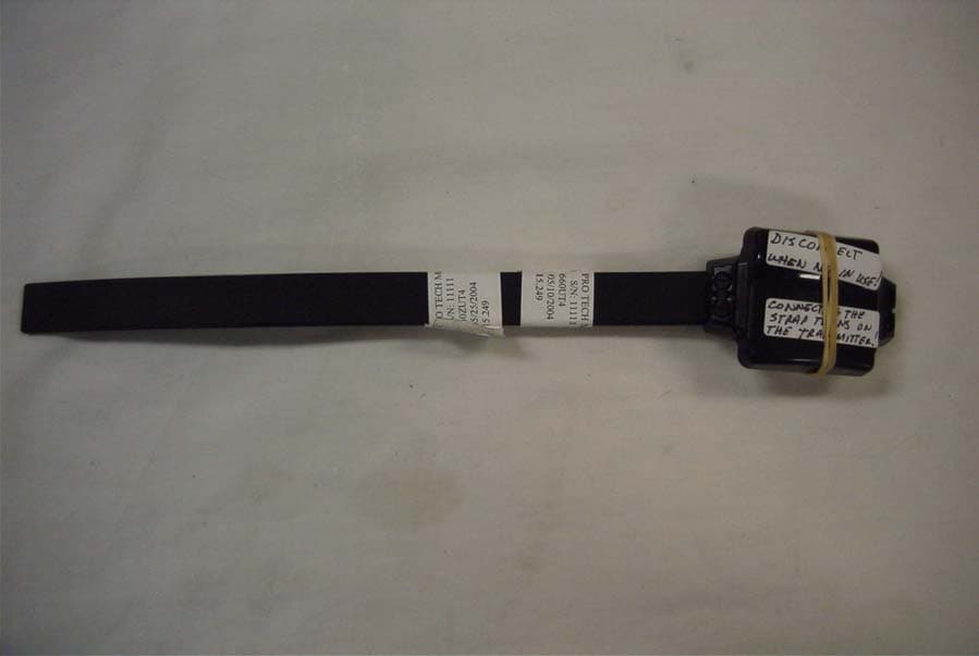
Click to zoom
Application Details
- Equipment Class
- DXX - Part 15 Low Power Communication Device Transmitter
- Date of Grant
- Aug 05, 2004
- Application Purpose
- Original Equipment
- Date of Application
- Aug 05, 2004
- Equipment Note
- BTR 3000 BRACELET
- Frequency Range
- 418.00000000 - 419.00000000
- Country
- United States
Documents & Files
Document Text
Text extracted from the exhibit documents filed with the FCC. Open a document above to read the original.
Users Manual
FCC Certification THIS DEVICE COMPLIES WITH PART 15 OF THE FCC RULES. OPERATION IS SUBJECT TO THE FOLLOWING TWO CONDITIONS: (1) THIS DEVICE MAY NOT CAUSE HARMFUL INTERFERENCE, AND (2) THIS DEVICE MUST ACCEPT ANY INTERFERENCE RECEIVED, INCLUDING INTERFERENCE THAT MAY CAUSE UNDESIRED OPERATION. The authority to operate this equipment may be voided if the user modifies this equipment in any manner without the expressed approval of Pro Tech Monitoring, Inc. FCC IDs: NC3MCS1000, NC3BTR3000 The MTD Charging stand complies with 47 CFR Part 68 of the FCC Rules. Registration Number: US: PTMMD00BMCS1000 Use Standard Jack: USOC RJ11C Ringer Equivalence Number: 0.08 Canadian Certification Notice: This equipment meets the applicable Industry Canada Terminal Equipment Technical Specifications. This is confirmed by the registration number. The abbreviation, IC, before the registration number signifies that registration was performed based on a Declaration of Conformity indicating that Industry Canada technical specifications were met. It does not imply that Industry Canada approved the equipment. Notice: The Ringer Equivalence Number (REN) for this terminal equipment is: 0.08. The REN assigned to each piece of terminal equipment provides an indication of the maximum number of terminals allowed to be connected to a telephone interface. The termination on an interface may consist of any combination of devices subject only to the requirement that the sum of the Ringer Equivalence Number of all devices does not exceed five. Canadian certification Number IC: 4410A-MCS1000.
Operational Description
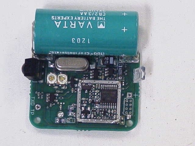
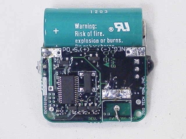
Bracelet Transmitter Circuit Description Prepared by: J. Chris Defant Date: July 23, 2004 The bracelet transmitter schematic consists of two pages, a digital page and an RF page. Digital description The heart of the digital section is a TI MSP430 microprocessor (U1). The TI part was chosen because of its low current drain. The processor has built-in memory where the bracelet transmitter software program resides. The processor program performs the following tasks: 1. Periodically enables CR1 through Q2, Q4, Q5, & Q9. This generates an inferred pulse that is intended to pass along a fiber optic strap. The processor looks for these IR pulses from U6 through Q1. 2. Periodically turns on the regulator for the oscillator (U2), the RF_VCC (Q3). Once the RF section has been powered on, the phase lock loop (PLL) is programmed to a specific frequency and then data is transmitted. 3. Periodically, the processor monitors the battery voltage. The processor is programmed through the J-TAG connector J2. U3 is an exclusive OR gate that can be used to invert the data before it is transmitted. RF Description The reference oscillator (U4) is designed to operate at 10 MHz. The reference oscillator is modulated by the transmitter data by pulling the reference oscillator off frequency ± 8 KHz. This is accomplished by switching out capacitors C13 and C14 with Q6. The signal (10 MHz) is fed to the programmable PLL U5. The VCO circuit consists of D1 and Q7. The FM output signal from the PLL is fed through an attenuator (R24, R25, & R26) and is amplified by Q8. L4 and C34 impedance match the built-in antenna to the 50ohm output of Q8.
Schematics
123456 A B C D 654321 D C B A ScaleSheet SizeFCSM No.DWG No.Rev 1 of 2 B6300-0255 Pro Tech Monitoring, Inc. 2549 Success Drive Odessa, Florida 33556-3401 Phone (727) 484-3100, Fax (727) 484-3111 New Bracelet Transmitter (Micro-Processor) [5/29/2003] GND GND +VBAT C5 0.1uF JTAG PROGRAMMING HEADER GND +VBAT RST* TCK TMS TDI TDO R1 100K TEST 1 P1.0 (TACLK/ADC10CLK) 21 P1.1 (TA0) 22 P1.2 (TA1) 23 P1.3 (TA2) 24 P1.4 (SMCLK/TCK) 25 P1.5 (TA0/TMS) 26 P1.6 (TA1/TDI) 27 P1.7 (TA2/TDO/TDI) 28 P2.0 (ACLK/A0) 8 P2.1 (INCLK/A1) 9 P2.2 (TA0/A2) 10 P2.3 (TA1/A3/VREF-) 19 P2.4 (TA2/A4/VREF+) 20 P2.5 (Rosc) 3 (STE0/A5) P3.0 11 (SIMO0) P3.1 12 (SOMI0) P3.2 13 (UCLK0) P3.3 14 (UTXD0) P3.4 15 (URXD0) P3.5 16 (A6) P3.6 17 (A7) P3.7 18 RST/NMI 7 VSS 4 VCC 2 XIN 6 XOUT 5 U1 MSP430F1232 1 3 5 2 4 6 78 J2 CON2X4 +VBAT C4 0.1uF GND TEST PLL-LD PLL-CE PLL-LE PLL-CLK PLL-DATA TEST INPUTS R5 475K +VBAT IR-RX-EN* CR1 LTE-302 R8 1.5K 1 2 J3 CON2 R6 475K +VBAT +VBAT STRAP OPTICAL RECEIVER STRAP OPTICAL TRANSMITTER GND Q1 IRLML6402 RXD TEST1 TEST2 1 1 4 4 Y1 38.4 KHz GND TXD + C1 47uF, 6V GND +VBAT GND GND +VBAT R3 332K R4 475K + C3 2.2uF, 10V GND GND +VBAT RF-VCC OSC-VCC Q3 IRLML6402 TX-DATA VCC 5 OUT 4 IN 1 IN 2 GND 3 U3 NC7S86M5X +VBAT TX-DATA-INV IN 1 OUT 5 ADJ 4 EN 3 GND 2 U2 MIC5205BM5 3V LITHIUM BATTERY GND GND R7 5.1M, DNL RF-EN* OSC-EN C7 0.1uF R11 0R0, DNL + - B1 VARTA-CR2/3AA C35 470pF GND OUT 1 Vs 2 GND 3 U6 TSOP32138 1 TP1 TXD R9 750 R10 360 +VBAT Q2 IRLML6402 Q9 IRLML2502 Q5 IRLML2502 Q4 IRLML2502 GNDGNDGND R2 1.5K GND IR-TX-EN* IR-TX-SEL2 IR-TX-SEL1 IR-TX-SEL0 R30 475K GND C6 0.1uF GND + C33 0.1F, 5 VDC GND 123456 A B C D 654321 D C B A ScaleSheet SizeFCSM No.DWG No.Rev 2 of 2 B6300-0255 Pro Tech Monitoring, Inc. 2549 Success Drive Odessa, Florida 33556 Phone (727) 484-3100, Fax (727) 484-3111 New Bracelet Transmitter (RF Section) [5/29/2003] R27 100K 1 1 2 2 Y2 10MHz 1 2 C14 3-30pF 1 2 C11 2-20pF GND GND OSC-VCC R12 1K R14 1K R13 2.2K GND R17 47.5K R16 47.5K R18 1K R19 4.75K D1 SMU1235-079 L1 47nH R21 82.5K R20 10K R22 47.5 R23 1.21K E B C Q7 NE85619 GND R24 68 R26 68 R25 100 GND GND GNDGNDGND L2 39nH L3 18nH GNDGND GND GND RF-VCC RF-VCC GND PLL-LD PLL-LE PLL-DATA PLL-CLK PLL-CE GND GND GND 1 2 34 5NC A GND VCC Y U4 NC7SU04M5 TX-DATA GND 1 2 4 3 Q8 MBC13916 +VBAT R15 2.21K ANTENNA-RF 1 2 J4 Ant. RF GND PLACE C8 AS CLOSE TO U4 PIN 5 AS POSSIBLE. C8 0.1uF C9 39pF C12 18pF C13 27pF C10 1000pF C32 7pF C31 7pF C30 1pF C29 220pF GND C28 100pF C27 10pF GND GND GND RF-VCC C22 100pF C16 2200pF C17 68pF C18 100pF C15 1pF C19 0.01uF C26 100pF C24 5pF C25 10pF +VBAT C20 0.01uF GND C21 0.1uF GND GND GND GND GND C23 10pF C34 4.3pF GND Antenna to be a metal strip loop from one end of PCB to the other, encircling battery. Antenna ground to be returned to the ground of C34 using min 30 Mil. track. Leave this here for testing B B C C E E Q6 MMBT3904 OUTGND J5 Antenna FLo 1 CPo 2 GND 3 GND 4 Vp 16 Vcc2 15 Fo/LD 14 LE 13 Data 12 Clock 11 CE 10 GND 9 Fin 5 Fin 6 Vcc1 7 OSCin 8 U5 LMX2306 L4 120nH
Test Report
TIMCO ENGINEERING INC. 849 NW State Road 45 Newberry, Florida 32669 http://www.timcoengr.com 888.472.2424 F 352.472.2030 email: [email protected] APPLICANT: PRO TECH MONITORING, INC FCC ID: NC3BTR3000 REPORT #: P\PTECH\660ZUT4\660ZUT4TestReport.doc COVER SHEET Test Report Product Name: MONITORING BRACELET FCC ID: NC3BTR3000 Applicant: PRO TECH MONITORING, INC 2549 SUCCESS DRIVE ODESSA FL 33556 Date Receipt: MAY 25, 2004 Date Tested: JULY 16, 2004 TIMCO ENGINEERING INC. 849 NW State Road 45 Newberry, Florida 32669 http://www.timcoengr.com 888.472.2424 F 352.472.2030 email: [email protected] APPLICANT: PRO TECH MONITORING, INC FCC ID: NC3BTR3000 REPORT #: P\PTECH\660ZUT4\660ZUT4TestReport.doc TABLE OF CONTENTS APPLICANT: PRO TECH MONITORING, INC FCC ID: NC3BTR3000 TABLE OF CONTENTS TEST REPORT CONTAINING: PAGE 1...........TEST EQUIPMENT LIST PAGE 2...........TEST PROCEDURE PAGE 3...........RADIATION INTERFERENCE TEST DATA PAGE 4...........OCCUPIED BANDWIDTH PAGE 5...........OCCUPIED BANDWIDTH PLOT EXHIBIT INCLUDED: BLOCK DIAGRAM SCHEMATIC USERS MANUAL LABEL SAMPLE LABEL LOCATION EXTERNAL PHOTOGRAPHS INTERNAL PHOTOGRAPHS OPERATIONAL DESCRIPTION TEST SET UP PHOTOGRPAHS TIMCO ENGINEERING INC. 849 NW State Road 45 Newberry, Florida 32669 http://www.timcoengr.com 888.472.2424 F 352.472.2030 email: [email protected] APPLICANT: PRO TECH MONITORING, INC FCC ID: NC3BTR3000 REPORT #: P\PTECH\660ZUT4\660ZUT4TestReport.doc Page 1 of 5 EMC Equipment List Device Manufacturer Model Serial Number Cal/Char Date Due Date 3/10-Meter OATS TEI N/A N/A Listed 3/27/04 3/26/07 3-Meter OATS TEI N/A N/A Listed 1/13/03 1/13/06 Biconnical Antenna Eaton 94455-1 1057 CAL 3/18/03 3/18/05 Biconnical Antenna Eaton 94455-1 1096 CAL 10/1/01 10/1/03 Biconnical Antenna Electro- Metrics BIA-25 1171 CAL 4/26/01 4/26/03 Blue Tower Quasi-Peak Adapter HP 85650A 2811A01279 CAL 4/15/03 4/15/05 Blue Tower RF Preselector HP 85685A 2620A00294 out for Cal Blue Tower Spectrum Analyzer HP 8568B 2928A04729 2848A18049 CAL 4/15/03 4/15/05 LISN Electro- Metrics ANS-25/2 2604 CAL 10/9/01 10/9/03 LISN Electro- Metrics EM-7820 2682 CAL 3/12/03 3/12/05 Log- Periodic Antenna Eaton 96005 1243 CAL 5/8/03 5/8/05 TIMCO ENGINEERING INC. 849 NW State Road 45 Newberry, Florida 32669 http://www.timcoengr.com 888.472.2424 F 352.472.2030 email: [email protected] APPLICANT: PRO TECH MONITORING, INC FCC ID: NC3BTR3000 REPORT #: P\PTECH\660ZUT4\660ZUT4TestReport.doc Page 2 of 5 TEST PROCEDURE GENERAL: This report shall NOT be reproduced except in full without the written approval of TIMCO ENGINEERING, INC. The UUT was transmitting a test signal during the testing. RADIATION INTERFERENCE: The test procedure used was ANSI STANDARD C63.4-1992 using a HEWLETT PACKARD spectrum analyzer with a pre-selector. The analyzer was calibrated in dB above a microvolt at the output of the antenna. The resolution bandwidth was 100KHz and the video bandwidth was 300KHz up to 1.0GHz and 1.0MHz with a video BW of 3.0MHz above 1.0GHz. The ambient temperature of the UUT was 74.3oF with a humidity of 69%. FORMULA OF CONVERSION FACTORS: The Field Strength at 3m was established by adding the meter reading of the spectrum analyzer (which is set to read in units of dBuV) to the antenna correction factor supplied by the antenna manufacturer. The antenna correction factors are stated in terms of dB. The gain of the Preselector was accounted for in the Spectrum Analyzer Meter Reading. Example: Freq (MHz) METER READING + ACF = FS 33 20 dBuV + 10.36 dB = 30.36 dBuV/m @ 3m ANSI STANDARD C63.4-1992 10.1.7 MEASUREMENT PROCEDURES: The UUT was placed on a table 80 cm high and with dimensions of 1m by 1.5m. The UUT was placed in the center of the table (1.5m side). The table used for radiated measurements is capable of continuous rotation. When an emission was found, the table was rotated to produce the maximum signal strength. At this point, the antenna was raised and lowered from 1m to 4m. The antenna was placed in both the horizontal and vertical planes. TIMCO ENGINEERING INC. 849 NW State Road 45 Newberry, Florida 32669 http://www.timcoengr.com 888.472.2424 F 352.472.2030 email: [email protected] APPLICANT: PRO TECH MONITORING, INC FCC ID: NC3BTR3000 REPORT #: P\PTECH\660ZUT4\660ZUT4TestReport.doc Page 3 of 5 APPLICANT: PRO TECH MONITORING, INC FCC ID: NC3BTR3000 NAME OF TEST: RADIATION INTERFERENCE RULES PART NUMBER: 15.249, 15.209 REQUIREMENTS: Field Strength of Fundamental – 94 dBuV/m FIELD STRENGTH S15.209 of Harmonics 30 - 88 MHz 40 dBuV/m @3M 88 - 216 MHz 43.5 216 - 960 MHz 46 ABOVE 960 MHz 54dBuV/m EMISSIONS RADIATED OUTSIDE OF THE SPECIFIED FREQUENCY BANDS, EXCEPT FOR HARMONICS, SHALL BE ATTENUATED BY AT LEAST 50 dB BELOW THE LEVEL OF THE FUNDAMENTAL OR TO THE GENERAL RADIATED EMISSION LIMITS IN 15.209, WHICHEVER IS THE LESSER ATTENUATION. TEST RESULTS: This unit DOES meet the FCC requirements. TEST DATA: Tuned Frequency MHz Emission Frequency MHz Meter Reading dBuV Ant. Polarity Coax Loss dB Correction Factor dB Field Strength dBuV/m Margin dB 418.0 418.00 48.8 H 1.22 16.64 66.66 27.34 418.0 418.00 54.5 V 1.22 16.28 72.00 22.00 418.0 835.90 4.6 V 1.97 21.98 28.55 25.45 *All other emissions were more than 20 dB below the limit* TEST PROCEDURE: ANSI STANDARD C63.4-1992 using a Hewlett Packard Model 8566B spectrum analyzer, a Hewlett Packard Model 85685A Pre-selector, a Hewlett Packard Model 85650A Quasi-Peak adapter, and an appropriate antenna. The bandwidth of spectrum analyzer was 100 kHz with an appropriate sweep speed. When an emission was found, the table was rotated to produce the maximum signal strength. The antenna was placed in both the horizontal and vertical planes and the worse case emissions were reported. The spectrum was searched to at least the tenth (10) harmonic of the fundamental. PERFORMED BY: NAM NGUYEN DATE: JUNE 22, 2004 TIMCO ENGINEERING INC. 849 NW State Road 45 Newberry, Florida 32669 http://www.timcoengr.com 888.472.2424 F 352.472.2030 email: [email protected]…
Text truncated - open the document above for the full version.
Test Report
849 NW STATE ROAD 45 NEWBERRY, FL 32669 USA PH: 888.472.2424 OR 352.472.5500 FAX: 352.472.2030 EMAIL: [email protected] HTTP://WWW.TIMCOENGR.COM FCC PART 15.231(e) TEST REPORT LOW POWER UNLICENSED TRANSMITTER Applicant PRO TECH MONITORING, INC Address 2549 SUCCESS DRIVE ODESSA FL 33556 USA FCC ID NC3BTR3000 Product Description MONITORING BRACELET Test Results Pass Fail THE ATTACHED REPORT SHALL NOT BE REPRODUCED EXCEPT IN FULL WITHOUT THE WRITTEN APPROVAL OF TIMCO ENGINEERING, INC. Certificate # 0955-01 APPLICANT: PROTECH MONITORING, INC FCC ID: NC3BTR3000 REPORT: P\PTECH\949UT8\949UT8TestReport.doc Page 1 of 12 APPLICANT: PROTECH MONITORING, INC FCC ID: NC3BTR3000 REPORT: P\PTECH\949UT8\949UT8TestReport.doc Page 2 of 12 TABLE OF CONTENTS GENERAL REMARKS ....................................................................................................3 REPORT SUMMARY ......................................................................................................4 TEST ENVIRONMENT....................................................................................................4 TEST SETUP .................................................................................................................4 DUT SPECIFICATION ....................................................................................................5 TEST EQUIPMENT LIST ................................................................................................6 TEST PROCEDURES .....................................................................................................7 RADIATION INTERFERENCE .........................................................................................8 CALCULATION OF DUTY CYCLE .................................................................................10 OCCUPIED BANDWIDTH.............................................................................................11 POWER LINE CONDUCTED INTERFERENCE ..............................................................12 GENERAL REMARKS The attached report shall not be reproduced except in full without the written permission of Timco Engineering Inc. Summary The device under test does: fulfill the general approval requirements as identified in this test report not fulfill the general approval requirements as identified in this test report Attestations This equipment has been tested in accordance with the standards identified in this test report. To the best of my knowledge and belief, these tests were performed using the measurement procedures described in this report. All instrumentation and accessories used to test products for compliance to the indicated standards are calibrated regularly in accordance with ISO 17025 requirements. Certificate # 0955-01 I attest that the necessary measurements were made, under my supervision, at: Timco Engineering Inc. 849 NW State Road 45 Newberry, Fl 32669 Authorized Signatory Name: Mario de Aranzeta C.E.T. Compliance Engineer/ Lab. Supervisor APPLICANT: PROTECH MONITORING, INC FCC ID: NC3BTR3000 REPORT: P\PTECH\949UT8\949UT8TestReport.doc Page 3 of 12 APPLICANT: PROTECH MONITORING, INC FCC ID: NC3BTR3000 REPORT: P\PTECH\949UT8\949UT8TestReport.doc Page 4 of 12 REPORT SUMMARY Disclaimer The test results only relate to the item tested. Applicable Rule(s) FCC Pt 15.231, Pt 15.209, Pt 15.207, ANSI C63.4: 2003 TEST ENVIRONMENT Test Facility The test sites are located at 849 NW State Road 45 Newberry, FL 32669 USA. Test Condition: Temperature: 26ºC Relative humidity: 50% TEST SETUP Test Exercise (e.g software description, test signal, etc.): The DUT was placed in continuous transmit mode of operation. Deviation from the standard(s) No deviation from the standard(s) Modification to the DUT: No modification was made to the DUT. Supporting Peripheral Equipment Not applicable. The device is a stand-alone remote control radio. APPLICANT: PROTECH MONITORING, INC FCC ID: NC3BTR3000 REPORT: P\PTECH\949UT8\949UT8TestReport.doc Page 5 of 12 DUT SPECIFICATION Applicant PRO TECH MONITORING, INC Description MONITORING BRACELET FCC ID NC3BTR3000 Frequency Range 418-419 MHz 110–120Vac/50– 60Hz DC Power DUT Power Source Battery Operated Exclusively Test Item Prototype Pre-Production Production Type of Equipment Fixed Mobile Portable APPLICANT: PROTECH MONITORING, INC FCC ID: NC3BTR3000 REPORT: P\PTECH\949UT8\949UT8TestReport.doc Page 6 of 12 TEST EQUIPMENT LIST Device Manufacturer Model Serial Number Cal/Char Date Due Date 3/10-Meter OATS TEI N/A N/A Listed 3/27/04 3/26/07 3-Meter OATS TEI N/A N/A Listed 1/13/03 1/13/06 Biconnical Antenna Eaton 94455-1 1057 CAL 3/18/03 3/18/05 Biconnical Antenna Eaton 94455-1 1096 CAL 10/1/01 10/1/03 Biconnical Antenna Electro- Metrics BIA-25 1171 CAL 4/26/01 4/26/03 Blue Tower Quasi-Peak Adapter HP 85650A 2811A01279 CAL 4/15/03 4/15/05 Blue Tower RF Preselector HP 85685A 2620A00294 out for Cal Blue Tower Spectrum Analyzer HP 8568B 2928A04729 2848A18049 CAL 4/15/03 4/15/05 LISN Electro- Metrics ANS-25/2 2604 CAL 10/9/01 10/9/03 LISN Electro- Metrics EM-7820 2682 CAL 3/12/03 3/12/05 Log-Periodic Antenna Eaton 96005 1243 CAL 5/8/03 5/8/05 APPLICANT: PROTECH MONITORING, INC FCC ID: NC3BTR3000 REPORT: P\PTECH\949UT8\949UT8TestReport.doc Page 7 of 12 TEST PROCEDURES Power line conducted Emissions: The test procedure used was ANSI C63.4-2003. Spurious Emissions: The test procedure used was ANSI C63.4-2003 using a spectrum analyzer with a preselector. The bandwidth of the spectrum analyzer was 100 kHz with an appropriate sweep speed. The analyzer was calibrated in dB above a microvolt at the output of the antenna. The resolution bandwidth was 100 kHz and the video bandwidth was always greater than the RBW. Occupied Bandwidth: A small sample of the transmitter output was fed into the spectrum analyzer and a was generated. The vertical scale is set to 10 dB per division. Formula Of Conversion Factors: The field strength at 3m was established by adding the meter reading of the s…
Text truncated - open the document above for the full version.
Contact Information
Applicant
Daniel Williamson(Electronics/RF Engineer Tech)
Test Firm
Timco Engineering, Inc.S Sanders
Technical Specifications
| # | Rule Parts | Frequency Range | Power Output |
|---|---|---|---|
| 1 | 15C | 418 MHz - 419 MHz | - |
Other Applications from Allied Universal Electronic Monitoring US, Inc.
NC3-25005AVL
Jan 13, 2026GPS Tracking Device
Equipment Class
DXX - Part 15 Low Power Communication Device TransmitterNC3TRACKER-100
Apr 16, 2024Tracker 100
Equipment Class
DTS - Digital Transmission System
NC3BEACON-100
Feb 18, 2024Beacon-100
Equipment Class
DXX - Part 15 Low Power Communication Device Transmitter
NC3HUB-300
Feb 07, 2024Home comunication unit
Equipment Class
DTS - Digital Transmission System
NC3-24074AVL
Jul 22, 2021GPS Tracking System (RTC)
Equipment Class
DSR - Part 15 Remote Control/Security Device Transceiver