NC3WMTD3418ANKLE WRIST WORN GPS TRACKING DEVICE
Allied Universal Electronic Monitoring US, Inc.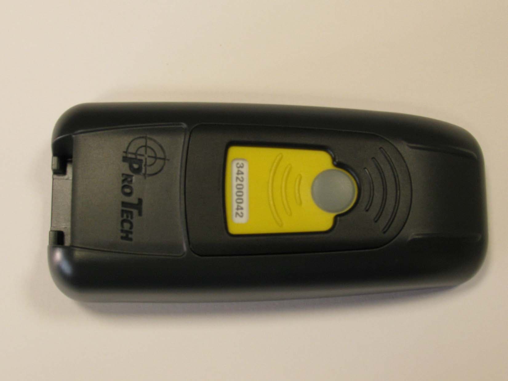
Click to zoom
Application Details
- Equipment Class
- DSR - Part 15 Remote Control/Security Device Transceiver
- Date of Grant
- Mar 02, 2010
- Application Purpose
- Original Equipment
- Date of Application
- Mar 01, 2010
- Equipment Note
- ANKLE WRIST WORN GPS TRACKING DEVICE
- Frequency Range
- 418.00000000 - 418.00000000
- Country
- United States
Documents & Files
Document Text
Text extracted from the exhibit documents filed with the FCC. Open a document above to read the original.
Users Manual
1 SMART ® ACTIVE TRACKING System Overview Pro Tech’s Wearable Miniature Tracking Device (WMTD) utilizes GPS satellites to establish an offender’s location by utilizing the cellular network to transmit the data. Alert Button Bracket Serial Number Charging Port WMTD Communication and GPS Point Storage • The standard WMTD call-in interval is once every hour while in compliance • The WMTD will call Pro Tech as soon as a violation occurs, if a Contact is selected • If the WMTD is not able to make a call because of poor cellular coverage, it will continue trying to call in until it is successful • The WMTD collects a GPS point every minute. If a Geographic Rule is in violation, the WMTD will collect a GPS point every 15 seconds. 2 WMTD Indicator LEDs There are three LEDs on the top of the WMTD, identified as Power, GPS, and Zone. The three LEDs work separately and provide the offender with information. It is possible for any LED to be flashing Green or Red and it is acceptable for the LEDs to be off. The WMTD will vibrate to provide an indication that the offender must look at the LEDs. The LEDs function as follows: PWR Zone GPS PWR LED • This LED indicates the condition of the WMTD battery. o LED off and WMTD deactivated: Acts as a battery indicator during the activation process when the Alert Button is pressed o LED off and WMTD activated: The WMTD is in power save mode o LED blinking Green: The WMTD is either activated or in the process of being activated. The battery does not need to be charged o LED blinking Red: The WMTD is activated and the battery requires charging • When the WMTD is connected to the charger, this LED will be solid (not flashing) Green or Red. o LED Red: The WMTD is not fully charged and should not be disconnected from the charger o LED Green: The WMTD battery has been completely charged and the charger may be disconnected GPS LED • LED off: In normal condition • LED flashing Green: It will flash in unison with the flashing “ZONE” LED during activation • LED flashing Red: Indicates a Motion No GPS warning or violation ZONE LED • LED off: In normal conditions • LED flashing Green: It will flash in unison with the flashing“GPS” LED during activation • LED flashing Red: Indicates an Inclusion or an Exclusion Zone warning or violation 3 Rule Definitions Hardware Rules WMTD Battery • The battery is getting low and the device needs to be charged. The device must be charged for a minimum of two hours daily (the hours do not have to be consecutive). When the battery needs to be charged, the device will vibrate three times consecutively and then once every ten minutes until connected to the charger. During this time, the Power LED will blink Red. Motion No GPS • Occurs when the WMTD has accumulated 10 minutes of motion in a 60 minute period without receiving a signal from the GPS satellites. The device will vibrate three times consecutively and once every ten minutes until the violation has cleared by acquiring GPS. During this time, the GPS LED will blink Red. WMTD Strap • The strap has been compromised or removed from the WMTD. There will not be any notifications to the offender that this has occurred, unless the officer selects the Notify Offender with Vibrate option on this rule. WMTD Alert Button Pressed • When pressed, this button sends an alert to the contact. If the offender presses and holds the button for one second, a single vibration will occur. This will also send out a notification to the contact(s) specified on the rule. WMTD Unable to Connect • It has been over 2 ½ hours since the WMTD has contacted Pro Tech. This is normally due to poor cellular coverage in the area. The offender is not notified of the Unable to Connect. Once the WMTD is able to use the cellular network to call in, it will report the violation and download all tracking data. WMTD Tamper • The WMTD has been compromised in some form. There will not be any notification to the offender that this has occurred, unless the officer selects the Notify Offender with Vibrate option on this rule. 4 Rule Definitions Cont. Geographic Rules Zone Rules- The offender has violated a Zone set up by the user. The device will vibrate three times consecutively and once every ten minutes while still in violation, if the Notify With Vibrate feature is checked. The Zone LED will blink in Red. • Inclusion Zone o Geographic areas like home, work, or school where the offender is confined during an officer defined schedule • Exclusion Zone o Geographic areas used to define off-limits areas to the offender 5 Activating the WMTD Equipment 1. Press and hold the Alert Button on the front of the WMTD for 3 seconds. If the “PWR” LED is Green then proceed with activation. If the “PWR” LED is Red or does not light up at all, then the WMTD will need to be charged prior to activating. 2. Push tamper plugs into the back of the brackets of the WMTD. Be sure to insert the left side first. 3. Place the pin tray on a flat surface, such as a desk, and push one end of the strap into the pin tray until it is level with the “lip” of the pin tray. Make sure that there is no gap between the end of the strap and the edge of the pin tray. 4. Insert strap with attached pin tray into one side of the WMTD until it snaps in place. 5. Place the WMTD on the offender’s leg, just below the ankle bone. 6. Wrap the strap around the offender’s leg and measure to the line shown at right so that it allows approximately ¼ inch of space between the offender’s leg and the strap to ensure comfort. 6 Activating the WMTD Equipment Cont. 7. Using the strap cutters, cut the strap according to the measurement taken in step six. Wipe off any fiber optic cable residue left on the strap after cutting has been completed. 8. Place remaining pin tray on a flat surface and insert measured end of the underneath side (the bottom) of the strap into the pin tray. 9. Place the WMTD on the offender’s leg just below the ankle bone and insert the strap with attached pin tray into t…
Text truncated - open the document above for the full version.
Cover Letter(s)
February 22,2010 Federal Communications Commission Authorization and Evaluation Division Confidentiality Request regarding application for certification of FCC ID: NC3WMTD34I 8. Pursuant to Sections 0.457 and 0.459 of the Commission's Rules, we hereby request confidential treatment of information accompanying this application as outlined below: Exhibit Type Schematic Diagrams Bill of Materials (BOM) Block Diagrams File Name wMTD34t8 wMTD34l8 wMTD34t8 Schematic.pdf BOM.pdf Block Diagram.pdf Pro Tech Monitoring develops equipment to monitor criminal offenders. Offenders are given operational instructions from their probation officer who is trained by Pro Tech personnel. In addition, the above materials contain trade secrets and proprietary information not customarily released to the public. The public disclosure of these materials may be harmful to the applicant and provide unjustified benefits to its competitors. The applicant understands that pursuant to Section0.457 of the Rules, disclosure of this application and all accompanying documentation will not be made before the date of the Grant for this application. Sincerely, PRO TECH MONITORING, lNC.. 1838 GUNN HIGHWAY'ODESSA, FL 33556 PHONE 81 3.749.5454 . 888.67.SMART' FAX 81 3.749.5474 www.ptm.com
Cover Letter(s)
oTEcn Declaration of conformance This device does not contain a manually operated transmitter. The automatically activated transmitter ceases transmission within 5 seconds after activation. This is a security or safety application. This device transmits at regular predetermined intervals. The total duration of transmissions does not exceed more than two seconds per hour. The total transmission time does not exceed two seconds per hour. Transmitter Timing 418MHz X+15sec A 1.8 msec +l- 0.2 msec ooo X sec 1q \n---L, 1 .8 msec +l- 0.2 msec X+30sec kF+ 1.8 msec +l- 0.2 Chris Defant VP Engineering Pro Tech Monitoring PRO TECH MONITORING, lNC.. 1838 GUNN HIGHWAY'ODESSA, FL 33556 PHONE 813.749.5454 .888.67.SMART . FAX 813.749.5474 www.ptm.com
Operational Description
WMTD Operational Description Introduction The Wearable Miniature Tracking Device (WMTD) was designed to help probation and parole officers monitor offenders. It is attached to the offender using a rubber-fltb strap. It collects positional information and compares this data to rules that have been establish.d Uy probation or parole officer. These rules geographically define where an offender is allowed or. ,rot allowed to go. The WMTD also includes hardware to determine if the WMTD has been tampered with or removed. An ISM transceiver operating at 433MHz is included so that the WMTb may communicate with a base unit placed in the offender's home to verify home curfew. System Overview The WMTD utilizes GPS to establish an offender's location. Position al data(points) are stored every minute while the offender is not in violation of any rule and every I 5 seconds whenever he or she is in violation. The cellular network (GPRS) is uied to transmit the databack to servers at Pro Tech's data center located in Odessa. FL. Alert Bracket- Serial Number Charging Port PRO TECH MONITORING, INC. . 1838 GUITIT.I HIGHWAY. ODESSA, FL 33556 Button PHONE 81 3.749.5454 . 88B.G7.SMART . FAX 81 9.749.5474 www.ptm.com The WMTD is comprised of the following subsystems: 1. GPS Antenna and Receiver 2. C'StrrttCPRS cellular modem 3. Microprocessor running application software and memory 4. Battery and battery charging circuit 5. Tamper detection circuit including I/R emitter and receiver for monitoring a fiber-optic cable in the strap. 6. Alert pushbutton for offender acknowledgements. Both the GPS receiver and GSM modem are off-the-shelf modules. 4il*o{4 2
RF Exposure Info
Applicant: Pro Tech Monitoring, Inc. FCC ID: NC3WMTD3418 FCC KDB Inquiry Track No. 727730 Model: WMTD3418 Device Type: Dual-Band PCS/Cellular GPRS Ankle-worn Tracking Device 2010 Celltech Labs Inc. This document is not to be reproduced in whole or in part without the prior written permission of Celltech Labs Inc. Page 1 of 1 RFx Exhibit Serial No. 021010NC3-T1006-S24G RFx Exhibit Issue Date March 02, 2010 RFx Exhibit Revision No. Rev. 1.1 (2nd Release) Test Lab Certificate No. 2470.01 RF EXPOSURE EXHIBIT (FCC KDB INQUIRY TRACKING NUMBER 727730) Pro Tech Monitoring Inc. Model: WMTD3418 Dual-Band GPRS Ankle-worn Tracking Device FCC ID: NC3WMTD3418 Per FCC KDB Inquiry Tracking Number 727730 This device has been excluded from SAR testing based on source-based time-averaged conducted output power is less than 60/f per manufacturer-specified 1/10 minutes maximum transmission duration in addition to the GPRS Class 10 transmission duty factor of 2/8 slots utilized. This document serves as the RF exposure exhibit in the FCC Form 731 application in lieu of a SAR report and has been reviewed and accepted by the FCC prior to submittal to the TCB. Operational Description The WMTD is an ankle-worn offender tracking device utilizing GPS to establish an offender’s location. Positional (data) points are stored every minute while the offender is not in violation of any rule and every 15 seconds whenever the offender is in violation. The GPRS transmitter is utilized to transmit the data back to servers at the Pro Tech Monitoring data center. RF Exposure Conditions The WMTD ankle-worn tracking device is intended for operation in the General Population / Uncontrolled RF exposure environment. GPRS Antenna-to-Ankle Separation Distance ~ 0.420 inches (per manufacturer) Transmission Mode The WMTD tracking system utilizes an internal GPRS Class 10 transmitter (2/8 uplink slots). Duty Cycle The WMTD tracking system collects GPS position information once a minute. This data is sent back to the Pro Tech Monitoring datacenter no more than every 10 minutes. It typically takes approximately 1 minute to send this information. RF Output Power GPRS Mode - Cellular 850 Band Average Conducted Output Power = 32.0 dBm / 1.6 Watts Source-Based Time-Averaged Duty Cycle - 2/8 uplink slots = 25% Source-Based Time-Averaged Duty Cycle - 1/10 minutes = 10% Source-Based Time-Averaged Output Power = 16 dBm (40 mW) 60/f (GHz) mW = 70.7 mW Source-based time-averaged conducted output power = < 60/f GPRS Mode - PCS 1900 Band Average Conducted Output Power = 30.0 dBm / 1 Watt Source-Based Time-Averaged Duty Cycle - 2/8 uplink slots = 25% Source-Based Time-Averaged Duty Cycle - 1/10 minutes = 10% Source-Based Time-Averaged Output Power = 14 dBm (25 mW) 60/f (GHz) mW = 31.4 mW Source-based time-averaged conducted output power = < 60/f Simultaneous Transmission 418 MHz Beacon Transmitter Antenna-to-Antenna Spacing = 0.140” Manuf. Rated Cond. Power = +12 dBm Tx-on time = 1.8ms / Tx-off time = 14.8s Manufacturer Duty Cycle Spec. = 0.012% 60/f (GHz) mW = 143.5 mW Source-based time-averaged conducted output power = < 60/f RF Exposure Exhibit Revision No.s Revision 1.1 - Corrected GPRS duty factor and source-based time-averaged output power levels - March 02, 2010 Revision 1.0 - Initial Release - March 01, 2010
Test Report
FCC PART 15.231 TEST REPORT LOW POWER UNLICENSED TRANSMITTER Applicant PRO TECH MONITORING, INC Address 2549 SUCCESS DRIVE ODESSA FL 33556 USA FCC ID NC3WMTD3418 Product Description 418 MHZ ANKLE TRACKING MONITOR Date Sample Received 2/5/2010 Date Tested 2/22/2010 Tested By Richard Block Approved By Mario de Aranzeta Timco Report No. 322AUT10TestReport.pdf Test Results Pass Fail THE ATTACHED REPORT SHALL NOT BE REPRODUCED EXCEPT IN FULL WITHOUT THE WRITTEN APPROVAL OF TIMCO ENGINEERING, INC. 849 NW STATE ROAD 45 NEWBERRY, FL 32669 USA PH: 888.472.2424 OR 352.472.5500 FAX: 352.472.2030 EMAIL: [email protected] HTTP: //WWW.TIMCOENGR.COM Certificate # 0955-01 APPLICANT: PRO TECH MONITORING, INC FCC ID: NC3WMTD3418 REPORT: P\PTECH\322AUT10\322AUT10TestReport.doc Page 3 of 14 TABLE OF CONTENTS GENERAL REMARKS .................................................................................................... 4 REPORT SUMMARY ...................................................................................................... 5 TEST ENVIRONMENT .................................................................................................... 5 TEST SETUP ................................................................................................................. 5 DUT SPECIFICATION .................................................................................................... 6 MANUFACTURE DECLARATION OF COMPLIANCE WITH PART 15.231(E) ...................... 7 TEST EQUIPMENT LIST ................................................................................................ 8 TEST PROCEDURES ..................................................................................................... 9 RADIATION INTERFERENCE ....................................................................................... 10 CALCULATION OF DUTY CYCLE ................................................................................. 12 OCCUPIED BANDWIDTH ............................................................................................. 13 POWER LINE CONDUCTED INTERFERENCE .............................................................. 14 APPLICANT: PRO TECH MONITORING, INC FCC ID: NC3WMTD3418 REPORT: P\PTECH\322AUT10\322AUT10TestReport.doc Page 4 of 14 GENERAL REMARKS The attached report shall not be reproduced except in full without the written permission of Timco Engineering Inc. Summary The device under test does: fulfill the general approval requirements as identified in this test report not fulfill the general approval requirements as identified in this test report Attestations This equipment has been tested in accordance with the standards identified in this test report. To the best of my knowledge and belief, these tests were performed using the measurement procedures described in this report. All instrumentation and accessories used to test products for compliance to the indicated standards are calibrated regularly in accordance with ISO 17025 requirements. Certificate # 0955-01 I attest that the necessary measurements were made, under my supervision, at: Timco Engineering Inc. 849 NW State Road 45 Newberry, Fl 32669 Authorized Signatory Name: Mario de Aranzeta C.E.T. Compliance Engineer/ Lab. Supervisor Date: February 23, 2010 APPLICANT: PRO TECH MONITORING, INC FCC ID: NC3WMTD3418 REPORT: P\PTECH\322AUT10\322AUT10TestReport.doc Page 5 of 14 REPORT SUMMARY Disclaimer The test results only relate to the item tested. Applicable Rule(s) FCC Pt 15.231, Pt 15.209, Pt 15.207, ANSI C63.4: 2003 Related Report(s) or Approval(s) Receiver The receiver portion of this system has been tested and meets all of the FCC requirements per FCC rules Part 15.109. A report was issued and a copy of this report is available upon request. TEST ENVIRONMENT Test Facility The test sites are located at 849 NW State Road 45 Newberry, FL 32669 USA. Test Condition: Temperature: 26ºC Relative humidity: 50% TEST SETUP Test Exercise (e.g software description, test signal, etc.): The DUT was placed in continuous transmit mode of operation. Deviation from the standard(s) No deviation from the standard(s) Modification to the DUT: No modification was made to the DUT. Supporting Peripheral Equipment Not applicable. The device is a stand-alone remote control radio. APPLICANT: PRO TECH MONITORING, INC FCC ID: NC3WMTD3418 REPORT: P\PTECH\322AUT10\322AUT10TestReport.doc Page 6 of 14 DUT SPECIFICATION Applicant PRO TECH MONITORING, INC Description 418 MHZ ANKLE TRACKING MONITOR FCC ID NC3WMTD3418 Model Number WMTD3418 Frequency Range 418 MHz DUT Power Source 110–120Vac/50– 60Hz DC Power Battery Operated Exclusively Test Item Prototype Pre-Production Production Type of Equipment Fixed Mobile Portable APPLICANT: PRO TECH MONITORING, INC FCC ID: NC3WMTD3418 REPORT: P\PTECH\322AUT10\322AUT10TestReport.doc Page 7 of 14 MANUFACTURE DECLARATION OF COMPLIANCE WITH PART 15.231(E) 15.231(e) “In addition, devices operated under the provisions of this paragraph shall be provided with a means for automatically limiting operation so that the duration of each transmission shall not be greater than one second and the silent period between transmissions shall be at least 30 times the duration of the transmission but in no case less than 10 seconds.” The DUT transmits 1.784 ms every 15 seconds, and therefore is compliant with the standard listed above. APPLICANT: PRO TECH MONITORING, INC FCC ID: NC3WMTD3418 REPORT: P\PTECH\322AUT10\322AUT10TestReport.doc Page 8 of 14 TEST EQUIPMENT LIST Device Manufacturer Model Serial Number Cal/Char Date Due Date 3/10-Meter OATS TEI N/A N/A Listed 3/20/07 3/19/10 3-Meter OATS TEI N/A N/A Listed 1/11/09 1/10/12 3-Meter Semi- Anechoic Chamber Panashield N/A N/A Listed 5/11/07 5/10/10 Analyzer Silver Tower Quasi-Peak Adapter HP 85650A 3303A01844 CAL 10/30/08 10/30/10 Analyzer Silver Tower RF Preselector HP 85685A 2620A00294 CAL 3/6/09 3/6/11 Analyzer Silver Tower Spectrum Analyzer HP 8566B Opt 462 3552A22064 3638…
Text truncated - open the document above for the full version.
Contact Information
Applicant
Daniel Williamson(Electronics/RF Engineer Tech)
Test Firm
Timco Engineering, Inc.Bruno Clavier
Technical Specifications
| # | Rule Parts | Frequency Range | Power Output |
|---|---|---|---|
| 1 | 15.231 | 418 MHz - 418 MHz | - |
Other Applications from Allied Universal Electronic Monitoring US, Inc.
NC3-25005AVL
Jan 13, 2026GPS Tracking Device
Equipment Class
DXX - Part 15 Low Power Communication Device TransmitterNC3TRACKER-100
Apr 16, 2024Tracker 100
Equipment Class
DTS - Digital Transmission System
NC3BEACON-100
Feb 18, 2024Beacon-100
Equipment Class
DXX - Part 15 Low Power Communication Device Transmitter
NC3HUB-300
Feb 07, 2024Home comunication unit
Equipment Class
DTS - Digital Transmission System
NC3-24074AVL
Jul 22, 2021GPS Tracking System (RTC)
Equipment Class
DSR - Part 15 Remote Control/Security Device Transceiver