NC3XT06418Criminal Offenders GPS Tracker
Allied Universal Electronic Monitoring US, Inc.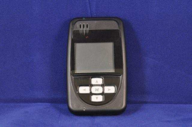
Click to zoom
Application Details
- Equipment Class
- DSR - Part 15 Remote Control/Security Device Transceiver
- Date of Grant
- Mar 02, 2011
- Application Purpose
- Original Equipment
- Date of Application
- Mar 01, 2011
- Equipment Note
- Criminal Offenders GPS Tracker
- Frequency Range
- 418.00000000 - 418.00000000
- Country
- United States
Documents & Files
Document Text
Text extracted from the exhibit documents filed with the FCC. Open a document above to read the original.
Users Manual
Pro Tech Monitoring Inc. Issue Date: 2/14/2011 Please check online for the most up to date version. 0 Pro Tech Monitoring Inc. Issue Date: 2/14/2011 Please check online for the most up to date version. 1 Table of Contents Overview........................................................................................................................................ - 2 - Operating Features .......................................................................................................................... - 3 – Bracelet Details ............................................................................................................................... - 4 - SMART Base Details ......................................................................................................................... - 5 - Enrollment ....................................................................................................................................... -6- Enroll a Contact ............................................................................................................................ - 7- Contact Information Page ........................................................................................................... ..- 10 - Enroll an Offender ....................................................................................................................... - 11 - Supervision Level .......................................................................................................................... -12- Map Offender’s Address ................................................................................................................ - 15- Offender General Information Page ................................................................................................. - 16- Create Schedule for Home Inclusion Zone .......................................................................................... - 17- Create Exclusion Zone ..................................................................................................................... - 21- Activating the XT ........................................................................................................................... - 25 - Deactivating Hardware .................................................................................................................... - 32 - Removing the Bracelet ................................................................................................................... - 36 – Appendix ....................................................................................................................................... - 38 - Accessing the Officer Menu ............................................................................................................. - 40 – Accessing the Offender Menu ........................................................................................................... - 41 - Pro Tech Monitoring Inc. Issue Date: 2/14/2011 Please check online for the most up to date version. 2 Overview Pro Tech’s SMART ® XT utilizes GPS satellites to establish an offender’s location and uses cellular networks to transmit the location data to Pro Tech. The SMART ® XT transmits all GPS data every hour, unless there is a violation. If a violation has occurred, the GPS data is transmitted immediately. The SMART ® XT consists of four components: The Ankle Bracelet, the XT, the SMART ® Base and SMART ® View and the carrying pouch accessory. Note: Depending on the customer’s needs, the SMART ® Base may not be utilized. Steps for activating without the SMART ® Base are contained within this manual. Pro Tech Monitoring Inc. Issue Date: 2/14/2011 Please check online for the most up to date version. 3 Operating Features Sim Card: The XT has a SIM card, which is similar to the data transmitter/receiver found in most cellular phones. The XT uses the SIM card to transmit and download the GPS points it has generated to Pro Tech’s servers. The call-in intervals vary, depending on whether or not the XT is in active mode or passive mode. The differences between the two modes are explained below: Battery Life: The device should be given a full charge (4.2 volts) to supply a full day of battery life. It takes approximately 4 hours to acquire a full charge. The daily life of the battery is dependent upon the call-in interval of the device, how often it goes to rest, and how many violations are created. The battery must be charged each day in order to continue to track your offender’s locations. Range: When undocked, the XT has a transmittal range of 75-100 feet. When docked, the transmittal range will increase to 125- 150 feet. Vibrate feature: Officers can choose to enable the vibration mode to alert the offender of any violations and/or messages. The vibration will continue until the offender has acknowledged the violation and/or message. Storing GPS Points: The XT collects and stores a GPS point every minute. If a geographic rule is in violation, the XT will collect and store a GPS point every 15 seconds. The GPS point history will then be transmitted to Pro Tech every hour or every six hours while in the SMART Base – when in compliance. If the GPS point is in violation, the XT will contact Pro Tech immediately. Call-in intervals: The XT calls Pro Tech every hour while out of the SMART Base, or every 6 hours while in the SMART Base - when in compliance. If in violation, the XT will contact Pro Tech immediately. At Rest: If the XT is left in the same place for 10 consecutive minutes without any motion, the XT will go to “Rest” and collect a point at the top of every hour instead of every minute. This feature is designed to conserve the battery life. While the XT is at rest, it will still be communicating the bracelet and ensuring that the offender is in range. Automatic Redial: If the XT is unable to communicate with Pro Tech because of poor cellular coverage, …
Text truncated - open the document above for the full version.
Users Manual
Pro Tech Monitoring Inc. Issue Date: 2/14/2011 Please check online for the most up to date version. 17 Create Schedule for Home Inclusion Zone 1. Click on the In Charger Rule (see below). Pro Tech Monitoring Inc. Issue Date: 2/14/2011 Please check online for the most up to date version. 18 Create Schedule for Home Inclusion Zone, Cont. 2. Move your mouse cursor over the Rule Functions dropdown menu and left click Edit. Pro Tech Monitoring Inc. Issue Date: 2/14/2011 Please check online for the most up to date version. 19 Create Schedule for Home Inclusion Zone, Cont. 3. You will be redirected to the Edit Rule page. Scroll down to the Permanent Rule Schedule. Pro Tech Monitoring Inc. Issue Date: 2/14/2011 Please check online for the most up to date version. 20 Create Schedule for Home Inclusion Zone, Cont. 4. Each block represents a 30 minute increment of time. Left-click and drag the cursor along the blocks during the times that the offender is required to be home. As you move the cursor, the blocks will turn blue. The white blocks that remain equal the times that the offender is allowed to be out of the home (see below). 5. Click the Save button. Pro Tech Monitoring Inc. Issue Date: 2/14/2011 Please check online for the most up to date version. 21 Create Exclusion Zone You can create an Exclusion Rule to ensure that the offender is not entering areas which are forbidden – such as schools, playgrounds, and victims’ residences. 1. Move your cursor over the Rule Functions menu (see below). 2. Left click Add Zone. Pro Tech Monitoring Inc. Issue Date: 2/14/2011 Please check online for the most up to date version. 22 Create Exclusion Zone, Cont. 3. Choose a Zone Shape. 4. Choose Exclusion as the Zone Type. 5. Click the Continue button. Pro Tech Monitoring Inc. Issue Date: 2/14/2011 Please check online for the most up to date version. 23 Create Exclusion Zone Cont. 6. Enter the Rule Name (school, playground, etc.). 7. Enter the address information and the zone size. The default is 600 ft. 8. Select Yes or No if you want to notify the offender upon violation. 9. If you selected Yes to notify the offender upon violation, type the message you want displayed on the XT screen in the Offender Message field. 10. Choose the appropriate Contact from the Notification Contact drop down list. The contact’s default notification method will appear selected. 11. Click the Add button. 12. Click the Map button. Pro Tech Monitoring Inc. Issue Date: 2/14/2011 Please check online for the most up to date version. 24 Create Exclusion Zone, Cont. 13. Ensure that the address and zone size is correct. 14. If you want to resize or move the zone, click the Move/Resize button. 15. If you move or resize the zone, click the Finish Move/Resize button. 16. Click the Submit button. Pro Tech Monitoring Inc. Issue Date: 2/14/2011 Please check online for the most up to date version. 25 STEP 1: Plug A/C adapter into a wall outlet. Activating the SMART ® XT with SMART ® Base Connecting the SMART ® Base STEP 2: Plug A/C adapter into the back of the SMART ® Base where 12VDC is located. The green power light will light up on the front of the unit. STEP 3: If offender has a phone line: A: Remove phone line from telephone and plug into the back of the SMART ® Base marked PHONE. B: Take extra phone cord and plug one end back into the telephone and the other end into the SMART ® Base marked LINE. Pro Tech Monitoring Inc. Issue Date: 2/14/2011 Please check online for the most up to date version. 26 Connecting the SMART ® Base, cont. STEP 4: If activating at office: A: Remove phone line from facsimile machine. B: Plug facsimile phone line into the SMART ® Base. SMART ® Base - Violation Status Lights: Power: The SMART ® Base has lost power. Line: The phone line has been disconnected. Curfew: The XT is not in the SMART ® Base when the schedule is in effect. Message: The offender needs to contact the officer. Activating the SMART ® XT with SMART ® Base Pro Tech Monitoring Inc. Issue Date: 2/14/2011 Please check online for the most up to date version. 27 Step 1: Place the XT into the SMART ® Base. Ensure the SMART ® Base is connected to the A/C power cord. Note : Ensure the hardware has been assigned and saved to the offender’s profile. Step 2: Press the Activate button (center button). Step 3: Press the Scroll button (bottom button) to select “Using Wireless” to activate using the cellular network. If activating via the SMART ® Base, select which prefix (if any) the SMART ® Base must dial to complete a call. Refer to Connecting the SMART Base STEP 3 for additional instructions. Activating the SMART ® XT Activating the SMART ® XT with SMART ® Base Pro Tech Monitoring Inc. Issue Date: 2/14/2011 Please check online for the most up to date version. 28 Activating the SMART ® XT, cont. Step 4: Press the Activation button to begin dialing. The XT will begin to contact the Pro Tech Data Center. “Contacting Data Center” will be displayed on the screen. Once contact is complete, the XT will begin to search for the bracelet. “Searching for Bracelet will be displayed on the screen. Note : Both sides of the strap must be connected to the bracelet and it, the bracelet, must be in range of the XT. Once the XT recognizes the bracelet, it will display “Waiting for GPS.” Remove the XT from the SMART ® Base. Step 5: Walk the XT outside, holding it upright in an area with a clear view of the sky. Once GPS has been acquired, the XT will beep and display the message “Activation Successful.” Click on the Activation button to acknowledge. After the Activation button has been clicked, the XT will display the offender’s name, date and time. Activating the SMART ® XT with SMART ® Base Pro Tech Monitoring Inc. Issue Date: 2/14/2011 Please check online for the most up to date version. 29 Activating the SMART ® XT without SMART ® Base Activating the SMART ® XT Step 1: Plug A/C adapter into a wall outlet. Activating the SMART ® XT without SMART ® Base cont. Step 3: Press th…
Text truncated - open the document above for the full version.
Users Manual
Pro Tech Monitoring Inc. Issue Date: 2/14/2011 Please check online for the most up to date version. 31 Activating the SMART ® XT without SMART ® Base cont. Activating the SMART ® XT cont. Step 7: Click on the Activation button to acknowledge. After the Activation button has been clicked, the XT will display the offender’s name, date and time. Pro Tech Monitoring Inc. Issue Date: 2/14/2011 Please check online for the most up to date version. 32 Deactivating Hardware 1. Move your mouse cursor over the Hardware Functions dropdown menu and left click Deactivate. Pro Tech Monitoring Inc. Issue Date: 2/14/2011 Please check online for the most up to date version. 33 Deactivating Hardware, Cont. 2. Click the checkbox next to the XT, Bracelet, and SMART Base. (see below). 3. Click on the drop-down menu and select a reason for deactivation. This is required. Pro Tech Monitoring Inc. Issue Date: 2/14/2011 Please check online for the most up to date version. 34 Deactivating Hardware, Cont. 4. Click the Save button. A popup will generate with a warning that the deactivation is immediate. 5. Click OK. Pro Tech Monitoring Inc. Issue Date: 2/14/2011 Please check online for the most up to date version. 35 Deactivating Hardware, Cont. 6. You will be returned to the Offender Information page, where the hardware will be pending deactivation. The device is now required to call Pro Tech and transmit its final data. The hardware will only be unassigned once this final call has occurred. Pro Tech Monitoring Inc. Issue Date: 2/14/2011 Please check online for the most up to date version. 36 Removing the Bracelet Removing the Bracelet Step 1: Cut the strap by using the strap cutters and remove the Bracelet from the offender’s leg. Step 2: Using a Pro Tech flathead screwdriver, push on the tamper plugs to break them. Step 3: Use the screwdriver to remove the tamper plugs from the brackets. Pro Tech Monitoring Inc. Issue Date: 2/14/2011 Please check online for the most up to date version. 37 Removing the Bracelet cont. Removing the Bracelet Cont. Step 4: While keeping the latch depressed, pull the strap with the attached pin trays out of each bracket. Discard the tamper plugs and straps. Note: Do NOT reuse the tamper plugs. Note: Do NOT remove tamper plugs from the brackets of the Bracelet unless there is a strap with an attached pin tray inside the bracket. Pro Tech Monitoring Inc. Issue Date: 2/14/2011 Please check online for the most up to date version. 38 Appendix Rule Definitions Bracelet Battery: • The Bracelet battery is getting low; the bracelet must be replaced within seven days. Bracelet Gone: • Occurs when the offender is out of range of the tracking device. Therefore the location of the offender is unknown. • If the “Notify Offender” box is checked in PCE, the offender will receive the automatic message “Bracelet Gone- Please move closer.” • The range of the bracelet to the XT. o 75 to 100 ft (clear line of site) away from XT while out of Base Unit; OR o 125 to 150 ft (clear line of site) away from XT while in the Base Unit • Pro Tech adds a 5 minute buffer period to all Bracelet Gone violations. This is not a Grace Period. During this time, the offender is not notified of the Bracelet Gone. Only after five minutes have passed will the Bracelet Gone Rule go into violation. If you add a Grace, it will apply after five minute buffer has passed. For example, if a one minute grace is set, the bracelet will have to be out of range for 6 minutes before notifications are sent out. Bracelet Strap: • The bracelet strap has been compromised or removed from the bracelet. Base Unit A/C Power: • The SMART ® Base has lost A/C power and is running on the battery back-up. Base Unit Battery: • The SMART ® Base has been running on the back-up battery and is about to lose power. With a full charge (24 hours) the back-up battery will last 24 hours. While running on the back-up battery, the SMART ® Base will not charge the XT. If the XT is in the SMART ® Base, and the SMART ® Base can call in, the XT will still be able to successfully download its information. Base Unit Phone Line Disconnect: • The phone line has been removed from the SMART ® Base. You will not get this alert until the phone line has been re-connected, because the SMART ® Base requires a phone line to report violations. Base Unit Tamper: • The SMART ® Base has been compromised in some form. Base Unit Unable to Connect: • The SMART ® Base has not called Pro Tech in 6.5 hours. Pro Tech Monitoring Inc. Issue Date: 2/14/2011 Please check online for the most up to date version. 39 Phone Number Caller ID: • Signals the offender may have moved the SMART ® Base to a new phone line or home. • The number cannot be “private” or “unlisted.” Home Curfew/In Charger: • The XT is NOT in the assigned SMART Base when the In Charger schedule is in effect. Motion No GPS: • Occurs when the XT has accumulated 10 minutes of motion in a 60-minute period without receiving a signal from the GPS satellites. • If the “Notify Offender” box is checked in PCE/SMART ® View the offender is sent the automatic message “GPS Warning-Go Outside”. The offender has 10 minutes (grace period) from this point to clear the Motion No GPS warning message before it becomes a violation and notifications are sent out. • When GPS is reacquired, the offender is notified with the automatic message “GPS Warning Cleared”. • If the offender does NOT regain GPS at the end of the 10 minute grace period, a Motion No GPS violation is created. Zone: • The offender has violated a Zone set up by the supervising officer or agency. This could be an Exclusion (out-of-bound) Zone or an Inclusion (in-bound) Zone. XT Battery: • The XT battery is low and needs to be placed in the SMART ® Base. The offender receives the automatic message “Battery Low-Place in Base Unit”. XT Tamper: • The XT has been compromised and/or tampered with. Active XT Unable to Connect: • It has been over 2.5 hours since the XT has called in. The offen…
Text truncated - open the document above for the full version.
Block Diagram
Janu a Enfor docu m Pro Te Rega r Rob H Direct Enfora 2 ary 21, 2011 a Inc. here b ments held o ech Monitori rds, Holden tor Complian a, Inc. 251 Renner Pkwy by authorises n file for the ing, Inc. XT (0 nce Engineeri y, Richardson, T s RFI Global Enfora mod u 06318 and 06 ng Texas 75080 | 9 Letter of Services Ltd ule GSM0408 418) device F 972.633.4400 T f Authoriza d on behalf 8‐40 with FCC FCC IDs NC3XT Tel | 972.633.44 ation of Pro Tech C ID MIVGSM XT06318; NC3 444 Fax | www. h Monitoring M0408, to sup 3XT06418. .enfora.com g, Inc. to us pport the app se Enfora Inc plication of th c. e
Cover Letter(s)
Tecu January 3,zALl Telecom m unication Certification Body RFI Global Services Ltd. Pavilion A Ashwood Park Basingstoke Hampshire RG23 8BG United Kingdom To whom it may concern This is to certify that Pro Tech Monitoring authorizes RFl Gtobatto act on our behalf for the application of the NC3XT06418 to RFI Global Services Ltd. Telecommunication certification Body. We certify that we are not subject to a denial of Federal benefits, that include FCC benefits, pursuant to Section 5301 of the Anti-Drug Abuse Act of 1988, 21 U.S.C S 862 because of a conviction for possession or distribution of a controlled substance. See 47 CFR 1.2002(b) for the definition of a "party" for these purposes. Yours sincerely, Chris Defant Vice President of Engineering PRO TECH MONITORING, lNC. . 1838 GUNN HIGHWAY. ODESSA, FL 33556 PHON E 81 3.749.5 454 . 888.67.SMART . FAX 8 1 3.7 49.547 4 www.ptm.com
Cover Letter(s)
January 3,2011 Federal Communications Commission Authorization and Evaluation Division Confidentiality Request regarding application for certification of FCC ID: NC3XT06418 Pursuant to Sections A.457 and 0.459 of the Commission's Rules, we hereby request confidential treatment of information accompanying this application as outlined below: Exhibit Type Schematic Diagrams Bill of' Materials (BOM) File Name XT 41 8 Touchpad Board XT 418 Schematic.pdf XT 41 8 Touchpad Board XT 418 BOM.pdf Schematic.pdf BOM.pdf Pro Tech Monitoring develops equiprnent to monitor criminal offenders. Offenders are given operational instructions from their probation officer who is trained by Pro Tech personnel. In addition, the above materials contain trade secrets and proprietary information not customarily released to the public. The public disclosure of these materials may be harmful to the applicant and provide unjustified benefits to its competitors. The applicant understands that pursuant to SrctionA.457 of the Rules, disclosure of this application and all accompanying documentation will not be made befbre the date of the Grant for this application. Sincerely, PRO TECH MONITORING, lNC.. 1838 GUNN HIGHWAY. ODESSA, FL 33556 PHONE 813.749.5454 . 888.67.SMART . FAX 813.749.5474 www.ptm.com
ID Label/Location Info
MODEL:06418 FCC ID: NC3XT06418
Operational Description
XT0641 8 CI peratisn al Descnp ti on !ntroduction llrc X'f' (nrotlel trutnber X f06i+181 luas designed to he'lp probation auci parolc ol'liecrr., lniln{tiir' oflendcrs. "l'he olhncicr carries the X'f nnd ar brracelet transniitter that is attached to iris anli{,-' trrovidcs an elcctronic ieti:er. 'I-he X"f ccllects GPS positianal informatiorr and corrrpliler-; ti;i.; iJata to rules tlrat have hecn establishccl b1,' a probation or parole off-rcer. I'hcsc rulcs r:cograplrically'delinc n'llere an of li:r'ldcr ii; ailolre:d or not aliou,ed to go. 'i-ire X'l lrlso jnc:liri!rs hardr.l'are to detennine i1-it has breen lantpcrecl with. $ystem Overview !'ht'X-l'trtilizes GPS tr.r e:itablish anof-fender's location. P*sitional data(points) arri s1{ilrii t."o,r..r'} ininute r,vhilc thc olTend*r is not in r,,ioiil.lion of anv rule arrd e vLrr\' 15 secorrcis rvlrcrrLrvii lrc ci" :;itc is in l'ioiation. 'l'h,.r c:,-'iiular netr,l'orh (GPRS)is used to transnlit the data back to s,..rrrr':; ril llril 'l'eclr's clata c'cntcr iocated in Oclcssa" FL. L('l) tr{csponsc }Juttons PRO TECH MONITORING, INC. PHONE 813.749.5454 .1838 GUNN HIGHWAY. ODESSA, FL 33556 . 888.67.SMART . FAX 813.749.5474 www.ptm.com 'I'he X'f is comXlrised of the fbllowing subsystems: I . ti PS fteceiver" ii,irri Antenna 2. {iSN'l\GPRS ccliulal lnoden"r 3. 'l-ranscciver ancl anlcnna operating at rll8MHz 4. Microprocessor running application software and ntemory 5. f]attcrv and traticr3' charging circuit 6. I'anrper detection circuit. 7 . ltesponse pushhuttctis fbr oflbnder acknowledgemeruts. Ilotlr tlic GIIS receiver i:ntl GSM moclern arc ofJ'-the-shell'modules.
Operational Description
CC1101 SWRS061E Page 1 of 97 Low-Power Sub-1 GHz RF Transceiver (Enhanced CC1100 ) Applications Ultra low-power wireless applications operating in the 315/433/868/915 MHz ISM/SRD bands Wireless alarm and security systems Industrial monitoring and control Wireless sensor networks AMR – Automatic Meter Reading Home and building automation Wireless MBUS Product Description The CC1101 is a low-cost sub-1 GHz transceiver designed for very low-power wireless applications. The circuit is mainly intended for the ISM (Industrial, Scientific and Medical) and SRD (Short Range Device) frequency bands at 315, 433, 868, and 915 MHz, but can easily be programmed for operation at other frequencies in the 300-348 MHz, 387-464 MHz and 779-928 MHz bands. CC1101 is an improved and code compatible version of the CC1100 RF transceiver. The main improvements on the CC1101 include [1]: Improved spurious response Better close-in phase noise thus improved Adjacent Channel Power (ACP) performance Higher input saturation level Improved output power ramping Extended frequency bands of operation, i.e. CC1100: 400-464 MHz and 800-928 MHz CC1101: 387-464 MHz and 779-928 MHz The RF transceiver is integrated with a highly configurable baseband modem. The modem supports various modulation formats and has a configurable data rate up to 500 kBaud. CC1101 provides extensive hardware support for packet handling, data buffering, burst transmissions, clear channel assessment, link quality indication, and wake-on-radio. The main operating parameters and the 64- byte transmit/receive FIFOs of CC1101 can be controlled via an SPI interface. In a typical system, the CC1101 will be used together with a microcontroller and a few additional passive components. 678910 2019181716 1 2 3 4 5 15 14 13 12 11 CC1101 This product shall not be used in any of the following products or systems without prior express written permission from Texas Instruments: (i) implantable cardiac rhythm management systems, including without limitation pacemakers, defibrillators and cardiac resynchronization devices, (ii) external cardiac rhythm management systems that communicate directly with one or more implantable medical devices; or (iii) other devices used to monitor or treat cardiac function, including without limitation pressure sensors, biochemical sensors and neurostimulators. Please contact [email protected] if your application might fall within the category described above. CC1101 SWRS061E Page 2 of 97 Key Features RF Performance High sensitivity (–112 dBm at 1.2 kBaud, 868 MHz, 1% packet error rate) Low current consumption (14.7 mA in RX, 1.2 kBaud, 868 MHz) Programmable output power up to +12 dBm for all supported frequencies Excellent receiver selectivity and blocking performance Programmable data rate from 1.2 to 500 kBaud Frequency bands: 300-348 MHz, 387-464 MHz and 779-928 MHz Analog Features 2-FSK, GFSK, and MSK supported as well as OOK and flexible ASK shaping Suitable for frequency hopping systems due to a fast settling frequency synthesizer; 90 μs settling time Automatic Frequency Compensation (AFC) can be used to align the frequency synthesizer to the received signal centre frequency Integrated analog temperature sensor Digital Features Flexible support for packet oriented systems; On-chip support for sync word detection, address check, flexible packet length, and automatic CRC handling Efficient SPI interface; All registers can be programmed with one “burst” transfer Digital RSSI output Programmable channel filter bandwidth Programmable Carrier Sense (CS) indicator Programmable Preamble Quality Indicator (PQI) for improved protection against false sync word detection in random noise Support for automatic Clear Channel Assessment (CCA) before transmitting (for listen-before-talk systems) Support for per-package Link Quality Indication (LQI) Optional automatic whitening and de- whitening of data Low-Power Features 200 nA sleep mode current consumption Fast startup time; 240 μs from sleep to RX or TX mode (measured on EM reference design [2] and [3]) Wake-on-radio functionality for automatic low-power RX polling Separate 64-byte RX and TX data FIFOs (enables burst mode data transmission) General Few external components; Completely on- chip frequency synthesizer, no external filters or RF switch needed Green package: RoHS compliant and no antimony or bromine Small size (QLP 4x4 mm package, 20 pins) Suited for systems targeting compliance with EN 300 220 (Europe) and FCC CFR Part 15 (US) Suited for systems targeting compliance with the Wireless MBUS standard EN 13757-4:2005 Support for asynchronous and synchronous serial receive/transmit mode for backwards compatibility with existing radio communication protocols
Test Report
TEST REPORT FROM RFI GLOBAL SERVICES LTD Test of: Smart One 0.6418 FCC ID: NC3XT06418 To: FCC Part 15.231: 2010 Subpart C Test Report Serial No: RFI-RPT-RP80091JD05A This Test Report Is Issued Under The Authority Of Chris Guy, Head of Global Approvals:: Checked By: A. Henriques Signature: Date of Issue: 17 December 2010 This report is issued in Adobe Acrobat portable document format (PDF). It is only a valid copy of the report if it is being viewed in PDF format with the following security options not allowed: Changing the document, Selecting text and graphics, Adding or changing notes and form fields. This report may not be reproduced other than in full, except with the prior written approval of RFI Global Services Ltd. The results in this report apply only to the sample(s) tested. TEST REPORT SERIAL NO: RFI-RPT-RP80091JD05A VERSION NO. 1.0 ISSUE DATE: 17 DECEMBER 2010 Page 2 of 27 RFI Global Services Ltd This page has been left intentionally blank. TEST REPORT SERIAL NO: RFI-RPT-RP80091JD05A VERSION NO. 1.0 ISSUE DATE: 17 DECEMBER 2010 RFI Global Services Ltd Page 3 of 27 Table of Contents 1. Customer Information .................................................................................................................. 4 2. Summary of Testing ..................................................................................................................... 5 2.1. General Information 5 2.2. Summary of Test Results 6 2.3. Methods and Procedures 6 2.4. Deviations from the Test Specification 6 3. Equipment Under Test (EUT) ....................................................................................................... 7 3.1. Identification of Equipment Under Test (EUT) 7 3.2. Description of EUT 7 3.3. Modifications Incorporated in the EUT 7 3.4. Additional Information Related to Testing 7 3.5. Support Equipment 7 4. Operation and Monitoring of the EUT during Testing ............................................................... 8 4.1. Operating Modes 8 4.2. Configuration and Peripherals 8 5. Measurements, Examinations and Derived Results .................................................................. 9 5.1. General Comments 9 5.2. Test Results 10 5.2.1. Receiver/Idle Mode AC Conducted Spurious Emissions 10 5.2.2. Receiver/Idle Mode Radiated Spurious Emissions 13 5.2.3. Transmitter AC Conducted Spurious Emissions 17 5.2.4. Transmitter Fundamental Field Strength 19 5.2.5. Transmitter 20 dB Bandwidth 20 5.2.6. Transmitter Timeout 21 5.2.7. Transmitter Duty Cycle 22 5.2.8. Transmitter Radiated Emissions 23 5.2.9. Transmitter Radiated Emissions 25 6. Measurement Uncertainty .......................................................................................................... 26 Appendix 1. Test Equipment Used ............................…
Text truncated - open the document above for the full version.
Contact Information
Applicant
Daniel Williamson(Electronics/RF Engineer Tech)
Technical Contact
Pro Tech Monitoring IncChris Defant
[email protected]813 749 5454
1838 Gunn Highway · Odessa · United States
Test Firm
UL VS LtdDarren Rust
Technical Specifications
| # | Rule Parts | Frequency Range | Power Output |
|---|---|---|---|
| 1 | 15.231 | 418 MHz - 418 MHz | - |
Other Applications from Allied Universal Electronic Monitoring US, Inc.
NC3-25005AVL
Jan 13, 2026GPS Tracking Device
Equipment Class
DXX - Part 15 Low Power Communication Device TransmitterNC3TRACKER-100
Apr 16, 2024Tracker 100
Equipment Class
DTS - Digital Transmission System
NC3BEACON-100
Feb 18, 2024Beacon-100
Equipment Class
DXX - Part 15 Low Power Communication Device Transmitter
NC3HUB-300
Feb 07, 2024Home comunication unit
Equipment Class
DTS - Digital Transmission System
NC3-24074AVL
Jul 22, 2021GPS Tracking System (RTC)
Equipment Class
DSR - Part 15 Remote Control/Security Device Transceiver