NC3XT40433Offender Tracking Device
Allied Universal Electronic Monitoring US, Inc.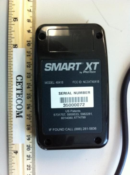
Click to zoom
Application Details
- Equipment Class
- DSR - Part 15 Remote Control/Security Device Transceiver
- Date of Grant
- Apr 27, 2011
- Application Purpose
- Original Equipment
- Date of Application
- Apr 27, 2011
- Equipment Note
- Offender Tracking Device
- Frequency Range
- 433.00000000 - 433.00000000
- Country
- United States
Documents & Files
Document Text
Text extracted from the exhibit documents filed with the FCC. Open a document above to read the original.
Users Manual
Pro Tech Monitoring Inc. Issue Date: 4/14/2011 Please check online for the most up to date version. 0 Pro Tech Monitoring Inc. Issue Date: 4/14/2011 Please check online for the most up to date version. 1 Table of Contents Overview........................................................................................................................................ - 2 - XT Details ...................................................................................................................................... - 3 – XT Features .................................................................................................................................... - 5 – Bracelet Details ............................................................................................................................... - 6 - SMART Base Details ......................................................................................................................... - 7 - Enrollment ....................................................................................................................................... -8- Enroll a Contact ............................................................................................................................ - 9- Contact Information Page ........................................................................................................... ..- 12 - Enroll an Offender ....................................................................................................................... - 13 - Supervision Level .......................................................................................................................... -14- Map Offender’s Address ................................................................................................................ - 17- Offender General Information Page ................................................................................................. - 18- Create Schedule for Home Inclusion Zone .......................................................................................... - 19- Create Exclusion Zone ..................................................................................................................... - 23- Activating the XT with the SMART Base .............................................................................................. - 27- Deactivating Hardware .................................................................................................................... - 31 - Removing the Bracelet .................................................................................................................... - 35– Accessing the Officer Menu ............................................................................................................. - 37 – Accessing the Offender Menu ........................................................................................................... - 38 - Appendix ....................................................................................................................................... - 39– Violation Definitions ........................................................................................................................ - 39– XT Status Icons ............................................................................................................................ - 41 – Safety and Precautions .................................................................................................................. - 42 – Pro Tech Monitoring Inc. Issue Date: 4/14/2011 Please check online for the most up to date version. 2 Overview Pro Tech’s SMART ® XT utilizes GPS satellites to establish an offender’s location and uses cellular networks to transmit the location data to Pro Tech. The SMART ® XT transmits all GPS data wirelessly at the agency’s contract specific call-in intervals. The SMART ® XT consists of four components: The Ankle Bracelet, the XT, the SMART ® Base, the optional carrying pouch accessory, and the SMART ® View software. Ankle Bracelet • Serves as an electronic tether to the SMART ® XT. SMART ® XT • A 6 oz. device, approximately the size of a Blackberry. The SMART ® XT receives transmitted information from GPS Satellites and Pro Tech’s ankle bracelet, and then uses its modem to transmit the data to Pro Tech by using the cellular network. SMART ® Base • A stationary device used to recharge the XT and transmits all information via a landline, if available. It also monitors the Ankle Bracelet when the SMART ® XT is placed in the SMART ® Base (docked). SMART ® View • The tracking and monitoring software that can be installed on almost any computer with Internet access. SMART ® View provides access to maps, offender information, and reports. Pro Tech Monitoring Inc. Issue Date: 4/14/2011 Please check online for the most up to date version. 3 XT Details Storing GPS Points: The storage of GPS points is based on an offender’s mobility. The XT will record and store GPS points based on the offender’s amount of activity. The XT will store an offender’s location, point, when it is in motion (moving) every minute. If the XT is left in the same place for 10 consecutive minutes without any motion, the XT will go to “Rest” and collect a point at the top of every hour instead of every minute. If the offender causes a Zone violation, the XT will store a point every 15 seconds. At Rest: If the XT is left in the same place for 10 consecutive minutes without any motion, the XT will go to “Rest” and collect a point at the top of every hour instead of every minute. This feature is designed to conserve the battery life. While the XT is at rest, it will still be communicating with the bracelet and ensuring that the offender is in range of the XT. Sim Card: The XT has a SIM card, which is similar to the data transmitter/receiver found in most cellular phones. The XT uses the SIM card to transmit and downlo…
Text truncated - open the document above for the full version.
Block Diagram
XT Block Diagram - 40433U .,...,&t*mlo.Froffi $r, ..: . *'''ffi Navman Jupiter 32xLP GPS Module U-Blox LEON GS-100 GSM Modem Module 1572MHz GPS Antenna And LNA 433 MHz ISM Antenna It; Chris Defant PRO TECH MONITORING, lNC.. 1838 GUNN HIGHWAY. ODESSA, FL 33556 PHON E I 1 3.749.5 454 . 888.67. SMART . FAX 8 1 3.7 49.547 4 www:ptm.com
Cover Letter(s)
March 25,2011 Federal Communications Commission Authorization and Evaluation Division Confidentiality Request regarding application for certification of FCC ID: NC3XT40433 Pursuant to Sections 0.457 and 0.459 of the Commission's Rules, we hereby request confidential treatment of information accompanying this application as outlined below: Exhibit Type Schematic Diagrams Bill of Materials (BOM) File Name XT Schematic.pdf XT BOM.pdf Pro Tech Monitoring develops equipment to monitor criminal offenders. Offenders are given operational instructions from their probation officer who is trained by Pro Tech personnel. In addition, the above materials contain trade secrets and proprietary information not customarily released to the public. The public disclosure of these materials may be harmful to the applicant and provide unjustified benefits to its competitors. The applicant understands that pursuant to Sectio n 0.457 of the Rules, disclosure of this application and all accompanying documentation will not be made before the date of the Grant for this application. Sincerelv. PRO TECH MONITORING, lNC.. 1838 GUNN HIGHWAY'ODESSA, FL 33556 PHON E 8'l 3.7 49.5454 . 888.67. SMART' FAX I 1 3.7 49.547 4 www.Ptm.com
External Photos
Model: 40443U FCC ID: NC3XT40433
Internal Photos
Model: 40433U FCC ID: NC3XT40433
Operational Description
Pro Tech Monitoring, Inc ▪ 1838 Gunn Hwy ▪ Odessa, FL 33556 Phone 813.749.5454 ▪ 888.67.SMART ▪ Fax 813.749.5474 www.ptm.com 40433U Operational Description Introduction The XT (model number 40433U) was designed to help probation and parole officers mo nitor offenders. The offender carries the XT and a bracelet transmitter that is attached to his ankle. The bracelet transmitter provides an electronic tether. The bracelet transmitter communicates with the XT via the UHF transceiver operating at 433MHz. The XT collects GPS positional information and compares this data to rules that have been established by a probation or parole officer. These rules geographically define where an offender is allowed or not allowed to go. The XT also includes hardware to determine if it has been tampered with and a GSM handset for receiving voice calls from the probation officer. System Overview The XT utilizes GPS to establish an offender’s location. Positional data (points) are stored every minute while the offender is not in violation of any rule and every 15 seconds whenever he or she is in violation. The cellular network (GPRS) is used to transmit the data back to servers at Pro Tech’s data center located in Odessa, FL. LCD Charging Port Response Buttons Pro Tech Monitoring, Inc ▪ 1838 Gunn Hwy ▪ Odessa, FL 33556 Phone 813.749.5454 ▪ 888.67.SMART ▪ Fax 813.749.5474 www.ptm.com The XT is comprised of the following subsystems: 1. GPS Receiver and Antenna 2. GSM\GPRS cellular modem (Quad Band GSM/GRPS MS Class 10, GPRS Capability Class B, Power class 4 for GSM/EGSM bands, Power class 1 for DCS/PCS bands, Voice and Data) 3. UHF transceiver and antenna operating at 433MHz (timing diagram is attached to Declaration of Conformance) 4. Microprocessor running application software and memory 5. Battery and battery charging circuit 6. Tamper detection circuit. 7. Response pushbuttons for offender acknowledgements. Both the GPS receiver and cellular modem are off-the-shelf modules. Weight: 0.173 Kg Size: 11 x 6.75 x 0.75 cm Operating Temperature: 0° to 50°C Battery Type: Lithium Ion ____________________ J. Chris Defant Declaration of Conformance This device does not contain a manually operated transmitter. The automaticallv activated transmitter ceases transmission within 5 seconds after activation. This is a security or safety application. This device transmits at regular predetermined intervals. The total duration of transmissions does not exceed more than two seconds per hour. The total transmission time does not exceed two seconds per hour. Transmitter Timing 433 MHz X sec \t----1,, 6 msec +/- 2 msec X+15sec AN ( t--"-] ) \f-___1,, 6 msec +/- 2 msec X+30sec /'--*N \I-*-*r,/ 6 msec +/- 2 msec J.{Chris Defant VP Engineering Pro Tech Monitoring PRO TECH MONITORING, lNC.. 1838 GUNN HIGHWAY. ODESSA, FL 33556 PHONE 813.749.5454. 888.67.SMART . FAX 81 3.749.5474 www.ptm.com
Test Report
Bluetooth Qualification Test Facility (BQTF) FCC listed A2LA Accredited IC recognized # 3462B CETECOM Inc. 411 Dixon Landing Road Milpitas, CA 95035 U.S.A. Phone: + 1 (408) 586 6200 Fax: + 1 (408) 586 6299 E-mail: [email protected] http://www.cetecom.com CETECOM Inc. is a Delaware Corporation with Corporation number: 2113686 Board of Directors: Dr. Harald Ansorge, Hans Peter May V3.0 2010-10-30 The BLUETOOTH trademarks are owned by Bluetooth SIG, Inc., U.S.A. and licensed to CETECOM Inc. © Copyright by CETECOM FCC Test Report FOR: Model Name: 40433U Two-piece offender tracking device containing a low power, high sensitivity GPS receiver and a wireless U-Blox LEON G200 GSM/GPRS modem. FCC ID: NC3XT40433 47 CFR Part 15.231 TEST REPORT #: EMC_PROTC_005_11001_FCC15.231_40433_Rev1 DATE: 2011-04-25 Test Report #: EMC_ PROTC_005_11001_FCC15.231_40433_Rev1 FCC ID: NC3XT40433 Date of Report : 2011-04-25 Page 2 of 29 TABLE OF CONTENTS 1 Assessment ......................................................................................................................................... 4 2 Administrative Data .......................................................................................................................... 5 2.1 Identification of the Testing Laboratory Issuing the EMC Test Report ................................................... 5 2.2 Identification of the Client ........................................................................................................................ 5 2.3 Identification of the Manufacturer ............................................................................................................ 5 3 Equipment under Test (EUT) .......................................................................................................... 6 3.1 Specification of the Equipment under Test .............................................................................................. 6 3.2 Identification of the Equipment Under Test (EUT) .................................................................................. 6 3.3 Identification of Accessory equipment ..................................................................................................... 6 4 Subject of Investigation .................................................................................................................... 7 5 Summary of Measurement Results .................................................................................................. 8 6 Measurements .................................................................................................................................... 9 6.1 Radiated Measurement Procedure ............................................................................................................ 9 6.2 Conducted Measurement Procedure ....................................................................................................... 11 6.3 Transmitter Fundamental Field Strength ................................................................................................ 12 6.3.1 Limits: ................................................................................................................................................. 12 6.3.2 Test Conditions: .................................................................................................................................. 12 6.3.3 Test Data: ........................................................................................................................................... 13 6.4 Transmitter 20dB Bandwidth .................................................................................................................. 14 6.4.1 Limits: ................................................................................................................................................. 14 6.4.2 Test Conditions: .................................................................................................................................. 14 6.4.3 Test Data: ........................................................................................................................................... 14 6.5 Transmitter Timeout ............................................................................................................................... 15 6.5.1 Limits: ................................................................................................................................................. 15 6.5.2 Test Conditions: .................................................................................................................................. 15 6.5.3 Test Data: ........................................................................................................................................... 15 6.6 Transmitter Duty Cycle ........................................................................................................................... 17 6.6.1 Reference: ........................................................................................................................................... 17 6.6.2 Test Conditions: .................................................................................................................................. 17 6.6.3 Test Data: ........................................................................................................................................... 17 6.7 Transmitter Spurious Emissions- Radiated ............................................................................................. 18 6.7.1 References: ......................................................................................................................................... 18 6.7.2 Measurement requirements: ............................................................................................................... 18 6.7.3 Limits: ....................................................…
Text truncated - open the document above for the full version.
Test Setup Photos
V2.0 2009-10-30 The BLUETOOTH trademarks are owned by Bluetooth SIG, Inc., U.S.A. and licensed to CETECOM Inc. © Copyright by CETECOM Test Setup Pictures TEST REPORT #: EMC_PROTC_005_11001_PIC_40433U Project #: EMC_PROTC_005_11001_PIC_40433U FCC ID: NC3XT40318 Date: 2011-04-25 Page 2 of 4 EIRP Test Setup Pictures FCC22_24 Project #: EMC_PROTC_005_11001_PIC_40433U FCC ID: NC3XT40318 Date: 2011-04-25 Page 3 of 4 Radiated Spurious Emissions Test Setup Pictures 30-1MHz Project #: EMC_PROTC_005_11001_PIC_40433U FCC ID: NC3XT40318 Date: 2011-04-25 Page 4 of 4 1-18MHz
Contact Information
Applicant
Daniel Williamson(Electronics/RF Engineer Tech)
Test Firm
CETECOM Inc.Meinolf Glunz
[email protected]408-586-6301
Technical Specifications
| # | Rule Parts | Frequency Range | Power Output |
|---|---|---|---|
| 1 | 15.231(e) | 433 MHz - 433 MHz | - |
Other Applications from Allied Universal Electronic Monitoring US, Inc.
NC3-25005AVL
Jan 13, 2026GPS Tracking Device
Equipment Class
DXX - Part 15 Low Power Communication Device TransmitterNC3TRACKER-100
Apr 16, 2024Tracker 100
Equipment Class
DTS - Digital Transmission System
NC3BEACON-100
Feb 18, 2024Beacon-100
Equipment Class
DXX - Part 15 Low Power Communication Device Transmitter
NC3HUB-300
Feb 07, 2024Home comunication unit
Equipment Class
DTS - Digital Transmission System
NC3-24074AVL
Jul 22, 2021GPS Tracking System (RTC)
Equipment Class
DSR - Part 15 Remote Control/Security Device Transceiver