NCBSL8500Spread Spectrum Transmitter
Wave Wireless Networking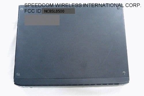
Click to zoom
Application Details
- Equipment Class
- DSS - Part 15 Spread Spectrum Transmitter
- Date of Grant
- Mar 31, 2002
- Application Purpose
- Original Equipment
- Date of Application
- Mar 31, 2002
- Equipment Note
- Spread Spectrum Transmitter
- Frequency Range
- 5745.00000000 - 5791.00000000
- Company
- Wave Wireless Networking
- Country
- United States
Documents & Files
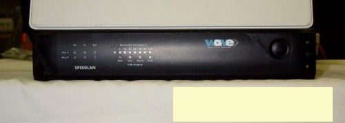
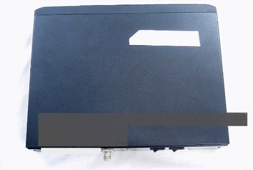
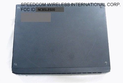
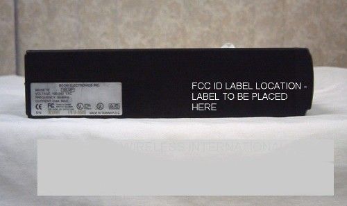
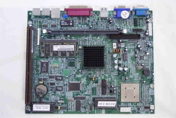
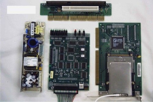
Document Text
Text extracted from the exhibit documents filed with the FCC. Open a document above to read the original.
Users Manual
SPEEDLAN 8300/8350 & 8400/8450 Installation and Operation User Guide -1 Version 1.0 / Last Revised August, 2000 Wave Wireless Networking a SPEEDCOM Wireless Company 1748 Independence Blvd. C-5 Sarasota, FL 34234 941-358-9283 www.speedlan.com SPEEDLAN 8500 Series Installation and Operation User Guide Version 1.1 / Last Revised March 21, 2002 Wave Wireless Networking a SPEEDCOM Wireless Company 7020 Professional Parkway East Sarasota, FL 34240 941-907-2300 www.wavewireless.com SPEEDLAN 8300/8350 & 8400/8450 Installation and Operation User Guide -2 Wave Wireless Networking Copyright Statement SPEEDLAN® 8500. Copyright © 2001. Wave Wireless Networking.™ All rights reserved. SPEEDLAN and SPEEDCOM are registered trademarks of Wave Wireless Networking. Wave Wireless Networking and the Wave Wireless Networking logo are trademarks of Wave Wireless Networking. All other company and product names may be trademarks of their respec- tive companies. SPEEDLAN 8500 Series Installation and Operation User Guide Contents-1 Chapter 1 - Introduction .................................................................................. 1-1 Product Description and Contents................................................................................................1-2 SPEEDLAN 8530 Complete Multipoint System ...............................................................1-2 SPEEDLAN 8250 Building-to Building System ................................................................1-2 SPEEDLAN 8510 to Add On to a Multipoint System .......................................................1-3 Installation Kit Contents ...............................................................................................1-3 Product Features ........................................................................................................................1-3 SPEEDLAN 8500 IDU Features ............................................................................................1-3 ISP Functionality ..........................................................................................................1-3 Transparent Ethernet Bridging with Advanced Filtering for Security and Network Reliability.1-4 IP Routing with Advanced Filtering for Security ...............................................................1-4 Wireless Multipoint Protocol .........................................................................................1-4 SNMP Management ....................................................................................................1-4 Additional Functionality ...............................................................................................1-4 SPEEDLAN SNMP Features...........................................................................................1-5 ISP Features................................................................................................................1-5 IP-Router Features .......................................................................................................1-5 Encryption Features (Add-on Option) ............................................................................1-5 SPEEDLAN 8500 Indoor Unit (IDU) ......................................................................................1-5 SPEEDLAN 8500 Outdoor Unit (ODU) .................................................................................1-6 Chapter 2 - Quick Start .................................................................................... 2-1 Rooftop and Tower Installations Warning .....................................................................................2-2 Installation Steps ........................................................................................................................2-2 SPEEDLAN 8500 Instructions ...............................................................................................2-3 Installation Diagrams..................................................................................................................2-6 SPEEDLAN 8500 Series ODU ..............................................................................................2-6 Chapter 3 - Hardware ....................................................................................... 3-1 Drawings of Components ...........................................................................................................3-2 SPEEDLAN 8500 IDU (Front Panel) ......................................................................................3-2 SPEEDLAN 8500 IDU (Back Panel).......................................................................................3-3 SPEEDLAN 8500 ODU Hardware................................................................................................3-4 Antenna ....................................................................................................................................3-4 Flat Panel Antenna..............................................................................................................3-4 Restoring Factory Default Settings on the SPEEDLAN 8500 IDU......................................................3-5 Upgrading the Firmware .............................................................................................................3-6 Chapter 4 - Overview of Configurator ............................................................ 4-1 Installation and Setup .................................................................................................................4-2 Windows 95/98/NT 4.0 SPEEDLAN Configurator .................................................................4-2 Toolbar and Menus ....................................................................................................................4-2 File Menu ..........................................................................................................................4-2 Configuring a SPEEDLAN IDU ...................…
Text truncated - open the document above for the full version.
Cover Letter(s)
January 7, 2002 Federal Communications Commission Authorization and Evaluation Division 7435 Oakland Mills Road Columbia, MD 21046 RE: Confidentiality Request regarding application for certification of SPEEDCOM Wireless FCC Certification of SPEEDLAN 8500, FCC ID: NCBSL8500 To Whom It May Concern: Pursuant to Sections 0.457 and 0.459 of the Commission’s Rules, we hereby request confidential treatment of information accompanying this application as outlined below: Schematics of Teletronics UDC 5800 Schematics of Lucent Technologies Radio The above materials contain trade secrets and proprietary information not customarily released to the public. The public disclosure of these materials may be harmful to the applicant and provide unjustified benefits to its competitors. The applicant understands that pursuant to Section 0.457 of the Rules, disclosure of this application and all accompanying documentation will not be made before the date of the Grant for this application. Sincerely, Janusz Dyndul Product Certification Manager SPEEDCOM Wireless Corporation 941-358-9283 ext. 407 [email protected]
Operational Description
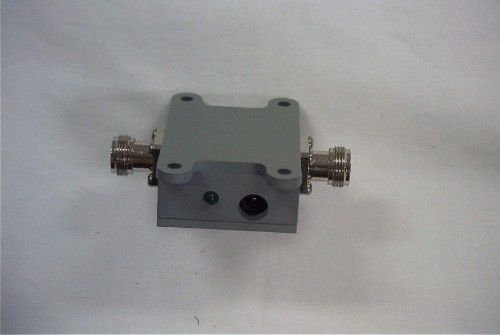
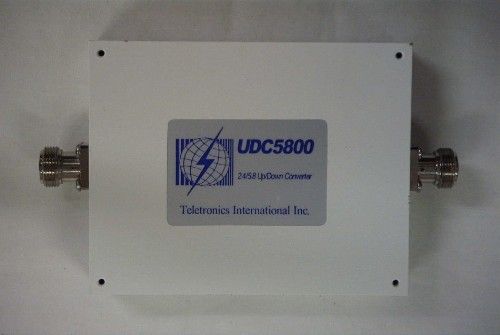
Operational description. Product overview This product is a Ethernet to RF transceiver. The product consists of a custom IBM compatible computer with a network interface controller card(NIC) and a Agere ORINOCO radio transceiver installed in a PCMIA port card. Attached to the RF output port is a up/down converter module to allow conversion to and from 5.6 GHz. The RF card: The unit uses multiple chipping codes and other special processes to achieve its high-speed rate. 1 Mb/s uses DBPSK, 2 Mb/s uses DQPSK, 5.5 Mb/s and 11Mb/s uses complementary code keying (CCK). The oscillators employed are a VCO from 2060 to 2100MHz controlled by software, 704 MHz, and which when divided by 2 gives the 352 MHz an IF local oscillator. The computer: The CPU uses a 33MHz oscillator. This unit contains all the necessary electronics to up/down convert the 5.6 GHz band to 2.4 GHz for use by the base unit. It is powered thru the coaxial cable using a mating DC inserter. The up/down converter uses a 3.3 GHz oscillator.
Test Report
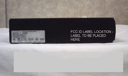
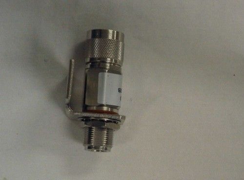
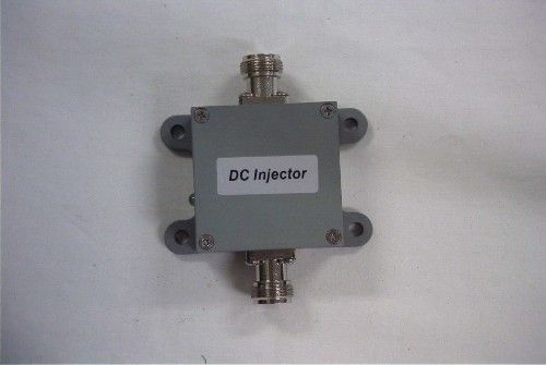
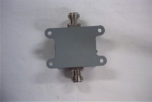
APPLICANT: WAVE WIRELESS NETWORKING FCC ID: NCBSL8500 REPORT #: W\WAVE_NCB\7UAT2-1\7UAT2-1RPT.doc TABLE OF CONTENTS LIST APPLICANT: WAVE WIRELESS NETWORKING FCC ID: NCBSL8500 TABLE OF CONTENTS TEST REPORT CONTAINING: PAGE 1.............LETTER OF EXPLANATION PAGE 2-5...........LIST OF TEST EQUIPMENT PAGE 6.............TEST PROCEDURES PAGE 7.............PRODUCT DESCRIPTION PAGE 8.............POWERLINE CONDUCTED INTERFERENCE PAGE 9-10..........POWERLINE CONDUCTED PLOTS PAGE 11.............OCCUPIED BANDWIDTH PAGE 12-14..........6 dB BANDWIDTH PLOTS PAGE 15.............POWER OUTPUT PAGE 16.............METHOD OF MEASURING RF CONDUCTED AND SPURIOUS EMISSIONS AT ANTENNA TERMINALS DATA PAGE 17-18..........RADIATION INTERFERENCE TEST DATA PAGE 19.............METHOD OF MEASURING RADIATED SPURIOUS EMISS. PAGE 20.............RADIATED SPURIOUS EMISSIONS INTO ADJACENT RESTRICTED BANDS PAGE 21.............POWER SPECTRAL DENSITY PAGE 22-24..........POWER SEPCTRAL DENSITY PLOTS EXHIBIT ATTACHMENTS: EXHIBIT 1...........REQUEST FOR CONFIDENTIALITY LETTER EXHIBIT 2...........FCC ID LABEL SAMPLE EXHIBIT 3...........SKETCH OF FCC ID LABEL LOCATION EXHIBIT 4A..........FRONT VIEW EXTERNAL PHOTO EXHIBIT 4B..........TOP VIEW EXTERNAL PHOTO EXHIBIT 4C..........BOTTOM VIEW EXTERNAL PHOTO EXHIBIT 4D..........SIDE VIEW EXTERNAL PHOTO EXHIBIT 4E-4F.......INTERNAL COMPONENT VIEW PHOTOS EXHIBIT 4G-4H.......INTERNAL SOLDER VIEW PHOTOS EXHIBIT 4I..........PHOTOGRAPH OF CONNECTOR EXHIBIT 4J-4M.......PHOTOGRAPHS OF DC INJECTOR EXHIBIT 4N-4P.......PHOTOGRAPHS OF AMPLIFIER EXHIBIT 5...........BLOCK DIAGRAM EXHIBIT 6...........SCHEMATICS - AMPLIFIER EXHIBIT 7...........ANTENNA INFORMATION EXHIBIT 8...........TEST SET UP PHOTO– RADIATED EXHIBIT 9...........TEST SET UP PHOTO – POWERLINE CONDUCTED EXHIBIT 10..........INSTRUCTION MANUAL EXHIBIT 11..........OPERATIONAL DESCRIPTION EXHIBIT 12..........SCHEMATICS OF LUCENT RADIO APPLICANT: WAVE WIRELESS NETWORKING FCC ID: NCBSL8500 REPORT #: W\WAVE_NCB\7UAT2-1\7UAT2-1RPT.doc Page 1 of 24 2/21/02 Federal Communications Commission Authorization and Evaluation Division 7435 Oakland Mills Road Columbia, MD 21046 SUBJECT: WAVE WIRELESS NETWORKING DIVISION OF SPEEDCOM WIRELESS CORP. FCC ID: NCBSL8500 To Whom It May Concern: The attached application is for a direct sequence spread spectrum assembly, made up of the Bridge/Radio (FCC ID: IMRWLPCE24H), 50 foot of coax, a UDC8500 Converter, 10 foot of coax, a lightning arrestor, and a planar array antenna. This system has only one type of antenna, a 5.8 GHz MTI MT-485002 Antenna 23 dBi gain. WAVE WIRELESS NETWORKING purchases standard antennas from the Manufacturer. The antenna is intended to be used outside and mounted on fixed permanent structures. The NCBSL8500 radio uses unique connectors (reverse TNC). The unit is designed to be professionally installed. Should you have any questions or require any further information with regards to this, please feel free to contact me. Sincerely, Mario R. de Aranzeta Engineer MRD/sh Encl. APPLICANT: WAVE WIRELESS NETWORKING FCC ID: NCBSL8500 REPORT #: W\WAVE_NCB\7UAT2-1\7UAT2-1RPT.doc Page 2 of 24 Equipment List DEVICE MFGR MODEL SERNO CAL/CHAR DATE DUE DATE or STATUS X 3-Meter OATS TEI N/A N/A Listed 12/22/99 12/22/02 3/10-Meter OATS TEI N/A N/A Listed 3/26/01 3/26/04 X Receiver, Beige Tower X Spectrum Analyzer (Tan) HP 8566B Opt 462 3138A07786 3144A20661 CAL 8/31/01 8/31/02 X RF Preselector (Tan) HP 85685A 3221A01400 CAL 8/31/01 8/31/02 X Quasi-Peak Adapter (Tan) HP 85650A 3303A01690 CAL 8/31/01 8/31/02 Receiver, Blue Tower Spectrum Analyzer (Blue) HP 8568B 2928A04729 2848A18049 CHAR 10/22/01 10/22/02 RF Preselector (Blue) HP 85685A 2926A00983 CHAR 10/22/01 10/22/02 Quasi-Peak Adapter (Blue) HP 85650A 2811A01279 CHAR 10/22/01 10/22/02 Biconnical Antenna Electro-Metrics BIA-25 1171 CAL 4/26/01 4/26/03 X Biconnical Antenna Eaton 94455-1 1096 CAL 10/1/01 10/1/02 Biconnical Antenna Eaton 94455-1 1057 CHAR 3/15/00 3/15/01 BiconiLog Antenna EMCO 3143 9409-1043 Log-Periodic Antenna Electro-Metrics LPA-25 1122 CAL 10/2/01 10/2/02 X Log-Periodic Antenna Electro-Metrics EM-6950 632 CHAR 10/15/01 10/15/02 Log-Periodic Antenna Electro-Metrics LPA-30 409 CHAR 10/16/01 10/16/02 Dipole Antenna Kit Electro-Metrics TDA-30/1-4 152 CAL 3/21/01 3/21/02 Dipole Antenna Kit Electro-Metrics TDA-30/1-4 153 CHAR 11/24/00 11/24/01 X Double-Ridged Horn Antenna Electro-Metrics RGA-180 2319 CAL 12/19/01 12/19/02 Horn Antenna Electro-Metrics EM-6961 6246 CAL 3/21/01 3/21/02 Horn Antenna ATM 19-443-6R None No Cal Required Passive Loop Antenna EMC Test Systems EMCO 6512 9706-1211 CHAR 7/10/01 7/10/02 Line Impedance Stabilization . . . Electro-Metrics ANS-25/2 2604 CAL 10/9/01 10/9/02 APPLICANT: WAVE WIRELESS NETWORKING FCC ID: NCBSL8500 REPORT #: W\WAVE_NCB\7UAT2-1\7UAT2-1RPT.doc Page 3 of 24 DEVICE MFGR MODEL SERNO CAL/CHAR DATE DUE DATE or STATUS Line Impedance Stabilization . . . Electro-Metrics EM-7820 2682 CAL 3/16/01 3/16/02 Termaline Wattmeter Bird Electronic Corporation 611 16405 CAL 5/25/99 (5/25/00) Termaline Wattmeter Bird Electronic Corporation 6104 1926 CAL 12/12/01 12/12/02 Oscilloscope Tektronix 2230 300572 CHAR 2/1/01 2/1/02 Temperature Chamber Tenney Engineering TTRC 11717-7 CHAR 1/22/02 1/22/03 AC Voltmeter HP 400FL 2213A14499 CAL 10/9/01 10/9/02 AC Voltmeter HP 400FL 2213A14261 CHAR 10/15/01 10/15/02 AC Voltmeter HP 400FL 2213A14728 CHAR 10/15/01 10/15/02 X Digital Multimeter Fluke 77 35053830 CHAR 1/8/02 1/8/03 Digital Multimeter Fluke 77 43850817 CHAR 1/8/02 1/8/03 Digital Multimeter HP E2377A 2927J05849 CHAR 1/8/02 1/8/03 Multimeter Fluke FLUKE-77-3 79510405 CAL 9/26/01 9/26/02 Peak Power Meter HP 8900C 2131A00545 CHAR 1/26/01 1/26/02 Digital Thermometer Fluke 2166A 42032 CAL 1/16/02 1/16/03 Thermometer Traulsen SK-128 CHAR 1/22/02 1/22/03 Temp/Humidity gauge EXTech 44577F E000901 CHAR 1/22/02 1/22/03 Frequency Counter HP 5352B 2632A00165 CAL 11/28/01 11/28/02 Power Sensor Agilent Technologies 84811A 2551A02705 CA…
Text truncated - open the document above for the full version.
Test Report
Nederland B.V. WCND FCC ID: WLPC24H/WLPCE24H Report No. 011734, Rev. B TEST REPORT Subject: Processing Gain For WaveLAN IEEE PC CARD type 2 HS Ref.: FCC Rules 47 CFR Part 15, Section 5.247d Report Prepared by: Maarten Visee May 6, 1999 Name Signature Date Concurrence: 1. Director of Engineering Bruce Tuch May 6, 1999 Name Signature Date 2. Team Captain Frans Hoekstra May 6, 1999 Name Signature Date FCC Processing Gain Measurements Results, FCCID WLPC24H/WLPCE24H, Report No. 011734, Rev. B. Lucent WCND Confidential ©1999 2 Lucent WCND Confidential Information ©1999 FCC Processing Gain Measurements Results, FCCID WLPC24H/WLPCE24H, Report No. 011734, Rev. B. Lucent WCND Confidential ©1999 i Date Section Description 04/16/99, Rev. A Initial release. 05/6/99, Rev. B 2 Changed spreading gain into processing gain. 4.1 For data rates of 5.5 and 11 Mbit/s changed processing gain requirements of 9 dB into 10 dB. 4.2 Changed description for demodulated data availability at the interconnection between RF and DSP into the interconnection between DSP and digital circuits. Changed spreading gain into processing gain. 7.2, 7.3 Changed sub sections Measurement Results and Measurement Conclusion. Annex A Updated flow chart. Change History: FCC Processing Gain Measurements Results, FCCID WLPC24H/WLPCE24H, Report No. 011734, Rev. B. Lucent WCND Confidential ©1999 1 This document describes the Receiver Processing Gain verification measurements performed at the WaveLAN-II PC-Card Type 2, according to Ref.[2]. The Lucent WaveLAN-II PC-Card Type 2 product confirms to the minimum required 10 dB processing gain, as set forth by the FCC for operation in the 2.4 GHz ISM band. 1- Document FCC 97-114, Appendix C, Guidance on Measurements for Direct Sequence Spread Spectrum Systems. 2- Hardware Functional Specification for WaveLAN-II Embedded, High Speed, Doc. No. 011735, Rev. A, Source Organization Lucent Technologies WCND Utrecht. 3- Viterbi, A. J., Principles of Coherent Communications, New York, McGraw-Hill 1966. 4- Proakis, J.G., Digital Communications, New York, McGraw-Hill 1989, page 270. 4.1 Test introduction - FCC requirements: Part of FCC certification for the Lucent WaveLAN IEEE 802.11 High Speed compliant Network Interface Card (NIC) is a processing gain test. This test proves that the receiver of the tested product employs a true spread spectrum device receiver structure, taking full advantage of the direct sequence spread spectrum modulation technique. This test verifies the receiver processing gain to be 10 dB or more for a data rate of 1, 2, 5.5 and 11 Mbit/s, by monitoring the Bit Error Rate (BER) of the product under test for each data rate, while operating under strict defined received signal conditions. Several methods of showing compliance to the rules are possible, from a stepped CW jammer to a continuous sweeping CW interferer. For this test the discrete stepped CW jammer method was chosen, as described in Ref.[1]. 1.Summary: 2.Conclusion: 3.References: 4.Measurement description: FCC Processing Gain Measurements Results, FCCID WLPC24H/WLPCE24H, Report No. 011734, Rev. B. Lucent WCND Confidential ©1999 2 Therefore a receiver input signal is applied to the product under test, in the presence of a Continuous Wave (CW) interference source, also referred to as CW jammer. The test takes place at the product Functional Specification (Ref.[2]) specified conditions for BER rate measurements, specifying a BER equal or better than 10^-8 at a receiver input level of -55 dBm. For practical reasons these test are performed at -55 dBm or -53 dBm. This small deviation from the Functional Specification should not cause any deviation from the specified Bit Error Rate, since the received levels are well above the thermal noise. The test criteria for meeting the minimal processing gain is such that it takes the theoretical calculated SNR for the applied modulation technique and specified BER as a reference. From this given SNR the processing gain is subtracted, yielding the CW Jammer to Signal ratio J/S. From Ref. [4], likewise as Ref.[3] consulted in Ref. [1], it is determined that for a BER of 10^-8 the SNR (S/N)o equals: 13 dB @ 1 Mbit/s, 15 dB @ 2 Mbit/s, 15 dB @ 5.5 Mbit/s, 18 dB @ 11 Mbit/s. Thus the J/S ratio for a processing gain of 10 dB that must be met is calculated as: -13 + 10 = -3 dB @ 1 Mbit/s (DBPSK), -15 + 10 = -5 dB @ 2 Mbit/s (DQPSK), -15 + 10 = -5 dB @ 5.5 Mbit/s (CCK), -18 + 10 = -8 dB @ 11 Mbit/s (CCK). Two types of measurement corrections are allowed for as described in Ref.[1]. The first taking into account 2 dB implementation losses, thus increasing the absolute J/S ratio by 2 dB. The second correction allows for deleting the 20% worst- case frequencies in the processing gain test that causes the test at that CW interference to fail. This implies that for the considered 14 MHz wide measurement interval the worst case 57 CW jammer frequencies can be ignored, being those that result in FCC Processing Gain Measurements Results, FCCID WLPC24H/WLPCE24H, Report No. 011734, Rev. B. Lucent WCND Confidential ©1999 3 received data errors/missing frames (20% of 14 MHz *(1 MHz/50 KHz) + 1 = (20% * 281) + 1 = 57). FCC Processing Gain Measurements Results, FCCID WLPC24H/WLPCE24H, Report No. 011734, Rev. B. Lucent WCND Confidential ©1999 4 4.2 Test sequence: The measurements are performed at a 50 KHz CW jammer raster. For each CW jammer frequency 10^8 bits are transmitted by the reference transmitter, and received by the product under test. For practical reasons 50.000 messages are transmitted. After blanking out frame overhead 1927 bits per frame are monitored. This results in 50.000 * 1927 = 9650000 transmitted bits for a BER test, which is a mere 1.4% less than the targeted 10^8 bits. Though it would be more elegant to show BER compliance for at least say ten times 10^8 transmitted/received bits, the time involved with this grows significantly. Since the CW interferer is stepped in a 50 KHz raster, cov…
Text truncated - open the document above for the full version.
Test Report
Measurement file output name is: 5mbit.cnd Input command file name is: INPUT.CMD Note: 5.5 Mbit, 6 dB SIR tested for ( 15 dB SNR - 10.4 + 1 impl. losses). Input CW correction level: 6 dB Takes into account 1 dB of implementation loss (allowed 2 dB). Lowcount is: 1000 messages Only RxD errors are taken into account since these need better SIR then preamble at 1 MBit Highcount is: 50000 messages Attention: Input the red cells for correct spreadsheet calculations! total errors 45 out of 280 measurement points. Rx level DUT is: -53 dBm percentage 16.07% Number of received data errors as a function of frequency and interference level OK? =<20%, OK Not measured combinations listed as "-1" HIJKLMN O PQ RS Uncorrected Interference level dialed at CW generator -60 -59 -58 -57 -56 -55 -54 -53 -52 RxD Errors PDA RxD Errors PDA Both error True CW interference level at receiver input (dBm) detected missing detected missing RxD and -66 -65 -64 -63 -62 -61 -60 -59 -58 full test full test up to CW AT CW PDA J/S ratio (dB) -13 #PDA -12 #PDA -11 #PDA -10 #PDA -9 #PDA -8 #PDA -7 #PDA -6 #PDA -5 #PDA range range =< -59 dBm = -59 dBm =< -59 dBm Frequency (Hz) (J/S = -5-1 dB) (J/S = -5-1 dB) time date 2409000000 0 1000 0 1000 0 1000 0 1000 0 1000 0 1000 0 1000 0 1000 0 50000 OK, 0 RxD error s OK, No PDA err o 000 15:53:49 4/15/99 2409050000 0 1000 0 1000 0 1000 0 1000 0 1000 0 1000 0 1000 0 1000 0 50000 OK, 0 RxD error s OK, No PDA err o 000 15:52:18 4/15/99 2409100000 0 1000 0 1000 0 1000 0 1000 0 1000 0 1000 0 1000 0 1000 0 50000 OK, 0 RxD error s OK, No PDA err o 000 15:50:48 4/15/99 2409150000 0 1000 0 1000 0 1000 0 1000 0 1000 0 1000 0 1000 0 1000 0 50000 OK, 0 RxD error s OK, No PDA err o 000 15:49:19 4/15/99 2409200000 0 1000 0 1000 0 1000 0 1000 0 1000 0 1000 0 1000 0 1000 0 50000 OK, 0 RxD error s OK, No PDA err o 000 15:47:48 4/15/99 2409250000 0 1000 0 1000 0 1000 0 1000 0 1000 0 1000 0 1000 0 1000 0 50000 OK, 0 RxD error s OK, No PDA err o 000 15:46:19 4/15/99 2409300000 0 1000 0 1000 0 1000 0 1000 0 1000 0 1000 0 1000 0 1000 0 50000 OK, 0 RxD error s OK, No PDA err o 000 15:44:49 4/15/99 2409350000 0 1000 0 1000 0 1000 0 1000 0 1000 0 1000 0 1000 0 1000 0 50000 OK, 0 RxD error s OK, No PDA err o 000 15:43:18 4/15/99 2409400000 0 1000 0 1000 0 1000 0 1000 0 1000 0 1000 0 1000 0 1000 0 50000 OK, 0 RxD error s OK, No PDA err o 000 15:41:49 4/15/99 2409450000 0 1000 0 1000 0 1000 0 1000 0 1000 0 1000 0 1000 0 1000 0 50000 OK, 0 RxD error s OK, No PDA err o 000 15:40:18 4/15/99 2409500000 0 1000 0 1000 0 1000 0 1000 0 1000 0 1000 0 1000 0 1000 0 50000 OK, 0 RxD error s OK, No PDA err o 000 15:38:48 4/15/99 2409550000 0 1000 0 1000 0 1000 0 1000 0 1000 0 1000 0 1000 0 1000 0 50000 OK, 0 RxD error s OK, No PDA err o 000 15:37:18 4/15/99 2409600000 0 1000 0 1000 0 1000 0 1000 0 1000 0 1000 0 1000 0 1000 0 50000 OK, 0 RxD error s OK, No PDA err o 000 15:35:48 4/15/99 2409650000 0 1000 0 1000 0 1000 0 1000 0 1000 0 1000 0 1000 0 1000 0 50000 OK, 0 RxD error s OK, No PDA err o 000 15:34:18 4/15/99 2409700000 0 1000 0 1000 0 1000 0 1000 0 1000 0 1000 0 1000 0 1000 0 50000 OK, 0 RxD error s OK, No PDA err o 000 15:32:48 4/15/99 2409750000 0 1000 0 1000 0 1000 0 1000 0 1000 0 1000 0 1000 0 1000 0 50000 OK, 0 RxD error s OK, No PDA err o 000 15:31:17 4/15/99 2409800000 0 1000 0 1000 0 1000 0 1000 0 1000 0 1000 0 1000 0 1000 0 50000 OK, 0 RxD error s OK, No PDA err o 000 15:29:47 4/15/99 2409850000 0 1000 0 1000 0 1000 0 1000 0 1000 0 1000 0 1000 0 1000 0 50000 OK, 0 RxD error s OK, No PDA err o 000 15:28:17 4/15/99 2409900000 0 1000 0 1000 0 1000 0 1000 0 1000 0 1000 0 1000 0 1000 0 50000 OK, 0 RxD error s OK, No PDA err o 000 15:26:46 4/15/99 2409950000 0 1000 0 1000 0 1000 0 1000 0 1000 0 1000 0 1000 0 1000 0 50000 OK, 0 RxD error s OK, No PDA err o 000 15:25:16 4/15/99 2410000000 0 1000 0 1000 0 1000 0 1000 0 1000 0 1000 0 1000 0 1000 0 50000 OK, 0 RxD error s OK, No PDA err o 000 15:23:45 4/15/99 2410050000 0 1000 0 1000 0 1000 0 1000 0 1000 0 1000 0 1000 0 1000 0 50000 OK, 0 RxD error s OK, No PDA err o 000 15:22:15 4/15/99 2410100000 0 1000 0 1000 0 1000 0 1000 0 1000 0 1000 0 1000 0 1000 0 50000 OK, 0 RxD error s OK, No PDA err o 000 15:20:45 4/15/99 2410150000 0 1000 0 1000 0 1000 0 1000 0 1000 0 1000 0 1000 0 1000 0 50000 OK, 0 RxD error s OK, No PDA err o 000 15:19:14 4/15/99 2410200000 0 1000 0 1000 0 1000 0 1000 0 1000 0 1000 0 1000 0 1000 0 50000 OK, 0 RxD error s OK, No PDA err o 000 15:17:44 4/15/99 2410250000 0 1000 0 1000 0 1000 0 1000 0 1000 0 1000 0 1000 0 1000 0 50000 OK, 0 RxD error s OK, No PDA err o 000 15:16:14 4/15/99 2410300000 0 1000 0 1000 0 1000 0 1000 0 1000 0 1000 0 1000 0 1000 0 50000 OK, 0 RxD error s OK, No PDA err o 000 15:14:43 4/15/99 2410350000 0 1000 0 1000 0 1000 0 1000 0 1000 0 1000 0 1000 0 1000 0 50000 OK, 0 RxD error s OK, No PDA err o 000 15:13:13 4/15/99 2410400000 0 1000 0 1000 0 1000 0 1000 0 1000 0 1000 0 1000 0 1000 0 50000 OK, 0 RxD error s OK, No PDA err o 000 15:11:42 4/15/99 2410450000 0 1000 0 1000 0 1000 0 1000 0 1000 0 1000 0 1000 0 1000 0 50000 OK, 0 RxD error s OK, No PDA err o 000 15:10:12 4/15/99 2410500000 0 1000 0 1000 0 1000 0 1000 0 1000 0 1000 0 1000 0 1000 0 50000 OK, 0 RxD error s OK, No PDA err o 000 15:08:42 4/15/99 2410550000 0 1000 0 1000 0 1000 0 1000 0 1000 0 1000 0 1000 0 1000 0 50000 OK, 0 RxD error s OK, No PDA err o 000 15:07:12 4/15/99 2410600000 0 1000 0 1000 0 1000 0 1000 0 1000 0 1000 0 1000 0 1000 0 50000 OK, 0 RxD error s OK, No PDA err o 000 15:05:42 4/15/99 2410650000 0 1000 0 1000 0 1000 0 1000 0 1000 0 1000 0 1000 0 1000 0 50000 OK, 0 RxD error s OK, No PDA err o 000 15:04:12 4/15/99 2410700000 0 1000 0 1000 0 1000 0 1000 0 1000 0 1000 0 1000 0 1000 0 50000 OK, 0 RxD error s OK, No PDA err o 000 15:02:42 4/15/99 2410750000 0 1000 0 1000 0 1000 0 1000 0 1000 0 1000 0 1000 0 1000 0 50000 OK, 0 RxD error s OK, No PDA err o 000 15:01:11 4/15/99 2410800000 0 1000 0 1000 0 1000 0 1000 0 1000 0 1000 0 1000 0 1000 0 50000 OK, 0 RxD …
Text truncated - open the document above for the full version.
Test Report
MTI part No.MT-485002 TypePlanar Array Regulatory ComplianceETSI EN 302 085 V1.1.2 (2001-02) ETS 300 019 part 1-4 Electrical Frequency Range5.15-5.85 GHz Gain23 dBi (min) VSWR1.5:1 (max) 3 dB BW Azimuth Elevation 9° (typ) 9° (typ) Polarization Linear (Vertical or Horizontal) Cross Polarization-20 dB (max) Sidelobe LevelETSI TS3 Range 1 F/B Ratio-32 dB (max) Lightning ProtectionDC Grounded Mechanical Dimensions (LxWxD)305 x 305 x 26 mm Weight1.5 kgs ConnectorN-Type Female* Temperature (operating)-40°C to +71°C Wind Load (Survival)220 km/hr Radial Ice Load25 mm Mounting KitMT-50001 (See Mounting Kit section) * Also available with SMA connector scriber AntennaubSGHz .8 5
Contact Information
Applicant
John Dyndul(Product Certification Manager)
Test Firm
Timco Engineering, Inc.S Sanders
Technical Specifications
| # | Rule Parts | Frequency Range | Power Output |
|---|---|---|---|
| 1 | 15C | 5.75 GHz - 5.79 GHz | 151.00 mW |
Other Applications from Wave Wireless Networking
NCBSL9101A
Dec 11, 2003Spread Spectrum Transmitter
Equipment Class
DTS - Digital Transmission System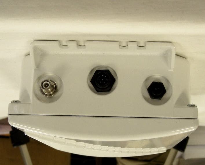
NCBSL9102A
Dec 09, 2003SPREAD SPECTRUM TRANSMITTER
Equipment Class
DTS - Digital Transmission System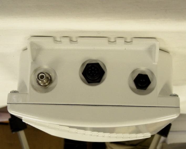
NCBSL9102
May 08, 2002Spread Spectrum Transmitter
Equipment Class
DTS - Digital Transmission System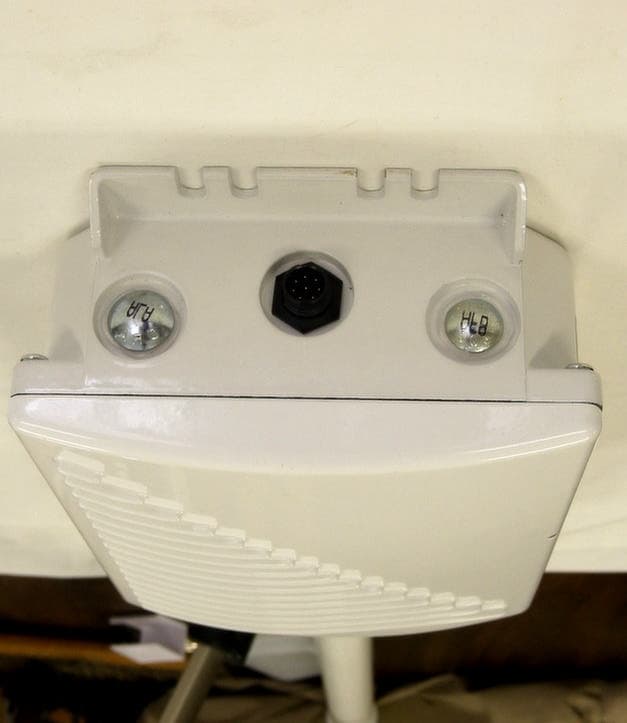
NCBSL9101
May 06, 2002Spread Spectrum Transmitter
Equipment Class
DTS - Digital Transmission System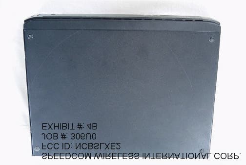
NCBSLXE2
Apr 11, 2002Spread Spectrum Transmitter
Equipment Class
DSS - Part 15 Spread Spectrum Transmitter