NCBSL9102ASPREAD SPECTRUM TRANSMITTER
Wave Wireless Networking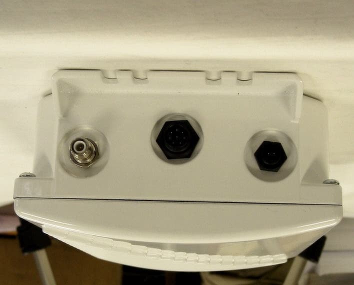
Click to zoom
Application Details
- Equipment Class
- DTS - Digital Transmission System
- Date of Grant
- Dec 09, 2003
- Application Purpose
- Original Equipment
- Date of Application
- Dec 09, 2003
- Equipment Note
- SPREAD SPECTRUM TRANSMITTER
- Frequency Range
- 2412.00000000 - 2462.00000000
- Company
- Wave Wireless Networking
- Country
- United States
Documents & Files
Document Text
Text extracted from the exhibit documents filed with the FCC. Open a document above to read the original.
Users Manual
A S P E E D C O M W I R E L E S S C O R P O R A T I O N S P E E D L A N 9 0 0 0 SPEEDLAN 9000 Series Installation and Operation User Guide Version 3.03 Last Revised: July 3, 2003 -1 Copyright/Liability Copyright ©2002, 2003. Wave Wireless Networking. All rights reserved. SPEEDCOM, SPEEDSignal and SPEEDView are registered trademarks of Wave Wireless Networking. SPEEDLAN, Wave Wireless Networking and the Wave Wireless Networking logo are trademarks of Wave Wireless Networking. All other trademarks mentioned in this document are the property of their respective owners. Contents of this publication may be preliminary and/or may be changed at any time without notice and shall not be regarded as a warranty. For more information, contact Wave Wireless Networking at: Wave Wireless Networking 7020 Professional Parkway East Sarasota, FL 34240 www.wavewireless.com Technical Support 941-907-2300 (phone) 941-355-0219 (fax) SPEEDLAN 9000 Series Installation and Operation User Guide Version 3.03 Contents-1 Chapter 1 - Introduction................................................................................... 1-1 Features and Benefits ................................................................................................................. 1-2 SPEEDLAN 9000 Series Features ......................................................................................... 1-2 ISP Functionality ................................................................................................................. 1-3 IP Router Functionality ........................................................................................................1-3 Network Management ........................................................................................................ 1-3 Features (and Benefits)........................................................................................................1-4 Equipment Features ................................................................................................................... 1-5 SPEEDLAN Polling Protocol -- How it Works ................................................................................ 1- 6 Point-to-Point Functionality.................................................................................................. 1-6 Point-to-Multipoint Functionality .......................................................................................... 1-6 SPEEDLAN 9000 Mesh Protocol -- How It Works in Mesh Clouds .................................................. 1-8 SPEEDLAN’s Mesh Cloud Architecture................................................................................ 1-10 SPEEDLAN 9000 Mesh Core Components ......................................................................... 1-10 Network Expansion: Connecting Buildings in a SPEEDLAN 9000 Network............................. 1-12 What’s New for Version 3.03....................................................................................................1-14 What’s New for Version 3.0......................................................................................................1-15 Contacting Technical Support ...................................................................................................1-18 Chapter 2 SPEEDLAN 9101, 9102, 9103 & 9104 Hardware ........................... 2-1 Rooftop and Tower Installations Warning ..................................................................................... 2-2 General Safety Requirements for Installation of SPEEDLAN 9000 Models........................................ 2-2 Hardware Overview ................................................................................................................... 2-3 Drawings of Outdoor, Remote-Mounted Components .................................................................. 2-4 Indoor Junction Box............................................................................................................2-4 The SPEEDLAN 9101(with an Integrated 8 dBi Omni)............................................................ 2-5 SPEEDLAN 9104 (with 5 dBi Omni) ..................................................................................... 2-6 Bottom View of SPEEDLAN 9101/9104................................................................................ 2-7 System Description .............................................................................................................2-7 Package Contents ............................................................................................................. 2-7 Installation Steps for the SPEEDLAN 9101/9104 ................................................................... 2-8 Installation Diagram of the SPEEDLAN 9101/9104............................................................. 2-10 The SPEEDLAN 9102 and 9103 (CPE and Base Station Use)....................................................... 2-12 As a 9102 CPE/Point-to-Point with Grid or Directional Antenna ........................................... 2-12 As a Base Station with Sectoral Antenna ............................................................................. 2-13 As a Base Station with High-Gain Omni Antenna................................................................ 2-14 Bottom View of SPEEDLAN 9102 and 9103 ....................................................................... 2-15 System Description ........................................................................................................... 2-15 Package Contents ............................................................................................................ 2-15 Installation Steps for the SPEEDLAN 9102 and 9103........................................................... 2-16 9102/9103 Installation Diagram....................................................................................... 2-22 Chapter 3 - General Functions of the Configurator ...........................…
Text truncated - open the document above for the full version.
Users Manual
SPEEDLAN 9000 Series Installation and Operation User Guide Version 3.03 Using the Configurator to Set Up Special Parameters for CPE Routers5-3 •Interface Type: Select the CPE from the Interface Type drop-down list. When finished, click Apply. This will tell the configurator that you are in CPE mode. •Network Name: The type of network for the wireless or fixed router. •Enable Forwarding: Select the Enable Forwarding option to enable the forwarding of IP packets from the wired interface to the wireless interface and vice-versa. •Disable Forwarding: Select the Disable Forwarding option to disable the forwarding of IP packets from the wired interface to the wireless interface and vice-versa. •Apply: Click after making changes. Base Station Information To see if a CPE is connected to the base station, choose Base Station Info from the Network menu. The following page will appear. Note: If there is no connection to the base station, a message will appear confirming that the CPE is not connected to the base station. Figure 5-2: Base Station Information (for CPE mode) Version 3.03 SPEEDLAN 9000 Series Installation and Operation User Guide 5-4Using the Configurator to Set Up Special Parameters for CPE Routers Authentication Normally, the CPE routers must prove their authenticity with a base station before participating in the star network. One way to do this is to set a common pass on both the CPE router and on the base station. Use this page (Authentication Settings) to set a pass phrase for a CPE router. You are only required to do this once, unless the pass phrase on the base station changes. Just make sure that the password is kept in a safe place so it is not lost or stolen. All interfaces connected to the 9000 router are restricted to systems based on the authentic pass phrase (or password). Any interface that does not have the correct pass phrase will not be able to establish a data connection. To authenticate a CPE, choose Authentication from the Network menu. The following page will appear. Figure 5-3: Authentication Settings for CPE page •Pass Phrase: Enter a pass phrase and confirm it like setting up a regular password. As shipped there would be a blank pass phrase and a base station authenticates CPE routers using the MAC address. If you want to use the Pass Phrase authentication, then you have to set matching pass phrases on a base SPEEDLAN 9000 Series Installation and Operation User Guide Version 3.03 Using the Configurator to Set Up Special Parameters for CPE Routers5-5 station and on a CPE. (Pass Phrases have a minimum of 8 characters and a maximum of 32 characters.) •Confirm: Enter the pass phrase again to ensure it is correct. Make sure you keep the pass phrase in a safe place. Wireless menu Choose Configuration from the Wireless menu and you will be able to choose one of the following: •If you click the Channel and Rates button, you will be able to select the channel and signaling rate of the interface. For more information, see Channel and Rates, page 5-6. •If you click the Tx Retries button, you will be able to set the Transmit Retry Limit and Signaling Rate Fallback. For more information, see Max Tx Retries and Signaling Rate Fallback, page 5-8. •If you click the Max Throughput button, you will be able to set the Max Transmit Data Rate in Kb/s. For more information, see Max Throughput (Regulating Bandwidth), page 5-10. Version 3.03 SPEEDLAN 9000 Series Installation and Operation User Guide 5-6Using the Configurator to Set Up Special Parameters for CPE Routers Channel and Rates Figure 5-4: Channel and Rates page •Primary Firmware: This is the current primary firmware version in use by the wireless card. •Station Firmware: This is the current station firmware version in use by the wireless card. •Channel: This is the specific band of frequencies (from 1 to 11) to determine the data path between routers. All SPEEDLAN 9000 routers expected to communicate in a network must have the same channel (frequency). Select one of the following channels (all are represented in GHz) from the Channel drop-down list: 12.412 22.417 32.422 42.427 52.432 62.437 72.442 version: v SPEEDLAN 9000 Series Installation and Operation User Guide Version 3.03 Using the Configurator to Set Up Special Parameters for CPE Routers5-7 82.447 92.452 102.457 112.462 •Signaling Rate: This setting refers to the wireless signaling rate. The SPEEDLAN 9000 routers have four signaling rates that can be used. Select one of the following check boxes: •1 Mb/s: This setting limits the card by providing 1 Mb/s of bandwidth. The minimum receiver sensitivity of the radio with this setting is -92 dBm. •2 Mb/s: This setting limits the card by providing 2 Mb/s of bandwidth. The minimum receiver sensitivity of the radio with this setting is -89 dBm. •5.5 Mb/s: This setting limits the card to providing 5.5 Mb/s of bandwidth. The minimum receiver sensitivity of the radio with this setting is -88 dBm. •11 Mb/s: This is the full 11 Mb/s signaling rate. This value is recommended for most installations. The minimum receiver sensitivity of the radio with this setting is -85 dBm. Note: The network can automatically downgrade the bandwidth if needed (that is, if lower Mb/s settings are selected). Click Apply when finished. Version 3.03 SPEEDLAN 9000 Series Installation and Operation User Guide 5-8Using the Configurator to Set Up Special Parameters for CPE Routers Max Tx Retries and Signaling Rate Fallback This page includes two features: Max Tx Retries and Signaling Rate Fallback. On the figure below, Max Tx Retries is circled in red and Signaling Rate Fallback is circled in blue. The following page appears when the Tx Retries button is clicked: Figure 5-5: Tx Retries and Signaling Rate Fallback page Note: Click Apply to activate settings. Max Tx Retries Wave Wireless recommends that you use this parameter to increase the throughput of your wireless network. This parameter tells a network node the maximum number of times a unicast frame c…
Text truncated - open the document above for the full version.
Block Diagram
Figure 1. Block Diagram of Wireless Outdoor Mount Ethernet NCBSL9102A Bridge To Ethernet - Cat5 CableTo 24 dBi Grid Antena 11 Mbps MiniPCI Adapter ( Transmitter / Receiver ) Junction Box Soekris net4501 Embedded Processor (CPU, Flash ROM Module, NIC Card) To Switching Power Supply 24 Vdc Voltage Regulator DC Voltage + Ethernet Cat5 Cable 12 Vdc Ethernet DC To Ground Lightning Arrestor Enclosure
Block Diagram
U11 Ethernet MAC/PHY National Semiconductor DP83815 U10 Buffer, hex 74LVC125 U14 Serial EEPROM 93C46 U2 SDRAM 16M x 16 U3 SDRAM 16M x 16 U17 RS-232 Transceiver MAX3243 (not used) X1 Crystal 32 MHz X2 Crystal 32.768 kHz U4 Flash Memory 128k x 8 SST 39VF010 U6 DC/DC Converter MAX1714 P1 Connector 9-pin D-sub X3 Crystal Oscillator 25 MHz U13 Ethernet MAC/PHY National Semiconductor DP83815 U15 Ethernet MAC/PHY National Semiconductor DP83815 U16 Serial EEPROM 93C46 U12 Serial EEPROM 93C46 T1 Ethernet Transformer & Filter T2 Ethernet Transformer & Filter T3 Ethernet Transformer & Filter U5 RS-232 Transceiver MAX3243 J1 Connector DC Power Input JP7 Modular Jack 8-position JP8 Modular Jack 8-position JP6 Modular Jack 8-position Q3 Dual FET IR147 BT1 Battery J2 Connector PCI Bus J3 Connector mini PCI JP2 Connector Compact Flash JP3 Connector Alt. Power U8 Voltage Regulator D3,6,10 LEDs JP1 Connector JTAG Debugger JP11 Connector 10-pin header (not used) JP3 Connector Parallel I/O PCI Bus Local Bus Controller SDRAM Bus Controller U1 MicroProcessor AMD Elan SC520 PCI Bus Controller UART1 UART2 JTAG Port MAC/PHY GPIO Real Time Clock Clock Gen Block Diagram: Soekris net4501 Single Board Computer
Cover Letter(s)
Federal Communications Commission Authorization and Evaluation Division 7435 Oakland Mills Road Columbia, MD 21046 RE: Confidentiality Request regarding application for certification of WAVE WIRELESS NETWORKING, FCC Certification of FCC ID: NCBSL9102A To Whom It May Concern: Pursuant to Sections 0.457 and 0.459 of the Commission’s Rules, we hereby request confidential treatment of information accompanying this application as outlined below: Schematics The above materials contain trade secrets and proprietary information not customarily released to the public. The public disclosure of these materials may be harmful to the applicant and provide unjustified benefits to its competitors. The applicant understands that pursuant to Section 0.457 of the Rules, disclosure of this application and all accompanying documentation will not be made before the date of the Grant for this application. Sincerely, Janusz Dyndul Product Certification Manager WAVE WIRELESS NETWORKING 941-358-9283 ext. 407 [email protected]
External Photos
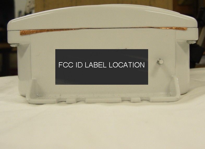
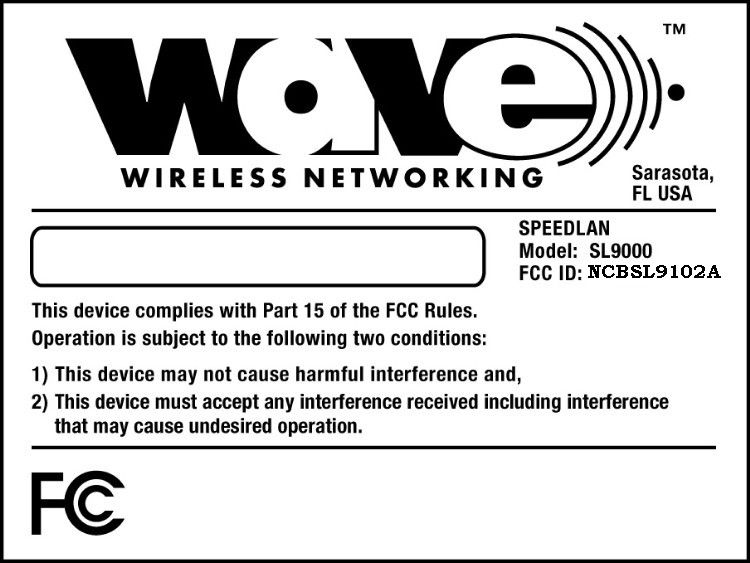
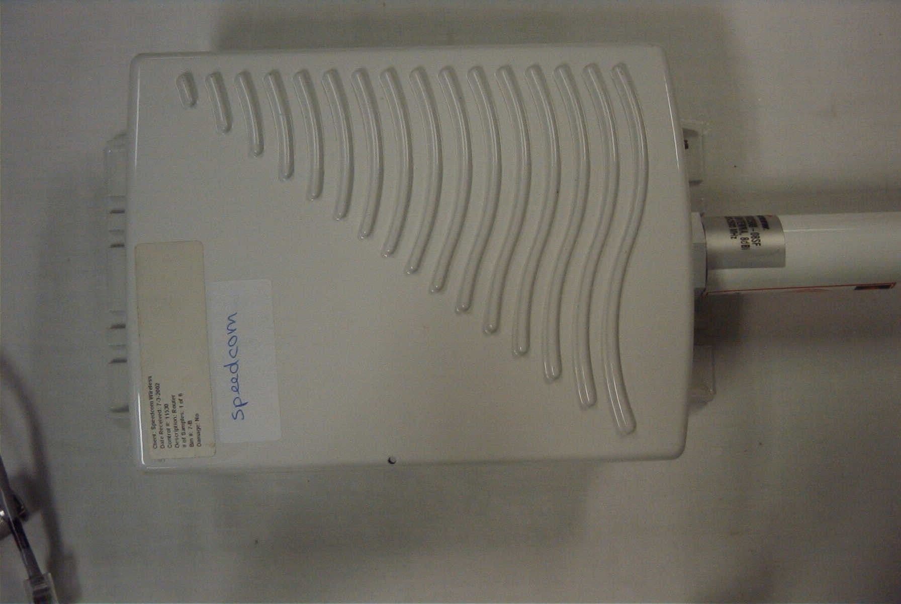
WAVE WIRELESS NETWORKING FCC ID: NCBSL9102 EXTERNAL PHOTOGRAPHS TOP VIEW EXTERNAL PHOTO BOTTOM VIEW EXTERNAL PHOTO EXTERNAL REAR VIEW PHOTO
External Photos
Page 10 Page 11
Operational Description
Operational Description of Wireless Outdoor Mount Ethernet Bridge SPEEDLAN 9000 Series The outdoor wireless Ethernet bridge, FCC ID: NCBSL9101A and NSBSL9102A is a high performance bridge / router that create interconnectivity between buildings and providing links for LAN-to-LAN applications. This system can be used in star or mesh configutation. The functional block diagram of the bridge is presented on Figure 1. The outdoor wireless Ethernet bridges are installed on the pole or tower. The bridge containing 11 Mb/s MiniPCI Adapter, Embedded Processor and Voltage Regulator is enclosed in metal enclosure connected to the ground. The Ethernet data and DC supply voltage (18 to 36 Vdc) are injected through junction box and to up to 300 feet long Cat 5 Ethernet cable ( 2 pairs are used for DC voltage and other 2 for Ethernet data ) and connected to the bridge. Than DC voltage is separated and connected to Voltage Regulator and Ethernet data are processed and transferred to WaveLan transmitter which is connected to 8 dBi omni or 24 dBi grid antenna . If system is not transmitting it is in receiving mode. The received signal from antenna is amplified, processed, demodulated and through Cat 5 Ethernet cable connected to LAN system. Technical Specification of SPEEDLAN 9000 Series Bridge Radio Type: Direct Sequence Spread Spectrum (DSSS) Frequency: 2400 – 2483.5 MHz (ISM Band) Channels: 11 Processing Gain: 11 dB (Nominal) Communication Method: Half-duplex Transmit Power: 15 dBm (Nominal) Receiver Sensivity: Max. –88 dBm (-80 at 11Mb/s) Bit Rate: 1 to 11 Mbit/sec Bit Error Rate: Better than 10E-5 Modulation: DBPSK at 1 Mbit/sec DQPSK at 2 Mbit/sec CCK at 5.5 and 11 Mbit/sec Spreading: 11 chip Barker sequence with chipping rate 1 Mbaud LAN Interface Compliance: IEEE 802.3 Ethernet Physical Interface: 10Base-T ,10/100Base-TX Ethernet Interface: 10 Mb/s Ethernet General: Power Supply: 18 to 36 Vdc 24 W Temperature Range: -40 to +70 C Humidity ( Non-immersion) 0 to 95 % Range: Up to 25 miles
Test Report
APPLICANT: WAVE WIRELESS NETWORKING FCC ID: NCBSL9102A REPORT #: W\WAVE_NCB\356UT3\356UT3TestReport.doc TABLE OF CONTENTS LIST APPLICANT: WAVE WIRELESS NETWORKING FCC ID: NCBSL9102A TABLE OF CONTENTS FOR A DIRECT SEQUENCE SPREAD SPECTRUM TEST REPORT CONTAINING: PAGE 1.............LETTER OF EXPLANATION PAGE 2-4...........LIST OF TEST EQUIPMENT PAGE 5.............TEST PROCEDURES PAGE 6.............PRODUCT DESCRIPTION PAGE 7.............POWERLINE CONDUCTED INTERFERENCE PAGE 8.............POWERLINE CONDUCTED PLOTS PAGE 9.............OCCUPIED BANDWIDTH AND POWER OUTPUT PAGE 10............6 dB BANDWIDTH PLOT PAGE 11............METHOD OF MEASURING RF CONDUCTED AND SPURIOUS EMISSIONS AT . ANTENNA TERMINALS DATA PAGE 12............RADIATION INTERFERENCE TEST DATA PAGE 13............CLASS B RADIATED EMISSIONS PAGE 14............METHOD OF MEASURING RADIATED SPURIOUS EMISS. PAGE 15............RADIATED SPURIOUS EMISSIONS INTO ADJACENT RESTRICTED BANDS PAGE 16-17.........BANDEDGE PLOTS PAGE 18............POWER SPECTRAL DENSITY PAGE 19............POWER SPECTRAL DENSITY PLOT EXHIBIT ATTACHMENTS: EXHIBIT 1...........REQUEST FOR CONFIDENTIALITY LETTER EXHIBIT 2...........FCC ID LABEL SAMPLE EXHIBIT 3...........SKETCH OF FCC ID LABEL LOCATION EXHIBIT 4...........EXTERNAL PHOTOGRAPHS EXHIBIT 5...........INTERNAL PHOTOGRAPHS EXHIBIT 6...........GEMTEK PHOTOGRAPHS EXHIBIT 7...........BLOCK DIAGRAM EXHIBIT 8...........SCHEMATIC EXHIBIT 8...........USERS MANUAL EXHIBIT 10..........OPERATION DESCRIPTION EXHIBIT 111.........TEST SETUP PHOTOGRAPHS APPLICANT: WAVE WIRELESS NETWORKING FCC ID: NCBSL9102A REPORT #: W\WAVE_NCB\356UT3\356UT3TestReport.doc Page 1 of 19 8/8/2003 Federal Communications Commission Authorization and Evaluation Division 7435 Oakland Mills Road Columbia, MD 21046 SUBJECT: WAVE WIRELESS NETWORKING FCC ID: NCBSL9102A To Whom It May Concern: The attached application is for a direct sequence spread spectrum assembly, made up of the Bridge/Radio mini PCI card (FCC ID: MXF-M900821),a custom case , power supply, a lightning arrestor, and a parabolic antenna. This system uses the same components except for the mini PCI as the NCBSL9102. It uses only one type of antenna, a parabolic grill type that has a gain of 24dBi. WAVE WIRELESS NETWORKING purchases standard antennas from the manufacturer. The antenna is intended to be used outside. The NCBSL9102A radio uses a unique connector (reverse TNC). Sincerely, Mario R. de Aranzeta C.E.T. MRD/sh Encl. APPLICANT: WAVE WIRELESS NETWORKING FCC ID: NCBSL9102A REPORT #: W\WAVE_NCB\356UT3\356UT3TestReport.doc Page 2 of 19 EMC Equipment List DEVICE MFGR MODEL SERNO CAL/CHAR DATE DUE DATE or STATUS X 3-Meter OATS TEI N/A N/A Listed 12/22/99 12/22/02 3/10-Meter OATS TEI N/A N/A Listed 3/26/01 3/26/04 Receiver, Beige Tower Spectrum Analyzer (Tan) HP 8566B Opt 462 3138A07786 3144A20661 CAL 8/31/01 8/31/03 RF Preselector (Tan) HP 85685A 3221A01400 CAL 8/31/01 8/31/03 Quasi-Peak Adapter (Tan) HP 85650A 3303A01690 CAL 8/31/01 8/31/03 X Receiver, Blue Tower X Spectrum Analyzer (Blue) HP 8568B 2928A04729 2848A18049 CHAR 10/22/01 10/22/03 X RF Preselector (Blue) HP 85685A 2926A00983 CHAR 10/22/01 10/22/03 X Quasi-Peak Adapter (Blue) HP 85650A 2811A01279 CHAR 10/22/01 10/22/03 X Biconnical Antenna Electro-Metrics BIA-25 1171 CAL 4/26/01 4/26/03 Biconnical Antenna Eaton 94455-1 1096 CAL 10/1/01 10/1/03 Biconnical Antenna Eaton 94455-1 1057 CHAR 3/15/00 3/15/02 BiconiLog Antenna EMCO 3143 9409-1043 X Log-Periodic Antenna Electro-Metrics LPA-25 1122 CAL 10/2/01 10/2/03 Log-Periodic Antenna Electro-Metrics EM-6950 632 CHAR 10/15/01 10/15/03 Log-Periodic Antenna Electro-Metrics LPA-30 409 CHAR 10/16/01 10/16/03 Dipole Antenna Kit Electro-Metrics TDA-30/1-4 152 CAL 3/21/01 3/21/04 Dipole Antenna Kit Electro-Metrics TDA-30/1-4 153 CHAR 11/24/00 11/24/03 Double-Ridged Horn Antenna Electro-Metrics RGA-180 2319 CAL 12/19/01 12/19/03 Horn Antenna Electro-Metrics EM-6961 6246 CAL 3/21/01 3/21/03 Horn Antenna ATM 19-443-6R None No Cal Required Passive Loop Antenna EMC Test Systems EMCO 6512 9706-1211 CHAR 7/10/01 7/10/03 Line Impedance Stabilization . . . Electro-Metrics ANS-25/2 2604 CAL 10/9/01 10/9/03 APPLICANT: WAVE WIRELESS NETWORKING FCC ID: NCBSL9102A REPORT #: W\WAVE_NCB\356UT3\356UT3TestReport.doc Page 3 of 19 DEVICE MFGR MODEL SERNO CAL/CHAR DATE DUE DATE or STATUS Line Impedance Stabilization . . . Electro-Metrics EM-7820 2682 CAL 3/16/01 3/16/03 Termaline Wattmeter Bird Electronic Corporation 611 16405 CAL 5/25/99 5/25/01 Termaline Wattmeter Bird Electronic Corporation 6104 1926 CAL 12/12/01 12/12/03 Oscilloscope Tektronix 2230 300572 CHAR 2/1/01 2/1/03 Temperature Chamber Tenney Engineering TTRC 11717-7 CHAR 1/22/02 1/22/04 AC Voltmeter HP 400FL 2213A14499 CAL 10/9/01 10/9/03 AC Voltmeter HP 400FL 2213A14261 CHAR 10/15/01 10/15/03 AC Voltmeter HP 400FL 2213A14728 CHAR 10/15/01 10/15/03 X Digital Multimeter Fluke 77 35053830 CHAR 1/8/02 1/8/04 Digital Multimeter Fluke 77 43850817 CHAR 1/8/02 1/8/04 Digital Multimeter HP E2377A 2927J05849 CHAR 1/8/02 1/8/04 Multimeter Fluke FLUKE-77-3 79510405 CAL 9/26/01 9/26/03 Peak Power Meter HP 8900C 2131A00545 CHAR 1/26/01 1/26/03 Digital Thermometer Fluke 2166A 42032 CAL 1/16/02 1/16/04 Thermometer Traulsen SK-128 CHAR 1/22/02 1/22/04 X Temp/Humidity gauge EXTech 44577F E000901 CHAR 1/22/02 1/22/04 Frequency Counter HP 5352B 2632A00165 CAL 11/28/01 11/28/03 Power Sensor Agilent Technologies 84811A 2551A02705 CAL 1/26/01 1/26/03 Service Monitor IFR FM/AM 500A 5182 CAL 11/22/00 11/22/02 Comm. Serv. Monitor IFR FM/AM 1200S 6593 CAL 5/12/02 5/12/04 Signal Generator HP 8640B 2308A21464 CAL 11/15/01 11/15/03 Modulation Analyzer HP 8901A 3435A06868 CAL 9/5/01 9/5/03 Near Field Probe HP HP11940A 2650A02748 CHAR 2/1/01 2/1/03 APPLICANT: WAVE WIRELESS NETWORKING FCC ID: NCBSL9102A REPORT #: W\WAVE_NCB\356UT3\356UT3TestReport.doc Page 4 of 19 DEVICE MFGR MODEL SERNO CAL/CHAR DATE DUE DATE or STATUS BandReject Filter Lorch Microwave 5BR4-2400/ 60-N…
Text truncated - open the document above for the full version.
Test Setup Photos
NCBSL9102A NCBSL9102A NCBSL9102A NCBSL9102A NCBSL9102A NCBSL9102A
Contact Information
Applicant
John Dyndul(Product Certification Manager)
Test Firm
Timco Engineering, Inc.S Sanders
Technical Specifications
| # | Rule Parts | Frequency Range | Power Output |
|---|---|---|---|
| 1 | 15C | 2.41 GHz - 2.46 GHz | 40.00 mW |
Other Applications from Wave Wireless Networking
NCBSL9101A
Dec 11, 2003Spread Spectrum Transmitter
Equipment Class
DTS - Digital Transmission System
NCBSL9102
May 08, 2002Spread Spectrum Transmitter
Equipment Class
DTS - Digital Transmission System
NCBSL9101
May 06, 2002Spread Spectrum Transmitter
Equipment Class
DTS - Digital Transmission System
NCBSLXE2
Apr 11, 2002Spread Spectrum Transmitter
Equipment Class
DSS - Part 15 Spread Spectrum Transmitter
NCBSL8500
Mar 31, 2002Spread Spectrum Transmitter
Equipment Class
DSS - Part 15 Spread Spectrum Transmitter