NCBSLXE2Spread Spectrum Transmitter
Wave Wireless Networking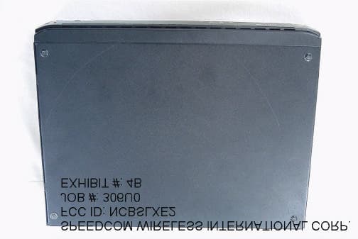
Click to zoom
Application Details
- Equipment Class
- DSS - Part 15 Spread Spectrum Transmitter
- Date of Grant
- Apr 11, 2002
- Application Purpose
- Original Equipment
- Date of Application
- Apr 11, 2002
- Equipment Note
- Spread Spectrum Transmitter
- Frequency Range
- 2421.10000000 - 2422.10000000
- Company
- Wave Wireless Networking
- Country
- United States
Documents & Files
Document Text
Text extracted from the exhibit documents filed with the FCC. Open a document above to read the original.
Users Manual
SPEEDLAN 4100 & 4200 Installation and Operation User Guide -1 Version 1.0 / Last Revised August, 2000 Wave Wireless Networking a SPEEDCOM Wireless Company 1748 Independence Blvd. C-5 Sarasota, FL 34234 941-358-9283 www.speedlan.com SPEEDLAN Shelf Mount Manual Product ID NCBSLXE2 Installation and Operation User Guide Version 1.1 / Last Revised July 15, 2001 Wave Wireless Networking a SPEEDCOM Wireless Company 1748 Independence Blvd., C-5 Sarasota, FL 34234 941-358-9283 www.wavewireless.com SPEEDLAN 4100 & 4200 Installation and Operation User Guide -2 Copyright/Liability SPEEDLAN Shelf Mount Manual. Copyright ©2000.Wave Wireless Networking, a SPEEDCOM Wireless Company. All rights reserved. No part of this publication may be reproduced, transmitted, transcribed, stored in a retrieval system, or translated into any language in any form by any means without the written permission Wave Wireless, a SPEEDCOM Wire- less Company. Wave Wireless Networking, a SPEEDCOM Wireless Company, shall not be liable for errors contained herein or for inci- dental or consequential damages in connection with the furnishing, performance, or use of this material. Wave Wireless Networking, a SPEEDCOM Wireless Company, reserves the right to revise this publication from time to time and make changes in content without obligation to notify any person of such revision changes. Contents of this publication may be preliminary and/or may be changed at any time without notice and shall not be regarded as a warranty. Trademarks Wave Wireless Networking's name and all trademarks in this document are property of SPEEDCOM Wireless, except for Microsoft® Corporation Windows 95®, Windows 98®, and Windows NT®. SPEEDLAN Installation and Operation User Guide Contents-1 Chapter 1 - Introduction .................................................................................. 1-1 Features and Benefits .................................................................................................................1-2 Transparent Ethernet Bridging with Advanced Filtering for Security and Network Reliability ........1-2 IP Routing with Advanced Filtering for Security.......................................................................1-3 SNMP Management............................................................................................................1-3 Wireless Multipoint Protocol ................................................................................................1-3 ISP Functionality .................................................................................................................1-3 Features ...................................................................................................................................1-4 SNMP Features...................................................................................................................1-4 ISP Features .......................................................................................................................1-4 SNMP Management............................................................................................................1-4 IP-Router Features ..............................................................................................................1-5 Encryption Features (Add-on Option)....................................................................................1-5 Chapter 2 - Quick Start .................................................................................... 2-1 System Description .....................................................................................................................2-2 Rooftop and Tower Installations Warning ..............................................................................2-2 Package Contents ......................................................................................................................2-2 Installation Steps ........................................................................................................................2-3 Installation Diagram ...................................................................................................................2-7 Polarizations on a Grid Antenna .................................................................................................2-8 Vertical Polarity & Horizontal Polarity ....................................................................................2-8 Chapter 3 - Hardware ....................................................................................... 3-1 Drawings of Components ...........................................................................................................3-2 SPEEDLAN Front Panel.......................................................................................................3-3 SPEEDLAN Back Panel ........................................................................................................3-3 Restoring Factory Default Settings on the SPEEDLAN ....................................................................3-4 Updating the Firmware ...............................................................................................................3-5 Chapter 4 - Overview of Configurator ............................................................ 4-1 Installation and Setup .................................................................................................................4-2 Windows 95/98/NT 4.0 SPEEDLAN Configurator .................................................................4-2 Toolbar and Menus ....................................................................................................................4-2 File Menu ..........................................................................................................................4-2 Configuring a SPEEDLAN Brouter .................................................................................4-2 Configuring a Saved…
Text truncated - open the document above for the full version.
Users Manual
SPEEDLAN Installation and Operation User Guide 11-2SNMP Monitoring To monitor the SNMP results, choose the appropriate selection by choosing Monitor (on the SPEEDLAN Configurator)+ Advanced + your selection. Remote Statistics In the Remote Statistics dialog box, you are presented with information regarding the way a brouter handles packets as they are passing through an interface. Below you will find many useful items for diagnosing and gathering traffic statistics for each interface. TIP SPEEDLAN Installation and Operation User Guide SNMP Monitoring11-3 •Unicast packets in The number of subnetwork-unicast packets delivered to a higher-layer protocol. •Unicast packets out The total number of octets (bytes) transmitted out of the interface, including framing characters. •Non-Unicast packets in The number of non-unicast (i.e., subnetwork-broadcast or subnetwork-multicast) packets delivered to a higher-layer protocol. •Non-Unicast packets out The total number of octets (bytes) transmitted out of the interface, including framing characters. •Bytes in Total number of octets (bytes) received on the interface, including framing characters. •Bytes out The total number of packets that have higher-layer protocols requested be transmitted to a non-unicast (i.e., a subnetwork-broadcast or subnetwork-multicast) address, including those that were discarded or not sent. •Bridge in discards The count of valid frames that have been received which were discarded (i.e., filtered) by the forwarding process. •Bridge out packets The number of frames that have been transmitted by this port to its segment. Note that a frame transmitted on the interface corresponding to this port is not counted by this object unless it is for a protocol being processed by the local bridging function. •In errors The number of inbound packets that contained errors preventing them from being deliverable to a higher-layer protocol. •In discards The number of inbound packets which were chosen to be discarded even though they were deliverable. One possible reason for discarding such a packet could be to free up buffer space. •In Alignment Errors A count of frames received on a particular interface that are not an integral number of octets in length and do not pass the FCS check. •In FCS Errors A count of frames received on a particular interface that are an integral number of octets in length, but do not pass the FCS check. SPEEDLAN Installation and Operation User Guide 11-4SNMP Monitoring •Out Errors The number of outbound packets that could not be transmitted because of errors. •Out Carrier Sense Errors The number of times that the carrier-sense condition was lost or never asserted when the SPEEDLAN attempted to transmit a frame on a particular interface. •Out Collisions A count of successfully transmitted frames on a particular interface for which transmission is inhibited by exactly one or more collisions, plus the number of times that a collision is detected on a particular interface later than 512 bit-times into the transmission of a packet. SPEEDLAN Installation and Operation User Guide SNMP Monitoring11-5 Interface Monitor The interfaces table contains information on the brouter's interface(s). Each interface is thought of as being attached to a `subnetwork'. Note that this term should not be confused with `subnet' which refers to an address-partitioning scheme used in the Internet suite of protocols. •Ty p e The type of interface, distinguished according to the physical-link protocols immediately below the network layer in the protocol stack. The possible types are: other, regular1822, hdh1822, ddn-x25, rfc877-x25, ethernet-csmacd, iso88023-csmacd, iso80024-tokenbus, iso88025-tokenring, iso99026-man, starLan, proteon-10Mbit, proteon-80Mbit, hyperchannel, fddi, lapb, sdlc, ds1, e1, basicISDN, PrimaryISDN, propPointToPointSerial, ppp, softwareloopback, eon, ethernet-3Mbit, nsip, slip, ultra, ds3, sip, frame-relay. SPEEDLAN Installation and Operation User Guide 11-6SNMP Monitoring •Description A textual string containing information about the interface. This string should include the name of the manufacturer, the product name, and the version of the hardware interface. •MIB specific definator A reference to MIB definitions specific to the particular media being used to realize the interface. For example, if the interface is being realized by an Ethernet, then the value of this object refers to a document defining objects specific to the Ethernet. If this information is not present, its value will be set to 0. •Physical Address The interface's address at the protocol layer immediately below the network layer in the protocol stack. For interfaces which do not have such an address (e.g., a serial line), this object should contain an octet string of zero length. •Last Change The value of sysUpTime at the time the interface entered its current operational state. If the current state was entered prior to the last reinitialization of the local network-management subsystem, then this object contains a value of zero. •Operational Status The state of the interface. The testing state indicates that no operational packets can be passed. Up - ready to pass packets; Down - cannot pass packets; testing - in some test mode. •Admin Status The desired state of the interface. The testing state indicates that no operational packets can be passed. •Speed An estimate of the interface's current bandwidth in bits per second. For interfaces which do not vary in bandwidth or whose bandwidth can't be accurately estimated, this object should contain the nominal bandwidth. •Max packet size The size of the largest datagram which can be sent/received on the interface, specified in octets. For interfaces used for transmitting network datagrams, this is the size of the largest network datagram that can be sent on the interface. •In octets (bytes) The total number of octets (bytes) received on the interface, including framing characters. •In unicast packets The …
Text truncated - open the document above for the full version.
Block Diagram
WaveLan Transmitter WL Turbo 11 Mb PC Card ISA Bus PCI Bus Switching Power Supply 60 W +5 Vdc, +12 Vdc -5 Vdc, -12 Vdc Motherboard WinNET-5BLIP (with Ethernet NIC Card) IDE Bus Flash ROM Module 115/230 Vac To Antena Block Diagram of Wireless Ethernet Bridge NCBSLXE2 To Ethernet
Cover Letter(s)
February 7, 2002 Federal Communications Commission Authorization and Evaluation Division 7435 Oakland Mills Road Columbia, MD 21046 RE: Confidentiality Request regarding application for certification of SPEEDCOM Wireless FCC Certification of FCC ID: NCBSLXE2 To Whom It May Concern: Pursuant to Sections 0.457 and 0.459 of the Commission’s Rules, we hereby request confidential treatment of information accompanying this application as outlined below: Schematics for the radio and amplifier The above materials contain trade secrets and proprietary information not customarily released to the public. The public disclosure of these materials may be harmful to the applicant and provide unjustified benefits to its competitors. The applicant understands that pursuant to Section 0.457 of the Rules, disclosure of this application and all accompanying documentation will not be made before the date of the Grant for this application. Sincerely, Janusz Dyndul Product Certification Manager SPEEDCOM Wireless Corporation 941-358-9283 ext. 407 [email protected]
External Photos
WAVE WIRELESS NETWORKING DIV. OF SPEEDCOM WIRELESS CORP. FCC ID: NCBSLXE2 EXHIBIT #: 4 WAVE WIRELESS NETWORKING DIV. OF SPEEDCOM WIRELESS CORP. FCC ID: NCBSLXE2 EXHIBIT #: 4
ID Label/Location Info
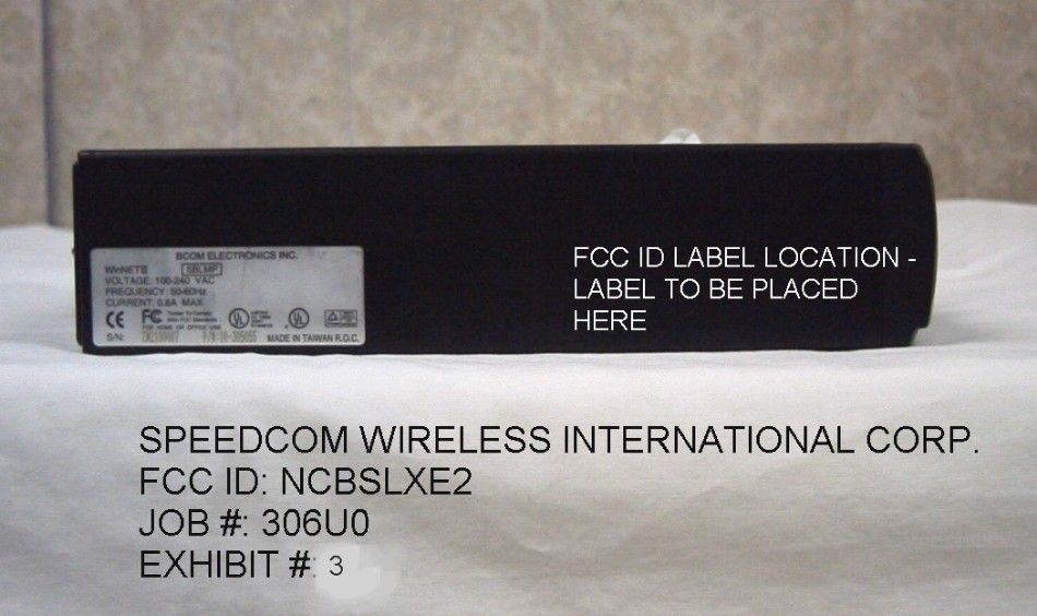
SPEEDLAN FCC ID: NCBSLXE2 This device complies with Part 15 of the FCC Rules. Operation is subject to the following two conditions: 1) This device may not cause harmful interference, and 2) This device must accept any interference received, including interference that may cause undesired operation. This is the FCC ID Label sample. It should be placed on the side of the unit. SPEEDCOM WIRELESS INTERNATIONAL CORP. FCC ID: NCBSLXE2 JOB #: 306U0 EXHIBIT #: 2
Internal Photos
COMPONENT VIEW INTERNAL PHOTOS WAVE WIRELESS NETWORKING DIV. OF SPEEDCOM WIRELESS CORP. FCC ID: NCBSLXE2 EXHIBIT #: 5 INTERNAL COMPONENT VIEW - AMPLIFIER WAVE WIRELESS NETWORKING DIV. OF SPEEDCOM WIRELESS CORP. FCC ID: NCBSLXE2 EXHIBIT #: 5 INTERNAL SOLDER VIEW PHOTOS WAVE WIRELESS NETWORKING DIV. OF SPEEDCOM WIRELESS CORP. FCC ID: NCBSLXE2 EXHIBIT #: 5 INTERNAL SOLDER VIEW AMPLIFIER WAVE WIRELESS NETWORKING DIV. OF SPEEDCOM WIRELESS CORP. FCC ID: NCBSLXE2 EXHIBIT #: 5
Operational Description
Operational description. Product overview This product is a Ethernet (10/100base T) to RF transceiver. The product consists of a custom IBM compatible computer with a network interface controller card(NIC) and a Agere ORINOCO radio transceiver installed in a PCMIA port card. The RF card: The unit uses multiple chipping codes and other special processes to achieve its high-speed rate. 1 Mb/s uses DBPSK, 2 Mb/s uses DQPSK, 5.5 Mb/s and 11Mb/s uses complementary code keying (CCK). The oscillators employed are a VCO from 2060 to 2100MHz controlled by software, 704 MHz, and which when divided by 2 gives the 352 MHz an IF local oscillator. The computer: The CPU uses a 33MHz oscillator.
Test Report
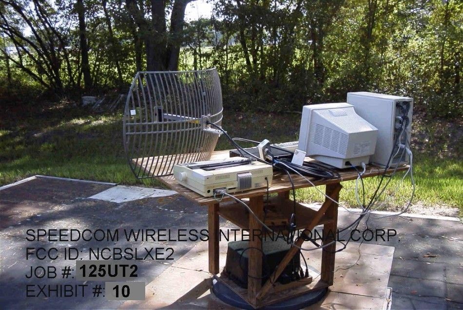
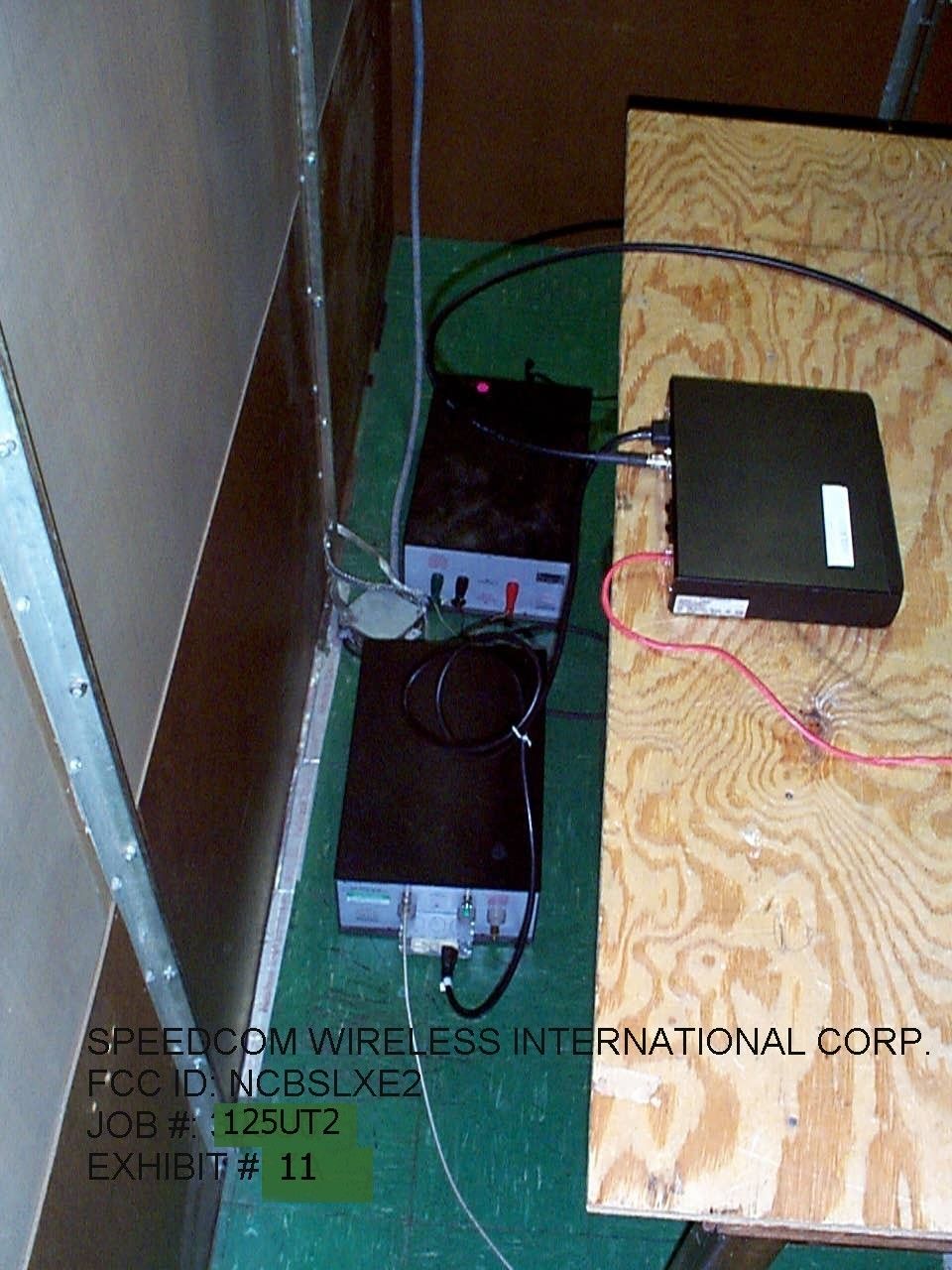
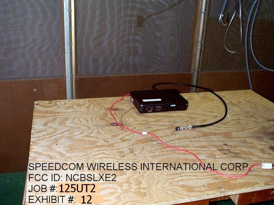
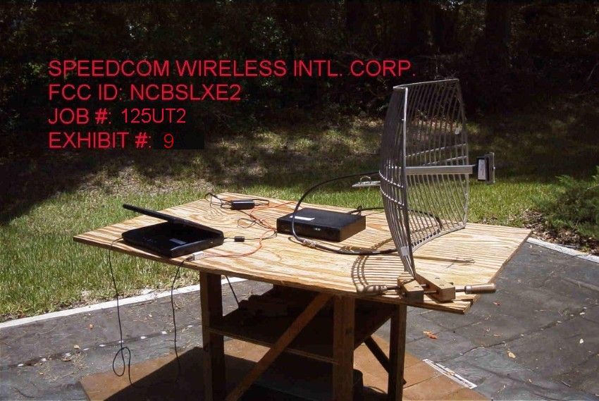
APPLICANT: WAVE WIRELESS NETWORKING FCC ID: NCBSLXE2 REPORT #: T:\W\Wave_NCB\125UT2\125UT2TestReport.doc TABLE OF CONTENTS LIST APPLICANT: WAVE WIRELESS NETWORKING FCC ID: NCBSLXE2 TABLE OF CONTENTS TEST REPORT CONTAINING: PAGE 1.............LETTER OF EXPLANATION PAGE 2-5...........LIST OF TEST EQUIPMENT PAGE 6.............TEST PROCEDURES PAGE 7.............PRODUCT DESCRIPTION PAGE 8.............POWERLINE CONDUCTED INTERFERENCE PAGE 9-10..........POWERLINE CONDUCTED PLOTS PAGE 11.............OCCUPIED BANDWIDTH AND PLOT PAGE 12.............POWER OUTPUT PAGE 13.............METHOD OF MEASURING RF CONDUCTED AND SPURIOUS EMISSIONS AT ANTENNA TERMINALS DATA PAGE 14-16..........RADIATION INTERFERENCE TEST DATA PAGE 17.............METHOD OF MEASURING RADIATED SPURIOUS EMISS. PAGE 18.............RADIATED SPURIOUS EMISSIONS INTO ADJACENT RESTRICTED BANDS PAGE 19.............POWER SPECTRAL DENSITY PAGE 20.............POWER SEPCTRAL DENSITY PLOT EXHIBIT ATTACHMENTS: EXHIBIT 1...........REQUEST FOR CONFIDENTIALITY LETTER EXHIBIT 2...........FCC ID LABEL SAMPLE EXHIBIT 3...........SKETCH OF FCC ID LABEL LOCATION EXHIBIT 4...........EXTERNAL PHOTOS EXHIBIT 5...........INTERNAL PHOTOS EXHIBIT 6...........BLOCK DIAGRAM EXHIBIT 7...........SCHEMATICS - AMPLIFIER EXHIBIT 8...........SCHEMATICS – LUCENT RADIO EXHIBIT 9-10........TEST SET UP PHOTOS– RADIATED EXHIBIT 11-12.......TEST SET UP PHOTOS – POWERLINE CONDUCTED EXHIBIT 13..........OPERATIONAL DESCRIPTION EXHIBIT 14..........PROCESSING GAIN INFORMATION EXHIBIT 15..........INSTRUCTION MANUAL APPLICANT: WAVE WIRELESS NETWORKING FCC ID: NCBSLXE2 REPORT #: T:\W\Wave_NCB\125UT2\125UT2TestReport.doc Page 1 of 20 March 15, 2002 Federal Communications Commission Authorization and Evaluation Division 7435 Oakland Mills Road Columbia, MD 21046 SUBJECT: WAVE WIRELESS NETWORKING DIVISION OF SPEEDCOM WIRELESS CORP. FCC ID: NCBSLXE2 To Whom It May Concern: The attached application is for a direct sequence spread spectrum Assembly, made up of the Bridge/Radio, 50 foot of coax, a lightning arrestor, amplifier, and a parabolic antenna. This system has only one type of antenna, a parabolic dish that has 24 dBi. WAVE WIRELESS NETWORKING purchases standard antennas from the manufacturer. The antenna is intended to be used outside and mounted on fixed, permanent structures. The NCBSLXE2 uses unique connectors (reverse TNC). This unit is designed to be professionally installed. Should you have any questions or require any further information with regards to this, please feel free to contact me. Sincerely, Mario R. de Aranzeta Engineer MRD/sh Encl. APPLICANT: WAVE WIRELESS NETWORKING FCC ID: NCBSLXE2 REPORT #: T:\W\Wave_NCB\125UT2\125UT2TestReport.doc Page 2 of 20 Equipment List DEVICE MFGR MODEL SERNO CAL/CHAR DATE DUE DATE or STATUS X 3-Meter OATS TEI N/A N/A Listed 12/22/99 12/22/02 3/10-Meter OATS TEI N/A N/A Listed 3/26/01 3/26/04 X Receiver, Beige Tower X Spectrum Analyzer (Tan) HP 8566B Opt 462 3138A07786 3144A20661 CAL 8/31/01 8/31/02 X RF Preselector (Tan) HP 85685A 3221A01400 CAL 8/31/01 8/31/02 X Quasi-Peak Adapter (Tan) HP 85650A 3303A01690 CAL 8/31/01 8/31/02 Receiver, Blue Tower Spectrum Analyzer (Blue) HP 8568B 2928A04729 2848A18049 CHAR 10/22/01 10/22/02 RF Preselector (Blue) HP 85685A 2926A00983 CHAR 10/22/01 10/22/02 Quasi-Peak Adapter (Blue) HP 85650A 2811A01279 CHAR 10/22/01 10/22/02 Biconnical Antenna Electro-Metrics BIA-25 1171 CAL 4/26/01 4/26/03 X Biconnical Antenna Eaton 94455-1 1096 CAL 10/1/01 10/1/02 Biconnical Antenna Eaton 94455-1 1057 CHAR 3/15/00 3/15/01 BiconiLog Antenna EMCO 3143 9409-1043 Log-Periodic Antenna Electro-Metrics LPA-25 1122 CAL 10/2/01 10/2/02 X Log-Periodic Antenna Electro-Metrics EM-6950 632 CHAR 10/15/01 10/15/02 Log-Periodic Antenna Electro-Metrics LPA-30 409 CHAR 10/16/01 10/16/02 Dipole Antenna Kit Electro-Metrics TDA-30/1-4 152 CAL 3/21/01 3/21/02 Dipole Antenna Kit Electro-Metrics TDA-30/1-4 153 CHAR 11/24/00 11/24/01 X Double-Ridged Horn Antenna Electro-Metrics RGA-180 2319 CAL 12/19/01 12/19/02 Horn Antenna Electro-Metrics EM-6961 6246 CAL 3/21/01 3/21/02 APPLICANT: WAVE WIRELESS NETWORKING FCC ID: NCBSLXE2 REPORT #: T:\W\Wave_NCB\125UT2\125UT2TestReport.doc Page 3 of 20 DEVICE MFGR MODEL SERNO CAL/CHAR DATE DUE DATE or STATUS Horn Antenna ATM 19-443-6R None No Cal Required Passive Loop Antenna EMC Test Systems EMCO 6512 9706-1211 CHAR 7/10/01 7/10/02 X Line Impedance Stabilization . . . Electro-Metrics ANS-25/2 2604 CAL 10/9/01 10/9/02 Line Impedance Stabilization . . . Electro-Metrics EM-7820 2682 CAL 3/16/01 3/16/02 Termaline Wattmeter Bird Electronic Corporation 611 16405 CAL 5/25/99 (5/25/00) Termaline Wattmeter Bird Electronic Corporation 6104 1926 CAL 12/12/01 12/12/02 Oscilloscope Tektronix 2230 300572 CHAR 2/1/01 2/1/02 Temperature Chamber Tenney Engineering TTRC 11717-7 CHAR 1/22/02 1/22/03 AC Voltmeter HP 400FL 2213A14499 CAL 10/9/01 10/9/02 AC Voltmeter HP 400FL 2213A14261 CHAR 10/15/01 10/15/02 AC Voltmeter HP 400FL 2213A14728 CHAR 10/15/01 10/15/02 X Digital Multimeter Fluke 77 35053830 CHAR 1/8/02 1/8/03 Digital Multimeter Fluke 77 43850817 CHAR 1/8/02 1/8/03 Digital Multimeter HP E2377A 2927J05849 CHAR 1/8/02 1/8/03 Multimeter Fluke FLUKE-77-3 79510405 CAL 9/26/01 9/26/02 X Peak Power Meter HP 8900C 2131A00545 CHAR 1/26/01 1/26/02 Digital Thermometer Fluke 2166A 42032 CAL 1/16/02 1/16/03 Thermometer Traulsen SK-128 CHAR 1/22/02 1/22/03 Temp/Humidity gauge EXTech 44577F E000901 CHAR 1/22/02 1/22/03 Frequency Counter HP 5352B 2632A00165 CAL 11/28/01 11/28/02 Power Sensor Agilent Technologies 84811A 2551A02705 CAL 1/26/01 1/26/02 Injection Probe Fischer Custom Communications F-120-9A 270 CAL 6/1/01 6/1/02 Service Monitor IFR FM/AM 500A 5182 CAL 11/22/00 11/22/01 Comm. Serv. Monitor IFR FM/AM 1200S 6593 CAL 11/12/99 11/12/00 APPLICANT: WAVE WIRELESS NETWORKING FCC ID: NCBSLXE2 REPORT #: T:\W\Wave_NCB\125UT2\125UT2TestReport.doc Page 4 of 20 DEVICE MFGR MODEL SERNO CAL/CHAR DATE DUE DATE or STATUS Signal Ge…
Text truncated - open the document above for the full version.
Test Report
Measurement file output name is: 5mbit.cnd Input command file name is: INPUT.CMD Note: 5.5 Mbit, 6 dB SIR tested for ( 15 dB SNR - 10.4 + 1 impl. losses). Input CW correction level: 6 dB Takes into account 1 dB of implementation loss (allowed 2 dB). Lowcount is: 1000 messages Only RxD errors are taken into account since these need better SIR then preamble at 1 MBit Highcount is: 50000 messages Attention: Input the red cells for correct spreadsheet calculations! total errors 45 out of 280 measurement points. Rx level DUT is: -53 dBm percentage 16.07% Number of received data errors as a function of frequency and interference level OK? =<20%, OK Not measured combinations listed as "-1" HIJKLMN O PQ RS Uncorrected Interference level dialed at CW generator -60 -59 -58 -57 -56 -55 -54 -53 -52 RxD Errors PDA RxD Errors PDA Both error True CW interference level at receiver input (dBm) detected missing detected missing RxD and -66 -65 -64 -63 -62 -61 -60 -59 -58 full test full test up to CW AT CW PDA J/S ratio (dB) -13 #PDA -12 #PDA -11 #PDA -10 #PDA -9 #PDA -8 #PDA -7 #PDA -6 #PDA -5 #PDA range range =< -59 dBm = -59 dBm =< -59 dBm Frequency (Hz) (J/S = -5-1 dB) (J/S = -5-1 dB) time date 2409000000 0 1000 0 1000 0 1000 0 1000 0 1000 0 1000 0 1000 0 1000 0 50000 OK, 0 RxD error s OK, No PDA err o 000 15:53:49 4/15/99 2409050000 0 1000 0 1000 0 1000 0 1000 0 1000 0 1000 0 1000 0 1000 0 50000 OK, 0 RxD error s OK, No PDA err o 000 15:52:18 4/15/99 2409100000 0 1000 0 1000 0 1000 0 1000 0 1000 0 1000 0 1000 0 1000 0 50000 OK, 0 RxD error s OK, No PDA err o 000 15:50:48 4/15/99 2409150000 0 1000 0 1000 0 1000 0 1000 0 1000 0 1000 0 1000 0 1000 0 50000 OK, 0 RxD error s OK, No PDA err o 000 15:49:19 4/15/99 2409200000 0 1000 0 1000 0 1000 0 1000 0 1000 0 1000 0 1000 0 1000 0 50000 OK, 0 RxD error s OK, No PDA err o 000 15:47:48 4/15/99 2409250000 0 1000 0 1000 0 1000 0 1000 0 1000 0 1000 0 1000 0 1000 0 50000 OK, 0 RxD error s OK, No PDA err o 000 15:46:19 4/15/99 2409300000 0 1000 0 1000 0 1000 0 1000 0 1000 0 1000 0 1000 0 1000 0 50000 OK, 0 RxD error s OK, No PDA err o 000 15:44:49 4/15/99 2409350000 0 1000 0 1000 0 1000 0 1000 0 1000 0 1000 0 1000 0 1000 0 50000 OK, 0 RxD error s OK, No PDA err o 000 15:43:18 4/15/99 2409400000 0 1000 0 1000 0 1000 0 1000 0 1000 0 1000 0 1000 0 1000 0 50000 OK, 0 RxD error s OK, No PDA err o 000 15:41:49 4/15/99 2409450000 0 1000 0 1000 0 1000 0 1000 0 1000 0 1000 0 1000 0 1000 0 50000 OK, 0 RxD error s OK, No PDA err o 000 15:40:18 4/15/99 2409500000 0 1000 0 1000 0 1000 0 1000 0 1000 0 1000 0 1000 0 1000 0 50000 OK, 0 RxD error s OK, No PDA err o 000 15:38:48 4/15/99 2409550000 0 1000 0 1000 0 1000 0 1000 0 1000 0 1000 0 1000 0 1000 0 50000 OK, 0 RxD error s OK, No PDA err o 000 15:37:18 4/15/99 2409600000 0 1000 0 1000 0 1000 0 1000 0 1000 0 1000 0 1000 0 1000 0 50000 OK, 0 RxD error s OK, No PDA err o 000 15:35:48 4/15/99 2409650000 0 1000 0 1000 0 1000 0 1000 0 1000 0 1000 0 1000 0 1000 0 50000 OK, 0 RxD error s OK, No PDA err o 000 15:34:18 4/15/99 2409700000 0 1000 0 1000 0 1000 0 1000 0 1000 0 1000 0 1000 0 1000 0 50000 OK, 0 RxD error s OK, No PDA err o 000 15:32:48 4/15/99 2409750000 0 1000 0 1000 0 1000 0 1000 0 1000 0 1000 0 1000 0 1000 0 50000 OK, 0 RxD error s OK, No PDA err o 000 15:31:17 4/15/99 2409800000 0 1000 0 1000 0 1000 0 1000 0 1000 0 1000 0 1000 0 1000 0 50000 OK, 0 RxD error s OK, No PDA err o 000 15:29:47 4/15/99 2409850000 0 1000 0 1000 0 1000 0 1000 0 1000 0 1000 0 1000 0 1000 0 50000 OK, 0 RxD error s OK, No PDA err o 000 15:28:17 4/15/99 2409900000 0 1000 0 1000 0 1000 0 1000 0 1000 0 1000 0 1000 0 1000 0 50000 OK, 0 RxD error s OK, No PDA err o 000 15:26:46 4/15/99 2409950000 0 1000 0 1000 0 1000 0 1000 0 1000 0 1000 0 1000 0 1000 0 50000 OK, 0 RxD error s OK, No PDA err o 000 15:25:16 4/15/99 2410000000 0 1000 0 1000 0 1000 0 1000 0 1000 0 1000 0 1000 0 1000 0 50000 OK, 0 RxD error s OK, No PDA err o 000 15:23:45 4/15/99 2410050000 0 1000 0 1000 0 1000 0 1000 0 1000 0 1000 0 1000 0 1000 0 50000 OK, 0 RxD error s OK, No PDA err o 000 15:22:15 4/15/99 2410100000 0 1000 0 1000 0 1000 0 1000 0 1000 0 1000 0 1000 0 1000 0 50000 OK, 0 RxD error s OK, No PDA err o 000 15:20:45 4/15/99 2410150000 0 1000 0 1000 0 1000 0 1000 0 1000 0 1000 0 1000 0 1000 0 50000 OK, 0 RxD error s OK, No PDA err o 000 15:19:14 4/15/99 2410200000 0 1000 0 1000 0 1000 0 1000 0 1000 0 1000 0 1000 0 1000 0 50000 OK, 0 RxD error s OK, No PDA err o 000 15:17:44 4/15/99 2410250000 0 1000 0 1000 0 1000 0 1000 0 1000 0 1000 0 1000 0 1000 0 50000 OK, 0 RxD error s OK, No PDA err o 000 15:16:14 4/15/99 2410300000 0 1000 0 1000 0 1000 0 1000 0 1000 0 1000 0 1000 0 1000 0 50000 OK, 0 RxD error s OK, No PDA err o 000 15:14:43 4/15/99 2410350000 0 1000 0 1000 0 1000 0 1000 0 1000 0 1000 0 1000 0 1000 0 50000 OK, 0 RxD error s OK, No PDA err o 000 15:13:13 4/15/99 2410400000 0 1000 0 1000 0 1000 0 1000 0 1000 0 1000 0 1000 0 1000 0 50000 OK, 0 RxD error s OK, No PDA err o 000 15:11:42 4/15/99 2410450000 0 1000 0 1000 0 1000 0 1000 0 1000 0 1000 0 1000 0 1000 0 50000 OK, 0 RxD error s OK, No PDA err o 000 15:10:12 4/15/99 2410500000 0 1000 0 1000 0 1000 0 1000 0 1000 0 1000 0 1000 0 1000 0 50000 OK, 0 RxD error s OK, No PDA err o 000 15:08:42 4/15/99 2410550000 0 1000 0 1000 0 1000 0 1000 0 1000 0 1000 0 1000 0 1000 0 50000 OK, 0 RxD error s OK, No PDA err o 000 15:07:12 4/15/99 2410600000 0 1000 0 1000 0 1000 0 1000 0 1000 0 1000 0 1000 0 1000 0 50000 OK, 0 RxD error s OK, No PDA err o 000 15:05:42 4/15/99 2410650000 0 1000 0 1000 0 1000 0 1000 0 1000 0 1000 0 1000 0 1000 0 50000 OK, 0 RxD error s OK, No PDA err o 000 15:04:12 4/15/99 2410700000 0 1000 0 1000 0 1000 0 1000 0 1000 0 1000 0 1000 0 1000 0 50000 OK, 0 RxD error s OK, No PDA err o 000 15:02:42 4/15/99 2410750000 0 1000 0 1000 0 1000 0 1000 0 1000 0 1000 0 1000 0 1000 0 50000 OK, 0 RxD error s OK, No PDA err o 000 15:01:11 4/15/99 2410800000 0 1000 0 1000 0 1000 0 1000 0 1000 0 1000 0 1000 0 1000 0 50000 OK, 0 RxD …
Text truncated - open the document above for the full version.
Test Report
Nederland B.V. WCND FCC ID: WLPC24H/WLPCE24H Report No. 011734, Rev. B TEST REPORT Subject: Processing Gain For WaveLAN IEEE PC CARD type 2 HS Ref.: FCC Rules 47 CFR Part 15, Section 5.247d Report Prepared by: Maarten Visee May 6, 1999 Name Signature Date Concurrence: 1. Director of Engineering Bruce Tuch May 6, 1999 Name Signature Date 2. Team Captain Frans Hoekstra May 6, 1999 Name Signature Date FCC Processing Gain Measurements Results, FCCID WLPC24H/WLPCE24H, Report No. 011734, Rev. B. Lucent WCND Confidential ©1999 2 Lucent WCND Confidential Information ©1999 FCC Processing Gain Measurements Results, FCCID WLPC24H/WLPCE24H, Report No. 011734, Rev. B. Lucent WCND Confidential ©1999 i Date Section Description 04/16/99, Rev. A Initial release. 05/6/99, Rev. B 2 Changed spreading gain into processing gain. 4.1 For data rates of 5.5 and 11 Mbit/s changed processing gain requirements of 9 dB into 10 dB. 4.2 Changed description for demodulated data availability at the interconnection between RF and DSP into the interconnection between DSP and digital circuits. Changed spreading gain into processing gain. 7.2, 7.3 Changed sub sections Measurement Results and Measurement Conclusion. Annex A Updated flow chart. Change History: FCC Processing Gain Measurements Results, FCCID WLPC24H/WLPCE24H, Report No. 011734, Rev. B. Lucent WCND Confidential ©1999 1 This document describes the Receiver Processing Gain verification measurements performed at the WaveLAN-II PC-Card Type 2, according to Ref.[2]. The Lucent WaveLAN-II PC-Card Type 2 product confirms to the minimum required 10 dB processing gain, as set forth by the FCC for operation in the 2.4 GHz ISM band. 1- Document FCC 97-114, Appendix C, Guidance on Measurements for Direct Sequence Spread Spectrum Systems. 2- Hardware Functional Specification for WaveLAN-II Embedded, High Speed, Doc. No. 011735, Rev. A, Source Organization Lucent Technologies WCND Utrecht. 3- Viterbi, A. J., Principles of Coherent Communications, New York, McGraw-Hill 1966. 4- Proakis, J.G., Digital Communications, New York, McGraw-Hill 1989, page 270. 4.1 Test introduction - FCC requirements: Part of FCC certification for the Lucent WaveLAN IEEE 802.11 High Speed compliant Network Interface Card (NIC) is a processing gain test. This test proves that the receiver of the tested product employs a true spread spectrum device receiver structure, taking full advantage of the direct sequence spread spectrum modulation technique. This test verifies the receiver processing gain to be 10 dB or more for a data rate of 1, 2, 5.5 and 11 Mbit/s, by monitoring the Bit Error Rate (BER) of the product under test for each data rate, while operating under strict defined received signal conditions. Several methods of showing compliance to the rules are possible, from a stepped CW jammer to a continuous sweeping CW in…
Text truncated - open the document above for the full version.
Contact Information
Applicant
John Dyndul(Product Certification Manager)
Test Firm
Timco Engineering, Inc.S Sanders
Technical Specifications
| # | Rule Parts | Frequency Range | Power Output |
|---|---|---|---|
| 1 | 15C | 2.42 GHz - 2.42 GHz | 125.00 mW |
Other Applications from Wave Wireless Networking
NCBSL9101A
Dec 11, 2003Spread Spectrum Transmitter
Equipment Class
DTS - Digital Transmission System
NCBSL9102A
Dec 09, 2003SPREAD SPECTRUM TRANSMITTER
Equipment Class
DTS - Digital Transmission System
NCBSL9102
May 08, 2002Spread Spectrum Transmitter
Equipment Class
DTS - Digital Transmission System
NCBSL9101
May 06, 2002Spread Spectrum Transmitter
Equipment Class
DTS - Digital Transmission System
NCBSL8500
Mar 31, 2002Spread Spectrum Transmitter
Equipment Class
DSS - Part 15 Spread Spectrum Transmitter