NCBSLTMAWireless LAN
Wave Wireless Networking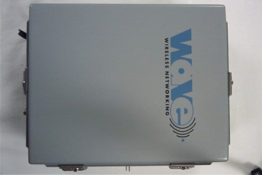
Click to zoom
Application Details
- Equipment Class
- DSS - Part 15 Spread Spectrum Transmitter
- Date of Grant
- Nov 01, 2001
- Application Purpose
- Original Equipment
- Date of Application
- Nov 01, 2001
- Equipment Note
- Wireless LAN
- Frequency Range
- 2433.00000000 - 2433.00000000
- Company
- Wave Wireless Networking
- Country
- United States
Documents & Files
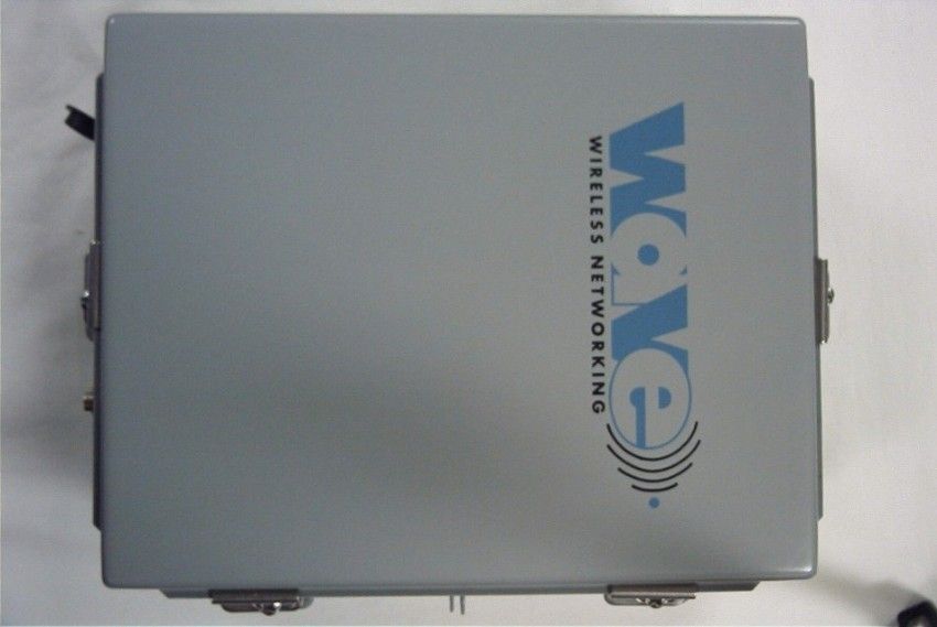
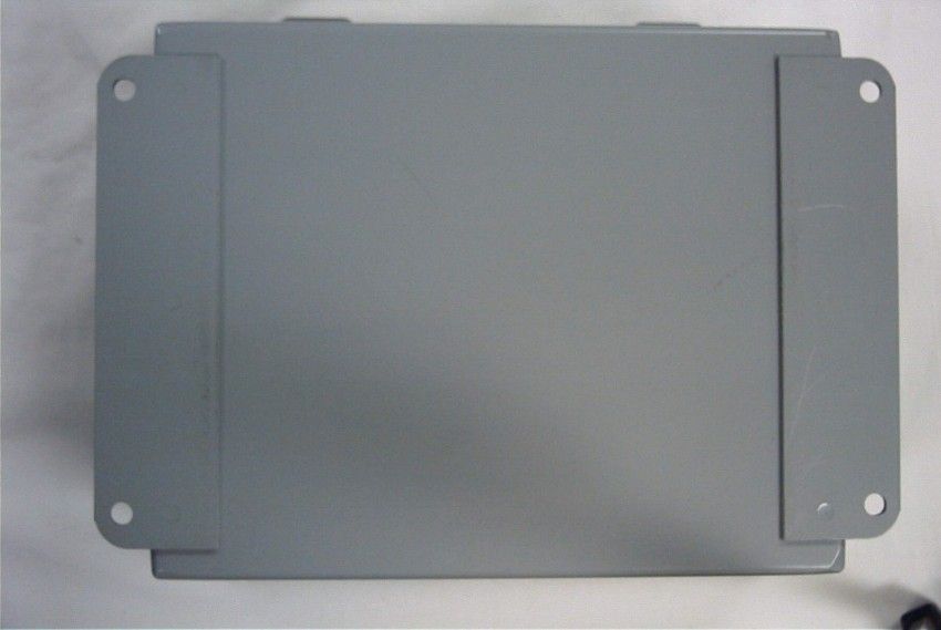
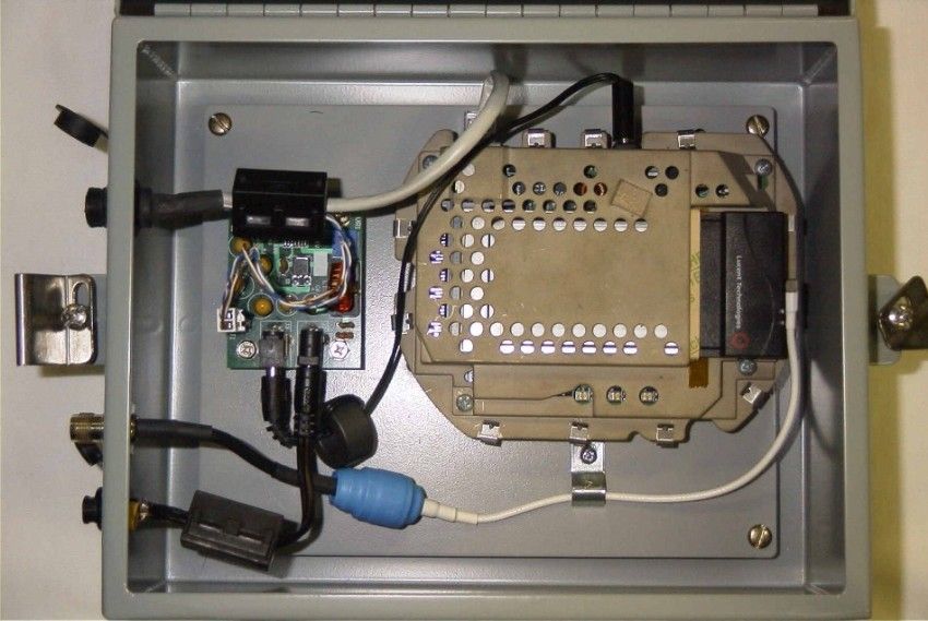
Document Text
Text extracted from the exhibit documents filed with the FCC. Open a document above to read the original.
Users Manual
SPEEDLAN 4100 & 4200 Installation and Operation User Guide -1 Version 1.0 / Last Revised August, 2000 Wave Wireless Networking a SPEEDCOM Wireless Company 1748 Independence Blvd. C-5 Sarasota, FL 34234 941-358-9283 www.speedlan.com SPEEDLAN 4100 & 4200 Installation and Operation User Guide Version 1.0 / Last Revised September, 2000 Wave Wireless Networking a SPEEDCOM Wireless Company 1748 Independence Blvd., C-5 Sarasota, FL 34234 941-358-9283 www.speedlan.com SPEEDLAN 4100 & 4200 Installation and Operation User Guide -2 Copyright/Liability SPEEDLAN 4100 & 4200. Copyright ©2000.Wave Wireless Networking, a SPEEDCOM Wireless Company. All rights reserved. No part of this publication may be reproduced, transmitted, transcribed, stored in a retrieval system, or trans- lated into any language in any form by any means without the written permission Wave Wireless, a SPEEDCOM Wireless Company. Wave Wireless Networking, a SPEEDCOM Wireless Company, shall not be liable for errors contained herein or for inci- dental or consequential damages in connection with the furnishing, performance, or use of this material. Wave Wireless Networking, a SPEEDCOM Wireless Company, reserves the right to revise this publication from time to time and make changes in content without obligation to notify any person of such revision changes. Contents of this publication may be preliminary and/or may be changed at any time without notice and shall not be regarded as a warranty. Trademarks Wave Wireless Networking's name and all trademarks in this document are property of SPEEDCOM Wireless, except for Microsoft® Corporation Windows 95®, Windows 98®, and Windows NT®. SPEEDLAN 4100 & 4200 Installation and Operation User Guide Contents-1 CONTENTS Chapter 1 - Introduction .................................................................................. 1-1 Features and Benefits .................................................................................................................1-2 Transparent Ethernet Bridging with Advanced Filtering for Security and Network Reliability ........1-2 IP Routing with Advanced Filtering for Security.......................................................................1-2 SNMP Management............................................................................................................1-3 SNMP Features...................................................................................................................1-3 SNMP Management............................................................................................................1-3 IP-Router Features ..............................................................................................................1-3 Encryption Features (Add-on Option)....................................................................................1-3 Wireless Multipoint Protocol ................................................................................................1-4 Additional Functionality for SPEEDLAN 4100 & 4200 ...........................................................1-4 Features ....................................................................................................................................1-4 Chapter 2 - Quick Start .................................................................................... 2-1 System Description .....................................................................................................................2-2 Rooftop and Tower Installations Warning ..............................................................................2-2 Package Contents ......................................................................................................................2-2 Installation Steps ........................................................................................................................2-3 Installation Diagram ...................................................................................................................2-8 Polarizations on a Grid Antenna .................................................................................................2-9 Vertical Polarity & Horizontal Polarity ....................................................................................2-9 Chapter 3 - Hardware ....................................................................................... 3-1 Drawings of Components ....................................................................................................3-2 Overview of SPEEDLAN 4100 & 4200 (Tower Mount)............................................................3-2 Front and Back of Indoor Junction Box ...............................................................................3-3 Bottom View of SPEEDLAN 4100/4200 .............................................................................3-3 Updating the Firmware ...............................................................................................................3-4 Chapter 4 - Overview of Configurator ............................................................ 4-1 Installation and Setup .................................................................................................................4-2 Windows 95/98/NT 4.0 SPEEDLAN 4100 & 4200 Configurator ............................................4-2 Toolbar and Menus ....................................................................................................................4-2 File Menu ..........................................................................................................................4-2 Configuring a SPEEDLAN Brouter .................................................................................4-2 Configuring a Saved Configuration File ........................................................................4-3 Exporting and Importing a Configuration.......................................................................4-3 The Toolba…
Text truncated - open the document above for the full version.
Block Diagram
SPEEDCOM WIRELESS CORP. FCC ID: NCBSLTMA JOB #: 702U0 EXHIBIT #: 4
Cover Letter(s)
June 7, 2001 Timco Engineering Inc. 849 NW State Route 45, P.O. Box 370 Newberry, FL 32669 Phone: 1-888-472-2424 Fax: 1-352-472-2030 Subject: SPEEDCOM Wireless-FCC Certification of: Shelf Mount Bridge FCC ID NCBSLXE2 Tower Mount Bridge FCC ID NCBSLTMA Attention: Ms. Sharon Hoffman This letter will serve as a request for confidentiality for the schematics of the amplifiers Model AMP 2440 used with NCBSLXE2 bridge and Model 2440-ONF-IF used with NCBLTMA bridge. The schematics will be sent directly from the manufacturers to Timco Engineering Inc. upon Request. The material for which Confidentiality is requested falls within a class as a trade secret and must not be available for public inspection, nor be released to the public. Should you have any questions or require any further information with regards to this, please feel free to contact me. Sincerely, Janusz Dyndul Product Certification Manager SPEEDCOM Wireless Corporation 941-358-9283 ext. 407 [email protected]
Cover Letter(s)
S:\TimcoOffice\ReportTemplate\Grantltr.doc 849 NW State Road 45 • P. O. Box 370 • Newberr y, Florida 32669 USA Telephone (352) 472-5500 • (888) 472-2424 • FAX (352) 472-2030 • email: [email protected] TIMCO TIMCOTIMCO TIMCO Engineering Inc. www.timcoengr.com FCC SUBJECT; To Whom It May Concern: Included in the uploaded documents is a letter that shows the RF Exposures warning statement that the manufacturer will include in all production user manuals.
ID Label/Location Info
Subject: FCC ID Label NCBSLTMA SPEEDLAN FCC ID: NCBSLTMA THIS DEVICE COMPLIES WITH PART 15 OF THE FCC RULES. OPERATION IS SUBJECT TO THE FOLLOWING TWO CONDITIONS: (1) THIS DEVICE MAY NOT CAUSE HARMFUL INTERFERENCE, AND (2) THIS DEVICE MUST ACCEPT ANY INTERFERENCE RECEIVED, INCLUDING INTERFERENCE THAT MAY CAUSE UNDESIRED OPERATION. This is FCC ID Label Sample . It should be placed on right side of the unit at bottom left corner. SPEEDCOM WIRELESS INTERNATIONAL CORP. FCC ID: NCBSLTMA JOB #: 702U0 EXHIBIT #: 2
Operational Description
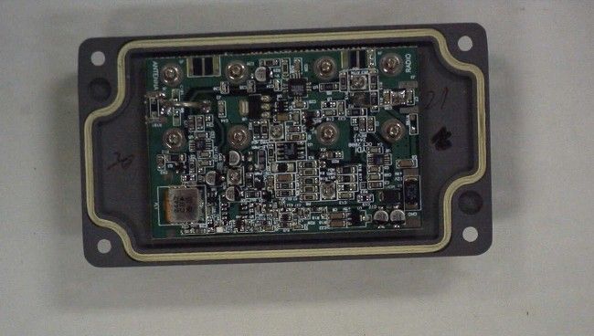
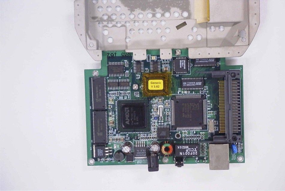
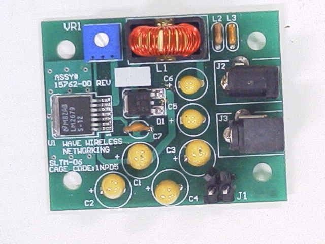
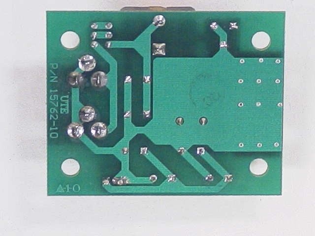
Operational Description for the NCBSLTMA. This is a 11 mega bit per second wireless local area network bridge radio that transceives a direct sequence spread spectrum carrier in the 2400-2483.5 MHz band. The data is input and output from a 10 Base T (Ethernet) connection and routed to a processor unit which formats the data and presents it to a Lucent PCMIA card to perform the conversion to and from DSSS. An external amplifier amplifies the RF signals on both receive and transmit. A 24 dBi gain parabolic reflector ‘grill’ type of antenna is also supplied. The internals of the NCBSLTMA consists of a power supply pcb, a processor unit, and a Lucent Technologies PCMIA card. The power supply pcb converts the incoming 18Vdc into voltages needed by the processor unit and the external amplifier. The functional configuration of the device is as a fixed mount, on a mast or other self supporting fixture. The weather proof radio is mounted physically close to the antenna and power and data is routed over a distance to the users facility. This is done to minimize the considerable loss that would otherwise exist if the radio were placed at the users facility and a length of coax were used between the facility and fixed mounted antenna. DC power is supplied to the external amplifier via a The Lucent Technologies card used in this radio performs the conversion to and from DSSS and modeming on a 2400 MHz carrier.
Schematics
AA BB CC DD EE 4 4 3 3 2 2 1 1 TX* RX INPUTLEVEL TX SOURCE PAD RX TX SOURCE V1 V2 -0.5V 2.4Ghz LPFilter STRIP STRIP STRIP INDUCTORS +32dB MAX TX* TX TX* SOURCE 6-22dB RX 4dB SOURCE PAD 3.5dB SET GAIN TO 14dBADJUSTABLE PAD DC Power CONFIDENTIAL 2440-FIF-FCC F Model AMP-2440-ONF-IF Young Design, Inc. 8000 Lee Hwy Falls Church, VA. 22042 11 Friday, June 08, 2001 TitleSize Document Number Rev Date: Sheet of 10V 10V 5V 5V 10V 5V 12V 12V -V 5V -V 12V 5V 12V R3 1K 1206 C5 100pF0805 C3 33pF0805 FL1 2.4MHz FIL-DFC-3P 1 345 2 C33 10pF0805 C13 100pF 0805 C12 33pF 0805 R5 8.2K 1206 C32 0.1uF1206 C8 10uF SFEC-B 50V + D1 ZC28 12ECT SOT23B 1 2 3 R2 1001206 C11 100pF0805 MOV1 SMBJ15 DO214AB R10.55W RW1S5CA R21 68 1206 U3 LM2903D SO8 VDD 8 OUT2 7 -2 6 +2 5 VSS 4 +1 3 -1 2 OUT1 1 R7 1K 1206 L4 0.5T14G3/8in 14GA IND400 J2 N-CONN TO ANT N-PCB J1 N-CONN TO INJECTOR N-PCB R4 8.2K1206 R13 68 1206 R15 68 1206 VR1 1K 3364W R171.1K1206 R24 T10K1206 C14 0.1uF 1206 R6 100K 1206 R23 OPEN 1206 C10 10pF 0805 L6 OPEN 0805 C38 .01uF0805 C37 33pF0805 C2 33pF0805 R122201206 C22 100pF 0805 C41 10pF0805 C40 10pF0805 C23 10pF0805 C24 33pF0805 D2 ZMM5240B 10VDL35 R16 1K 1206 R9 100K 1206 LED2 GRN LED 5LED100 R10220 1206 R11 470 0805 LED1 RED LED 5LED100 C29 100pF0805 C30 10uF SFEC-B 16V + R30120 1206 R29 270 1206 C34 0.7pF 0603 C36 0.7pF 0603 C35 1.3pF 0603 U7 RMPA24 50-53 RMPA RFIN 8 GND 7 GND 6 Vd1 5 Vd2 4 GND 3 RFOUT 2 GND 1 GND 9 Vg1 10 Vg2 11 GND 12 C26 .001uF 0603 U5 HMC174MS8 MSOP8 RF2 8 GND 7 GND 6 RF1 5 Vdd 4 RF 3 B 2 A 1 C28 100pF 0805 C42 33pF 0805 C27 OPEN 0805 C25 0.5pF 0603 C15 OPEN0805 C21 0 0805 Q3 2N7002 N-CHAN SOT23B Q2 DTA143EK SOT23B 1 32 R6327K0805 R22 220 1206 C43 .001uF 0805 U6 TCM829E SOT26 C+ 5 GND 4 C- 3 IN 2 OUT 1 NC 6 U8 LM317 AEMP SOT223 IN 3 ADJ 1 OUT 2 TAB 4 VR2 1K PWR 3364W C133pF0805 Q1 NDS351N SOT23B C18 0.1uF 1206 R27 1K 1206 R26 47 1206 JP1 2 POS JUMPERO3 1 3 2 R816 1206 R14 16 1206 VR3 1K 3364W VR4 1K PWR 3364W U2 HMC174MS8 MSOP8 RF2 8 GND 7 GND 6 RF1 5 Vdd 4 RF 3 B 2 A 1 C4 10pF0805 C45 10uF SFEC-B 50V + C44 10pF0805 Q6 NDC651N SOT26 N-CHAN 3 1 42 5 6 L3 22nH 0603 22nH U4B MGA-85563 SOT363 SLN-363 OUT 6 GND 5 Rbias 4 IN 3 GND 2 GND 1 C5233pF0603 R182200603 R19 24 0603 R202200603 R25 OPEN 0805 R28 150 0805 100 R32 100 0603 150 R31 OPEN 0603 470 L5 22nH0603 C9 0.1uF1206 C17 10uF SFEC-B 50V + U1 NJM78L05UA SOT89 IN 3 GND 2 OUT 1 C2033pF0805 C46B3.3nH0603 C31 10uF SFEC-B 16V + C39 10uF SFEC-B 50V + C51 22pF 0603 C50 .001uF 0603 C4922pF0603 U9 SGA-2163 SOT-363 SLN-363 OUT 6 GND 5 GND 4 IN 3 GND 2 N/C 1 R33B2200603 R352200603 R3415 0603 C47C33pF0603 C48B33pF0603 L10.5T22G3/8in22GAIND400 C7 100pF 0805 C6 0.1uF1206 GND +12Vin
Schematics
AA BB CC DD EE 4 4 3 3 2 2 1 1 SOURCE FILE->\ORCAD\DC-INJECTOR\DC-IN-C.DSN USE 22AWG WIRE FORINDUCTOR To Radio To Antenna Transmit LED if > ~175mA Receive LED if < ~150mA CONFIDENTIAL DCIN-C.DSN/DCIN-C1-FCC.SCH C1 +12VDC INJECTOR FOR AMP-2440P Young Design Inc. B 11 Thursday, July 20, 2000 TitleSize Document Number Rev Date: Sheet of +12V +12V +12V +12V R5 47K 1206 R2 43K1206 J2 N-CONNN-PCB J1 N-CONNN-PCB C1 4.7pF1206 L1 0.5T22G5/8" IND600 J3 BARREL JACKA DJ005 R8 47K 1206 MOV1 DO214ABSMBJ15A LED1 RED LED TX 5LED100 U1B LM358M SO8 - 65 7 U1A LM358M SO8 - 23 1 84 C4 .01uF1206 LED2 GRN LED RX 5LED100 R71K 1206 R41M 1206 C5 0.1uF1206 D1 S2GMS DO214AB F1 RUE110FUS200 R13 6.2K 1206 C2 10uF ELEC-A 35V + R3 47K 1206 R1 2 2Watt RES1000 J5 OPEN DJ005 +12VDC (optional source) R61K 1206 C9 .001uF1206 C10 0.1uF1206 D2 S2GMS DO214AB D4 BAV99SOT23B 12 3 C7 3.9pF1206 R148.2K 1206 C12 100pF 1206
Test Report
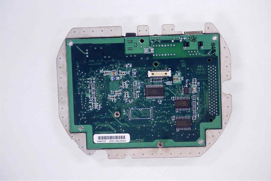
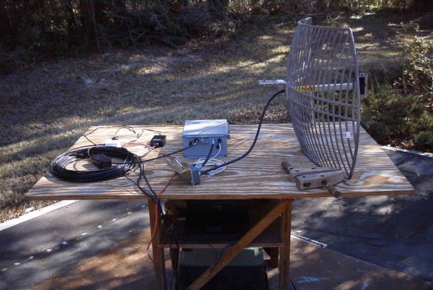
APPLICANT: SPEEDCOM WIRELESS CORP. FCC ID: NCBSLTMA TABLE OF CONTENTS TEST REPORT CONTAINING: PAGE 1.............LETTER REQUESTING CONFIDENTIALLY AND LETTER OF EXPLANATION PAGE 2.............LIST OF TEST EQUIPMENT AND TEST PROCEDURES PAGE 3.............PRODUCT DESCRIPTION PAGE 4.............POWERLINE CONDUCTED INTERFERENCE PAGE 5.............OCCUPIED BANDWIDTH AND POWER OUTPUT PAGE 6.............METHOD OF MEASURING RF CONDUCTED AND SPURIOUS EMISSIONS AT ANTENNA TERMINALS DATA PAGE 7.............RADIATION INTERFERENCE TEST DATA PAGE 8.............METHOD OF MEASURING RADIATED SPURIOUS EMISS. PAGE 9.............RADIATED SPURIOUS EMISSIONS INTO ADJACENT RESTRICTED BANDS PAGE 10.............POWER SPECTRAL DENSITY PAGE 11.............PROCESSING GAIN INFORMATION EXHIBIT ATTACHMENTS: EXHIBIT 1...........FCC ID LABEL SAMPLE EXHIBIT 2...........SKETCH OF FCC ID LABEL LOCATION EXHIBIT 3A..........FRONT VIEW EXTERNAL PHOTO EXHIBIT 3B..........REAR VIEW EXTERNAL PHOTO EXHIBIT 3C..........BOTTOM VIEW EXTERNAL PHOTO EXHIBIT 3D..........INTERNAL CHASSIS VIEW PHOTO EXHIBIT 3E..........INTERNAL PHOTO – COMPONENT VIEW- AMPLIFIER EXHIBIT 3F..........INTERNAL PHOTO – COMPONENT VIEW – CPU EXHIBIT 3G..........INTERNAL PHOTO – SOLDER VIEW – CPU EXHIBIT 3H..........INTERNAL PHOTO – COMPONENT VIEW – POWER SUPPLY EXHIBIT 3I..........INTERNAL PHOTO – SOLDER VIEW – POWER SUPPLY EXHIBIT 4...........BLOCK DIAGRAM EXHIBIT 5...........INSTRUCTION MANUAL EXHIBIT 6A-6B.......POWERLINE CONDUCTED PLOTS EXHIBIT 7...........6dB BANDWIDTH PLOT EXHIBIT 8...........SPECTRAL DENSITY PLOT EXHIBIT 9...........BANDEDGE PLOT EXHIBIT 10..........TEST SETUP UP PHOTOGRAPH EXHIBIT 11..........REQUEST FOR CONFIDENTIALITY LETTER EXHIBIT 12..........UNIQUE CONNECTOR LETTER EXHIBIT 13A.........SCHEMATIC – AMP-2440-XXF EXHIBIT 13B.........SCHEMATIC – AMP-2440-ONF-IF EXHIBIT 13C.........SCHEMATIC – 12VDC INJECTOR FOR AMP-2440 EXHIBIT 14..........PROCESSING GAIN TEST DATA REPORT NO.: T:\CUS\S\SPEEDCOM\702U0\702U0RPT.DOC TABLE OF CONTENTS LIST 6 April 2001 Federal Communications Commission Authorization and Evaluation Division 7435 Oakland Mills Road Columbia, MD 21046 SUBJECT: SPEEDCOM WIRELESS Corporation Wave Wireless Networking FCCID: NCBSLTMA To Whom It May Concern: The attached application is for a direct sequence spread spectrum assembly, made up of the Bridge/Radio (FCC ID: IMRWLPCE24H), 50 foot of coax, an amplifier, 10 foot of coax, a lightning arres- tor, and a parabolic antenna. This system has only one type of antenna, a parabolic dish that has a gain of 24dBi. SPEEDCOM WIRELESS CORP. purchases standard antennas from the manufacturers with unique connectors on them. The antenna is intended to be used outside. Should you have any questions or require any further information with regards to this, please feel free to contact me. Sincerely, Mario R. de Aranzeta C.E.T. MRD/sh Encl. APPLICANT: SPEEDCOM WIRELESS CORP. FCCID: NCBSLTMA REPORT #: T:\CUS\S\SPEEDCOM\702U0\702U0RPT.DOC PAGE #: 1 TEST EQUIPMENT LIST 1. Spectrum Analyzer: HP 8566B-Opt 462, S/N 3138A07786, w/ preselector HP 85685A, S/N 3221A01400, Quasi-Peak Adapter HP 8565OA, S/N 3303A01690 & Preamplifier HP 8449B-OPT H02, S/N 3008A00372 2. Biconnical Antenna: Eaton Model 94455-1, S/N 1057 3. Log-Periodic Antenna: Electro-Metrics Model EM-6950, S/N 632 4. Double-Ridged Horn Antenna: Electro-Metrics Model RGA-180, 1-18 GHz, S/N 2319 5. Line Impedance Stabilization Network: Electro-Metrics Model ANS-25/2, S/N 2604 6. AC Voltmeter: HP Model 400FL, S/N 2213A14499 7. Peak Power Meter HP 8900C With Peak Power Sensor HP 84811A TEST PROCEDURE GENERAL: This report shall NOT be reproduced except in full without the written approval of TIMCO ENGINEERING, INC. Shielded interface cables were used in all cases except for cables connecting to the telephone line and the power cords. A test program was run which simulated a normal data transmission on a network. POWER LINE CONDUCTED INTERFERENCE: The procedure used was ANSI STAN- DARD C63.4-1992 using a 50uH LISN. Both lines were observed with the UUT transmitting. The bandwidth of the spectrum analyzer was 10kHz with an appropriate sweep speed. The ambient temperature of the UUT was 76°F with a humidity of 55%. BANDWIDTH 6.0dB: The measurements were made with the spectrum analyzer's resolution bandwidth(RBW)=1.0MHz and the video bandwidth(VBW) =3.0MHz and the span set as shown on plot. POWER OUTPUT: The RF power output was measured at the antenna feed point using a peak power meter. ANTENNA CONDUCTED EMISSIONS: The RBW=100KHz, VBW=300KHz and the span set to 10.0MHz and the spectrum was scanned from 30MHz to the 10th Harmonic of the fundamental. Above 1.0GHz the resolution bandwidth was 1.0MHz and the VBW = 3.0MHz and the span to 50MHz. RADIATION INTERFERENCE: The test procedure used was ANSI STANDARD C63.4-1992 using a HEWLETT PACKARD spectrum analyzer with a prese- lector. The bandwidth(RBW) of the spectrum analyzer was 100kHz up to 1GHz and 1.0MHz above 1GHz with an appropriate sweep speed. The VBW above 1.0GHz was = 3.0MHz. The analyzer was calibrated in dB above a microvolt at the output of the antenna. The ambient temperature of the UUT was 53°F with a humidity of 17%. APPLICANT: SPEEDCOM WIRELESS CORP. FCCID: NCBSLTMA REPORT #: T:\CUS\S\SPEEDCOM\702U0\702U0RPT.DOC PAGE #: 2 PRODUCT DESCRIPTION: The NCBSLTMA is a direct sequence spread spectrum radio that operates in the 2433 MHz frequency. APPLICANT: SPEEDCOM WIRELESS CORP. FCCID: NCBSLTMA REPORT #: T:\CUS\S\SPEEDCOM\702U0\702U0RPT.DOC PAGE #: 3 APPLICANT: SPEEDCOM WIRELESS CORP. FCC ID: NCBSLTMA NAME OF TEST: POWER LINE CONDUCTED INTERFERENCE RULES PART NUMBER: 15.107(a) REQUIREMENTS: .45 - 30 MHz 250 uV OR 47.96 dBuV TEST PROCEDURE: ANSI STANDARD C63.4-1992. The spectrum was scanned from .45 to 30 MHz. TEST DATA: THE HIGHEST EMISSION READ FOR LINE 1 WAS 104 uV @ 22.61 MHz. THE HIGHEST EMISSION READ FOR LINE 2 WAS 97.70 uV @ 20.54 MHz. THE PLOTS IN EXHIBITS 6A-6B REPRESENT THE EMISSIONS TA…
Text truncated - open the document above for the full version.
Contact Information
Applicant
John Dyndul(Product Certification Manager)
Test Firm
Timco Engineering, Inc.S Sanders
Technical Specifications
| # | Rule Parts | Frequency Range | Power Output |
|---|---|---|---|
| 1 | 15C | 2.43 GHz - 2.43 GHz | 160.00 mW |
Other Applications from Wave Wireless Networking
NCBSL9101A
Dec 11, 2003Spread Spectrum Transmitter
Equipment Class
DTS - Digital Transmission System
NCBSL9102A
Dec 09, 2003SPREAD SPECTRUM TRANSMITTER
Equipment Class
DTS - Digital Transmission System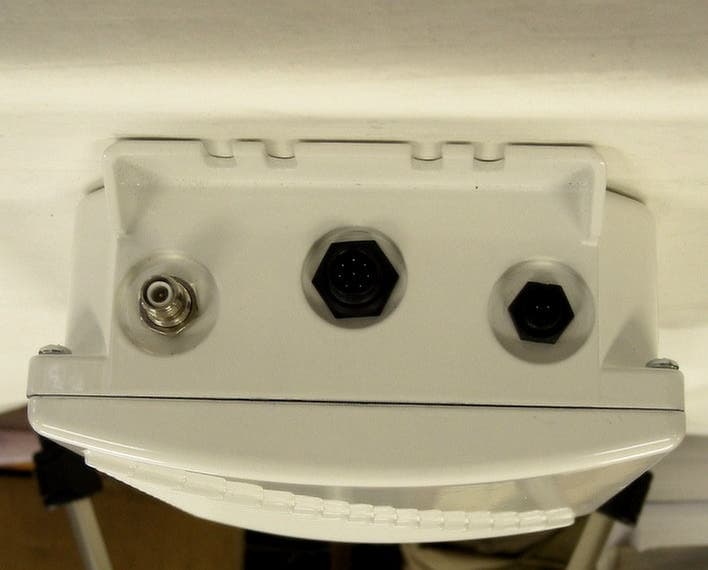
NCBSL9102
May 08, 2002Spread Spectrum Transmitter
Equipment Class
DTS - Digital Transmission System
NCBSL9101
May 06, 2002Spread Spectrum Transmitter
Equipment Class
DTS - Digital Transmission System
NCBSLXE2
Apr 11, 2002Spread Spectrum Transmitter
Equipment Class
DSS - Part 15 Spread Spectrum Transmitter