NCM-WT500Water and Temperature Sensor
Option (Crescent NV)
Click to zoom
Application Details
- Equipment Class
- DSS - Part 15 Spread Spectrum Transmitter
- Date of Grant
- Jun 06, 2021
- Application Purpose
- Original Equipment
- Date of Application
- May 31, 2021
- Equipment Note
- Water and Temperature Sensor
- Frequency Range
- 902.30000000 - 914.90000000
- Company
- Option (Crescent NV)
- Country
- Belgium
Documents & Files
Document Text
Text extracted from the exhibit documents filed with the FCC. Open a document above to read the original.
Users Manual
To Whom It May Concern: FCC ID: NCM-WT500 IC: 2734A-WT500 FCC § 15.19 Labelling requirements This device complies with part 15 of the FCC Rules and Innovation, Science and Economic Development Canada (ISED) license-exempt RSS standard(s). Operation is subject to the following two conditions: (1) This device may not cause harmful interference, and (2) this device must accept any interference received, including interference that may cause undesired operation. FCC § 15.21 Information to user Changes or modifications not expressly approved by the party responsible for compliance could void the user’s authority to operate the equipment. FCC §15.105 statement This equipment has been tested and found to comply with the limits for a Class B digital device, pursuant to part 15 of the FCC Rules. These limits are designed to provide reasonable protection against harmful interference in a residential installation. This equipment generates, uses and can radiate radio frequency energy and, if not installed and used in accordance with the instructions, may cause harmful interference to radio communications. However, there is no guarantee that interference will not occur in a particular installation. If this equipment does cause harmful interference to radio or television reception, which can be determined by turning the equipment off and on, the user is encouraged to try to correct the interference by one or more of the following measures: —Reorient or relocate the receiving antenna. —Increase the separation between the equipment and receiver. —Connect the equipment into an outlet on a circuit different from that to which the receiver is connected. —Consult the dealer or an experienced radio/TV technician for help. RF Exposure Requirements To comply with FCC RF exposure compliance requirements, the device must be installed to provide a separation distance of at least 20 cm from all persons. ISED CANADA Statements Le présent appareil est conforme aux CNR d' Innovation, Sciences et Développement économique Canada applicables aux appareils radio exempts de licence. L'exploitation est autorisée aux deux conditions suivantes : (1) l'appareil ne doit pas produire de brouillage, et (2) l'utilisateur de l'appareil doit accepter tout brouillage radioélectrique subi, même si le brouillage est susceptible d'en compromettre le fonctionnement. Canada Class B statement This Class B digital apparatus complies with Canadian ICES-003 Cet appareil numérique de la classe B est conforme à la norme NMB-003 du Canada. RF Exposure Requirements This equipment complies with Canada radiation exposure limits set forth for an uncontrolled environment. This equipment should be installed and operated with minimum distance 20cm between the radiator and your body. Déclaration d’exposition aux radiations: Cet équipement est conforme aux limites d’exposition aux rayonnements du Canada établies pour un environnement non contrôlé. Cet équipement doit être installé et utilisé avec un minimum de 20 cm de distance entre la source de rayonnement et votre corps. The mentioned statements and paragraphs in this document will be placed in a prominent location in the final user manual. Signature Jasna Papuga Option (Crescent NV) Gaston Geenslaan 14 3001 Leuven Belgium +32 16 317 411 [email protected]
Users Manual
WT500 Device User Manual Basic Overview The WT500 is designed to detect the physical presence of water or when ambient temperature meets a user defined threshold. When the WT500 detects water or abnormal temperature under normal operating conditions, the sensor will go into an alarm state. In an alarm state, the device will go into an audible alarm while triggering an alarm to the device group that it is assigned to. Customer Support GreenField Direct, LLC 14015 238 th Street Greenwood, NE 68366 www.pipeburstpro.com/contact E-Mail: [email protected] Phone: 866-466-LEAK (5325) Hours of Operation: Weekdays 8:00 AM –5:00 PM CT Warranty Information PipeBurst Pro Products 2/5/7 Year Limited Warranty Please visit: www.pipeburstpro.com/warrantyto review full warranty details ©2021 GreenField Direct, LLC rev.4.15.2021 WT500 Device Features Dimensions Ø 2-7/8” x 1-1/8” Power Source CR123A Built-in Sensors Gold Plated Water Sensor Pins Ambient Air Temperature Sensor Tamper Alert Sensor Movement Sensor Voltage3 VDC HousingWhite ABS Plastic Audible Notification InternalSpeaker Wireless Frequency 915 MHz Input Port Options Disabled Water Sensor (standard) Installation of a WT Device Device association to a Gateway 1.On your ionleaksdashboard, go to the device tab and select “New Device”. 2.Enter in the device ID and device key for the WT500 and click “Add”. Repeat this step for each sensor that needs to be added before proceeding to step 3. 3.Remove the battery pull tab from the device to power it on. The device will beep as part of its power up sequence. WT Device Placement 1.Place one WT Device at each desired plumbing fixture, appliance, or other location. 2.Once a WT Device is in its location, open and close the lid of the device to create a tamper event message. This message can be used as a test for functionality and signal strength indication on ionleaks.com 3.Leave the device in its location and monitor through ionleaks.com to check for connection WT Device Customizable Options Warnings and Precautions •WT Devices operate on communications frequencies which are subject to FCC rules and regulations. Specific information about device conformity can be found at: https://www.pipeburstpro.com/disclaimers/ •Placing WT Devices near large metal objects may decrease or block wireless coverage. •Positioning a WT Device for water detection: •WT Device must be placed below the plumbing fixture or appliance it is monitoring. •WT Device Water Sensor Pins must be facing the surface the WT Device is sitting on to function properly. •End User is responsible that the WT Device functionality and installation meets the desired requirements. •This manual may be updated or changed without advanced notice. •To learn about changing settings via ionleaks.com, refer to the ionleaks.com User Manual. Wireless Regulatory Information Model: WT500 FCC ID: NCM-WT500 IC: 2734A-WT500 Frequency Range: 915 MHz SettingDescription Water Sensor When the water sensing pins are wet, the device will send an alarm state to the Group. Temperature Sensor Temperature alarm is sent when the sensor meets a user defined temperature threshold. Movement SensorThe sensor can detect and record when it is moved. Tamper AlertIf the lid of the sensor is removed, a tamper alert is triggered. Data Recording Interval The sensor is set to check-in with the system at a user determined amount of time. Maintenance Tips for Optimal Device Performance •Always replace batteries after a water detection. •Change batteries when low battery alert is received. •Clean WT Device housing on a regular basis. Ensure Water Sensing Pins are clear of dust and debris.
Cover Letter(s)
Option nv, Gaston Geenslaan 14, 3001 Leuven - Belgium - Tel +32 16 317 411 - Fax +32 16 207 164 ANTENNA MEASUREMENT Report Publication date: 01 december, 2020 Revision: V002 ANTENNA MEASUREMENT Report Page 1 of 10 This document is Option Confidential - it may not be duplicated, neither distributed externally without prior and written permission of Option NV. About this document Confidentiality All data and information contained or disclosed by this document is confidential and proprietary of Option NV, and all rights therein are expressly reserved. By accepting this document, the recipient agrees that this information is held in confidence and in trust and will not be used, copied, reproduced in whole or in part, nor its contents revealed in any manner to others without prior and written permission of Option NV. Version History Date Version Author Revision Remarks 01 December 2020 V001 Chris De Vos ANTENNA MEASUREMENT Report Page 2 of 10 This document is Option Confidential - it may not be duplicated, neither distributed externally without prior and written permission of Option NV. Table of contents 1 USED MEASUREMENT EQUIPMENT REFERENCES .......................................................... 3 2 PRODUCT OVERVIEW ............................................................................................................... 3 3 ANTENNA MEASUREMENT SETUP ........................................................................................ 3 4 MEASUREMENT RESULTS ....................................................................................................... 4 4.1 MAIN ANTENNA .......................................................................................................................... 4 5 REFERENCES ............................................................................................................................. 10 ANTENNA MEASUREMENT Report Page 3 of 10 This document is Option Confidential - it may not be duplicated, neither distributed externally without prior and written permission of Option NV. 1 USED MEASUREMENT EQUIPMENT REFERENCES Equipment ser number Antenna chamber Satimo SG32 Network analyser R&S ZVB-8 2 PRODUCT OVERVIEW The measurements were carried out on PCB antenna as in Error! Reference source not found. Fig. 1 3 ANTENNA MEASUREMENT SETUP Fig. 2 illustrates the near-field coordinate system and orientations.. Efficiency of the antenna is measured. ANTENNA MEASUREMENT Report Page 4 of 10 This document is Option Confidential - it may not be duplicated, neither distributed externally without prior and written permission of Option NV. Fig. 2 Fig. 3 4 MEASUREMENT RESULTS 4.1 Main antenna 4.1.1.1 Matching main antenna Phi X Y Z Elevation 1 (Phi 90) Elevation 2 (Phi 0) Azimuth Pogo pins bottom ANTENNA MEASUREMENT Report Page 5 of 10 This document is Option Confidential - it may not be duplicated, neither distributed externally without prior and written permission of Option NV. Return loss for both frequency bands < 6dB 4.1.1.2 Efficiency Main antenna Low Band (868Mhz) 4.1.1.3 Peak Gain Main antenna Low Band (868Mhz) ANTENNA MEASUREMENT Report Page 6 of 10 This document is Option Confidential - it may not be duplicated, neither distributed externally without prior and written permission of Option NV. ANTENNA MEASUREMENT Report Page 7 of 10 This document is Option Confidential - it may not be duplicated, neither distributed externally without prior and written permission of Option NV. 4.1.1.4 Patterns Main Antenna Low band Elevation1 Elevation 2 Azimuth ANTENNA MEASUREMENT Report Page 8 of 10 This document is Option Confidential - it may not be duplicated, neither distributed externally without prior and written permission of Option NV. 4.1.1.5 Efficiency Main antenna High Band (902-928Mhz) 4.1.1.6 Peak Gain Main antenna High Band (902-928Mhz) ANTENNA MEASUREMENT Report Page 9 of 10 This document is Option Confidential - it may not be duplicated, neither distributed externally without prior and written permission of Option NV. 4.1.1.7 Patterns Main Antenna High band Elevation1 Elevation 2 Azimuth ANTENNA MEASUREMENT Report Page 10 of 10 This document is Option Confidential - it may not be duplicated, neither distributed externally without prior and written permission of Option NV. 5 REFERENCES Ref Reference documents Owner
Cover Letter(s)
RF_160, Issue 04 Declaration of Authorization We Name: Option (Crescent NV) Address: Gaston Geenslaan 14. City: Leuven. Country: Belgium. Declare that: Name Representative of agent: Abdellah Ahakki, Imad Hjije. (1) Agent Company name: 7layers GmbH Address: Borsigstrasse 11 City: 40880 Ratingen Country Germany is authorized to apply for Certification of the following product(s): Product description: Water and Temperature Sensor. Type designation: WT500.... Trademark: Option. Validity/ expiry date on our behalf. Date: 31/05/2021.. City: Leuven.. Name: Jasna Papuga.. (2) Function: Certification engineer...................... Signature: . Notes: (1): Required for FCC application (2): For FCC it must be the Grantee Code “owner” or the authorized agent.
Cover Letter(s)
FCC, Request for non-disclosure Date: 21-Nov-2018 RF_501, Issue 8 Page 1 of 1 Company Name: Option NV Address : Gaston Geenslaan 14 City: Leuven Country: Belgium To: Telefication B.V., Dept. FCC TCB Edisonstraat 12A 6902 PK ZEVENAAR The Netherlands Subject: Request for confidentiality FCC ID: NCM-WT500 Reference number: ###### Dear FCC TCB, 1. Long-Term Confidentiality Pursuant to 47 CFR Section 0.459(a) & (b), we hereby requests non-disclosure and confidential treatment of the following materials submitted in support of FCC certification application: Bill(s) of Material Block Diagrams Operational Description Schematic Diagrams Tune-up Procedure Above materials contain secrets, proprietary and technical information, which would customarily be guarded from competitors under 47 CFR, section 0.457(d)(2). Disclosure or publication or any portion of this company confidential material to other parties could cause substantial competitive harm and provide unjustified benefits for competitors. 2. Short-Term Confidentiality (STC) Pursuant to Public Notice DA 04-1705 of the Commission’s policy, in order to comply with the marketing regulations in 47 CFR §2.803 and the importation rules in 47 CFR §2.1204, a pplicant hereby requests Short-Term Confidential treatment of the following materials (See notes below): Internal Photos User’s Manual Test Set-up Photos External Photos Justification: These documents contain detaild system and equipment description and related information about the product, which Harman International Industries, Inc. considers to be proprietary. This information should never get into the possession of competitors, which would be harmful for our business Date: 05,27,2021 Name and signature of applicant: Abdellah Ahakki Notes: 1) A document or type of document can only have ONE type of confidentiality! 2) Short-Term confidentiality is in principle for 45 days from date of grant; it can be extended max 3 times (total time 180 days max.)! The planned date should stated in the RF731 application form. 3) FCC must be informed when marketing begins earlier. 4) Release takes place automatically thus extension must be requested in time. Telefication does not remind you of this! 5) Request for extension or for release must be received by Telefication at least 7 days before date of actual marketing or before expiration of the STC period
External Photos
Water and Temperature Sensor External photos Model: WT500 Water and Temperature Sensor (WT500) External photos Author: Jasna Papuga Version: 1 Date: 05/21/2021 Page: 2 of 4 This document is Option Confidential - it may not be duplicated, neither distributed externally without prior and written permission of Option (Crescent NV). About this document Overview and purpose This document presents the internal and external photos of the Water and Temperature Sensor (WT500). Confidentiality All data and information contained or disclosed by this document is confidential and proprietary of Option (Crescent NV), and all rights therein are expressly reserved. By accepting this document, the recipient agrees that this information is held in confidence and in trust and will not be used, copied, reproduced in whole or in part, nor its contents revealed in any manner to others without prior and written permission of Option (Crescent NV). Version history Date Author Revision(s) Remarks 04/14/2021 Jasna Papuga v1 Initial version Water and Temperature Sensor (WT500) External photos Author: Jasna Papuga Version: 1 Date: 05/21/2021 Page: 3 of 4 This document is Option Confidential - it may not be duplicated, neither distributed externally without prior and written permission of Option (Crescent NV). EXTERNAL PHOTOS Top view Bottom view Water and Temperature Sensor (WT500) External photos Author: Jasna Papuga Version: 1 Date: 05/21/2021 Page: 4 of 4 This document is Option Confidential - it may not be duplicated, neither distributed externally without prior and written permission of Option (Crescent NV). Side view
ID Label/Location Info
Crescent nv - Gaston Geenslaan 14 - 3001 Leuven - Belgium - T +32 16 317 411 - F +32 16 207 164 - www.option.com RPR Leuven 0429.375.448 Label design and location Device information Commercial name: Water & Temp Sensor Model number/HVIN: WT500 Label design The label is laser marked on the housing. It is ink-free, permanent on the plastic housing. • FCC ID: NCM-WT500 • IC ID: 2734A-WT500 Label location FCC statement Due to the small size of the device, FCC statement specified under Part 15 of the FCC Rules will be placed in the user manual. • Diameter of the device: 75 mm • Diameter of the label area: 51.3 mm
Internal Photos
Water and Temperature Sensor Internal photos Model: WT500 Water and Temperature Sensor (WT500) Internal photos Author: Jasna Papuga Version: 1 Date: 05/21/2021 Page: 2 of 3 This document is Option Confidential - it may not be duplicated, neither distributed externally without prior and written permission of Option (Crescent NV). About this document Overview and purpose This document presents the internal and external photos of the Water and Temperature Sensor (WT500). Confidentiality All data and information contained or disclosed by this document is confidential and proprietary of Option (Crescent NV), and all rights therein are expressly reserved. By accepting this document, the recipient agrees that this information is held in confidence and in trust and will not be used, copied, reproduced in whole or in part, nor its contents revealed in any manner to others without prior and written permission of Option (Crescent NV). Version history Date Author Revision(s) Remarks 04/14/2021 Jasna Papuga v1 Initial version Water and Temperature Sensor (WT500) Internal photos Author: Jasna Papuga Version: 1 Date: 05/21/2021 Page: 3 of 3 This document is Option Confidential - it may not be duplicated, neither distributed externally without prior and written permission of Option (Crescent NV). INTERNAL PHOTOS Top view – PCB + housing Bottom view – PCB + housing
RF Exposure Info
MDE_OPTION_2009_MPEa Page 1 of 4 Maximum Permissible Exposure EN 62311:2008 WT500 Water and Temperature Sensor FCC ID: NCM-WT500 IC: 2734A-WT500 Test Report Reference: MDE_OPTION_2009_MPEa To whom it may concern, please find our Maximum Permissible Exposure calculations for LoRa Sensor. Best Regards i.A. Abdellah Ahakki MDE_OPTION_2009_MPEa Page 2 of 4 Administrative Data: Testing Laboratory Company Name: 7layers GmbH Address: Borsigstr. 11 40880 Ratingen Germany Project Data Responsible for report: Mr. Abdellah Ahakki Date of Report: 2021-05-25 Testing Period: 2021-01-12 to 2021-04-08 Applicant Data Company Name: Option (Crescent NV) Address: Gaston Geenslaan 14 3001 Leuven Belgium Contact Person: Jasna Papuga Manufacturer Data Company Name: please see Applicant data Address: - - - Contact Person: - MDE_OPTION_2009_MPEa Page 3 of 4 Test object Data General Description of Radio Device Kind of Device product description LoRa Sensor Product name Water and Temperature Sensor Type WT500 Declared EUT data by the supplier Voltage Type DC (Battery powered) Voltage Level 3V Antenna / Gain Integral / -2 dBi Tested Modulation Type FSK General product description The EUT is a water and Temperature sensor with LoRa technology Specific product description for the EUT The EUT is a LoRaWAN transceiver in the 900 MHz band. Relevant for this report is the 125 kHz hopping mode which is implemented as FHSS for link setup and as hybrid with only 8 channels during established communication. EUT ports (connected cables during testing): Enclosure Tested datarates Data rate settings LS5 to 12 are supported by the test software, the worst case of the modes was tested for each test case (see test results). Special software used for testing The local TX test modes were set using “LoraNode” software provided by applicant (non-hopping mode tests). Tera Term was used to send commands for hopping mode tests. Tera Term together with Macros and prepared templates in the Option CloudGate LORA gateway, which were provided by the applicant, were used for dwell time tests. MDE_OPTION_2009_MPEa Page 4 of 4 Maximum Permissible Exposure (as specified in Table 2 in EN 1999/519-EC) Frequency range (MHz) Power density (mW/cm²) 400 – 2000 f/2000 2000 - 300000 1 mW/cm² Calculations 900 MHZ band Equation OET bulletin 65, page 18, edition 97-01: S = P*G / (4πR²) S = power density P = power input to the antenna G = power gain of the antenna in the direction of interest relative to an isotropic radiator R = distance to the centre of radiation of the antenna Remark: • only worst-case values are listed in the table above. Conclusion: all results are within the MPE Limit
Test Report
Test Laboratory: 7layers GmbH Borsigstrasse 11 40880 Ratingen Germany Note: The following test results relate only to the devices specified in this document. This report shall not be reproduced in parts without the written approval of the test laboratory. 7layers GmbH Geschäftsführer/ Borsigstraße 11 Managing Directors: Registergericht/registered: a Bureau Veritas 40880 Ratingen, Germany Frank Spiller Düsseldorf HRB 75554 Group Company T +49 (0) 2102 749 0 Bernhard Retka USt-Id.-Nr./VAT-No. DE203159652 F +49 (0) 2102 749 350 Alexandre Norré-Oudard Steuer-Nr./TAX-No. 147/5869/0385 www.7layers.com Commerzbank AG Account No. 303 016 000 Bank Code 300 400 00 IBAN DE81 3004 0000 0303 0160 00 Swift Code COBADEFF FCC Measurement/Technical Report on WT500 Water and Temperature Sensor FCC ID: NCM-WT500 IC: 2734A-WT500 Test Report Reference: MDE_OPTION_2009_FCC_01_rev01 TEST REPORT REFERENCE: MDE_OPTION_2009_FCC_01_rev01 Page 2 of 65 Table of Contents 1 Applied Standards and Test Summary 3 1.1 Applied Standards 3 1.2 FCC-IC Correlation Table 4 1.3 Measurement Summary 5 2 Revision History / Signatures 8 3 Administrative Data 9 3.1 Testing Laboratory 9 3.2 Project Data 9 3.3 Applicant Data 9 3.4 Manufacturer Data 10 4 Test object Data 11 4.1 General EUT Description 11 4.2 EUT Main components 12 4.3 Ancillary Equipment 12 4.4 Auxiliary Equipment 13 4.5 EUT Setups 13 4.6 Operating Modes / Test Channels 13 4.7 Product labelling 14 5 Test Results 15 5.1 Occupied Bandwidth (20 dB) 15 5.2 Occupied Bandwidth (99%) 18 5.3 Peak Power Output 20 5.4 Spurious RF Conducted Emissions 23 5.5 Transmitter Spurious Radiated Emissions 27 5.6 Band Edge Compliance Conducted 38 5.7 Power Density 42 5.8 Channel Separation 46 5.9 Dwell Time 49 5.10 Number of Hopping Frequencies 53 6 Test Equipment 56 7 Antenna Factors, Cable Loss and Sample Calculations 58 7.1 LISN R&S ESH3-Z5 (150 kHz – 30 MHz) 58 7.2 Antenna R&S HFH2-Z2 (9 kHz – 30 MHz) 59 7.3 Antenna R&S HL562 (30 MHz – 1 GHz) 60 7.4 Antenna R&S HF907 (1 GHz – 18 GHz) 61 7.5 Antenna EMCO 3160-09 (18 GHz – 26.5 GHz) 62 7.6 Antenna EMCO 3160-10 (26.5 GHz – 40 GHz) 63 8 Measurement Uncertainties 64 9 Photo Report 65 TEST REPORT REFERENCE: MDE_OPTION_2009_FCC_01_rev01 Page 3 of 65 1 APPLIED STANDARDS AND TEST SUMMARY 1.1 APPLIED STANDARDS Type of Authorization Certification for an Intentional Radiator. Applicable FCC Rules Prepared in accordance with the requirements of FCC Rules and Regulations as listed in 47 CFR Ch.1 Parts 2 and 15 (10-1-19 Edition). The following subparts are applicable to the results in this test report. Part 2, Subpart J - Equipment Authorization Procedures, Certification Part 15, Subpart C – Intentional Radiators § 15.201 Equipment authorization requirement § 15.207 Conducted limits § 15.209 Radiated emission limits; general requirements § 15.247 Operation within the bands 902-928 MHz, 2400-2483.5 MHz Note: The tests were selected and performed with reference to the FCC Public Notice “Guidance for Compliance Measurements on Digital Transmission System, Frequency Hopping Spread Spectrum System, and Hybrid System Devices Operating under Section 15.247 of the FCC Rules, 558074 D01 15.247 Meas Guidance v05r02, 2019-04-02”. ANSI C63.10–2013 is applied. TEST REPORT REFERENCE: MDE_OPTION_2009_FCC_01_rev01 Page 4 of 65 1.2 FCC-IC CORRELATION TABLE Correlation of measurement requirements for FHSS (e.g. Bluetooth ® ) equipment from FCC and IC FHSS equipment Measurement FCC reference IC reference Conducted emissions on AC Mains § 15.207 RSS-Gen Issue 5: 8.8 Occupied bandwidth § 15.247 (a) (1) RSS-247 Issue 2: 5.1 (b) Peak conducted output power § 15.247 (b) (1), (4) RSS-247 Issue 2: 5.4 (b) Transmitter spurious RF conducted emissions § 15.247 (d) RSS-Gen Issue 5: 6.13/8.9/8.10; RSS-247 Issue 2: 5.5 Transmitter spurious radiated emissions § 15.247 (d); § 15.209 (a) RSS-Gen Issue 5: 6.13 / 8.9/8.10; RSS-247 Issue 2: 5.5 Band edge compliance § 15.247 (d) RSS-247 Issue 2: 5.5 Dwell time § 15.247 (a) (1) (iii) RSS-247 Issue 2: 5.1 (d) Channel separation § 15.247 (a) (1) RSS-247 Issue 2: 5.1 (b) No. of hopping frequencies § 15.247 (a) (1) (iii) RSS-247 Issue 2: 5.1 (d) Hybrid systems (only) § 15.247 (f); § 15.247 (e) RSS-247 Issue 2: 5.3 Antenna requirement § 15.203 / 15.204 RSS-Gen Issue 5: 8.3 Receiver spurious emissions – - TEST REPORT REFERENCE: MDE_OPTION_2009_FCC_01_rev01 Page 5 of 65 1.3 MEASUREMENT SUMMARY 47 CFR CHAPTER I FCC PART 15 Subpart C §15.247 § 15.247 (a) (1) Occupied Bandwidth (20 dB) The measurement was performed according to ANSI C63.10 Final Result OP-Mode Radio Technology, Operating Frequency Setup Date FCC IC Lora (FHSS), high S01_AF02 2021-03-29 Passed Passed Lora (FHSS), low S01_AF02 2021-03-29 Passed Passed Lora (FHSS), mid S01_AF02 2021-03-29 Passed Passed 47 CFR CHAPTER I FCC PART 15 Subpart C §15.247 IC RSS-Gen & IC TRC-43; Ch. 6.7 & Ch. 8 Occupied Bandwidth (99%) The measurement was performed according to ANSI C63.10 Final Result OP-Mode Radio Technology, Operating Frequency Setup Date FCC IC Lora (FHSS), high S01_AF02 2021-03-29 N/A Performed Lora (FHSS), low S01_AF02 2021-03-29 N/A Performed Lora (FHSS), mid S01_AF02 2021-03-29 N/A Performed 47 CFR CHAPTER I FCC PART 15 Subpart C §15.247 § 15.247 (b) (1) (2) Peak Power Output The measurement was performed according to ANSI C63.10 Final Result OP-Mode Radio Technology, Operating Frequency, Measurement method Setup Date FCC IC Lora (FHSS), high, conducted S01_AF02 2021-03-29 Passed Passed Lora (FHSS), low, conducted S01_AF02 2021-03-29 Passed Passed Lora (FHSS), mid, conducted S01_AF02 2021-03-29 Passed Passed 47 CFR CHAPTER I FCC PART 15 Subpart C §15.247 § 15.247 (d) Spurious RF Conducted Emissions The measurement was performed according to ANSI C63.10 Final Result OP-Mode Radio Technology, Operating Frequency Setup Date FCC IC Lora (FHSS), high S01_AF02 2021-03-31 Passed Passed Lora (FHSS), low S01_AF02 2021-03-31 Passed Passed Lora (FHSS), mid S01_AF02 2021-03-31 Passed Passed TEST …
Text truncated - open the document above for the full version.
Test Setup Photos
7layers GmbH Geschäftsführer/ Borsigstraße 11 Managing Directors: Registergericht/registered: a Bureau Veritas 40880 Ratingen, Germany Frank Spiller Düsseldorf HRB 75554 Group Company T +49 (0) 2102 749 0 Bernhard Retka USt-Id.-Nr./VAT-No. DE203159652 F +49 (0) 2102 749 350 Alexandre Norré-Oudard Steuer-Nr./TAX-No. 147/5869/0385 www.7layers.com Commerzbank AG Account No. 303 016 000 Bank Code 300 400 00 IBAN DE81 3004 0000 0303 0160 00 Swift Code COBADEFF Photo Report on Test Setups WT500 Water and Temperature Sensor FCC ID: NCM-WT500 IC: 2734A-WT500 Test Report Reference: MDE_OPTION_2009_FCC_Photo_Setups TEST REPORT REFERENCE: MDE_OPTION_2009_FCC_Photo_Setups Page 2 of 4 Photo 1: Test setup for radiated measurements below 30 MHz Photo 2: Test setup for radiated measurements below 1 GHz TEST REPORT REFERENCE: MDE_OPTION_2009_FCC_Photo_Setups Page 3 of 4 Photo 3: Test setup for radiated measurements above 1 GHz Photo 5: Test setup for radiated measurements EUT detail TEST REPORT REFERENCE: MDE_OPTION_2009_FCC_Photo_Setups Page 4 of 4 Photo 6: Test setup for conducted measurements Photo 7: Test setup for conducted measurements EUT Detail
Contact Information
Applicant
Joost van der Velden(CEO)
Technical Contact
Non-Technical Contact
Option (Crescent NV)Jasna Papuga
[email protected]3216317411
Test Firm
7layers GmbHBernhard Retka
Technical Specifications
| # | Rule Parts | Frequency Range | Power Output |
|---|---|---|---|
| 1 | 15C | 902.3 MHz - 914.9 MHz | 93.00 mW |
Other Applications from Option (Crescent NV)

NCM-CG2132
Sep 21, 2022LoRaWAN 86x/9xx Expansion card
Equipment Class
DTS - Digital Transmission System
NCMOCG2101
Feb 27, 2013CloudGate 802.11abgn Wireless LAN Card
Equipment Class
NII - Unlicensed National Information Infrastructure TX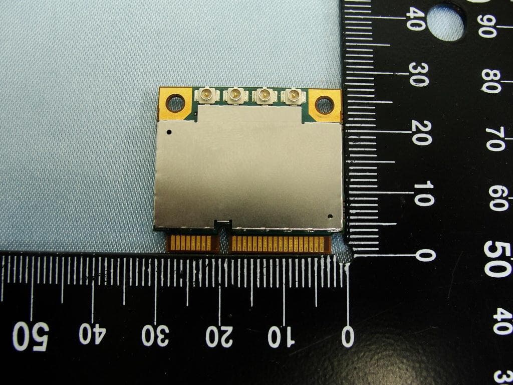
NCMOMO6792
Feb 24, 2013GTM679W
Equipment Class
JBP - Part 15 Class B Computing Device PeripheralNCMOGI0644
Jun 17, 2012GSM/UMTS/WLAN USB Modem GI0644
Equipment Class
PCB - PCS Licensed Transmitter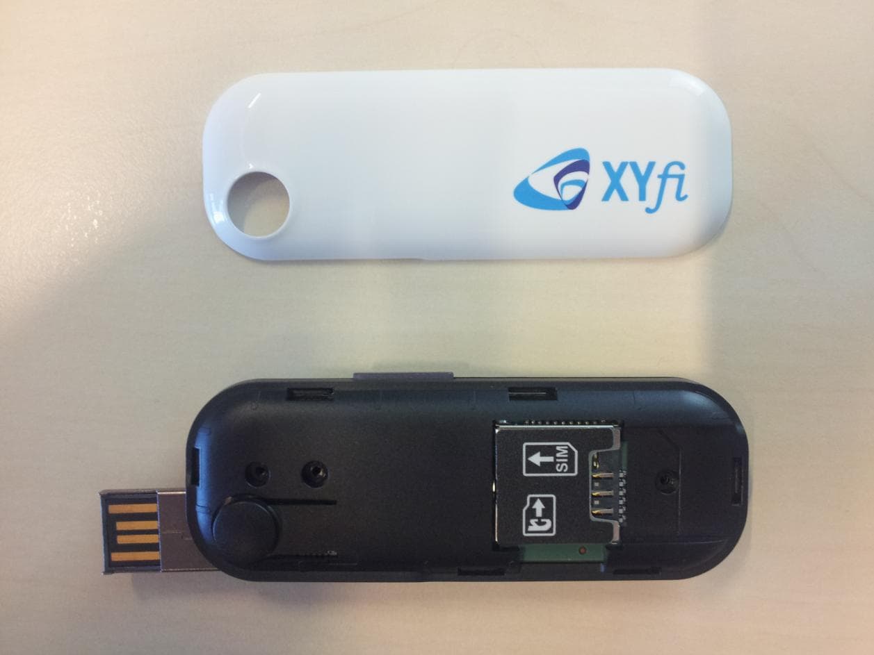
NCMOGI0643
Dec 22, 2011Quadband GSM/GPRS/EDGE Triband UMTS/HSDPA/HSUPA USB Modem
Equipment Class
JBP - Part 15 Class B Computing Device Peripheral