NCMOGI0643Quadband GSM/GPRS/EDGE Triband UMTS/HSDPA/HSUPA USB Modem
Option (Crescent NV)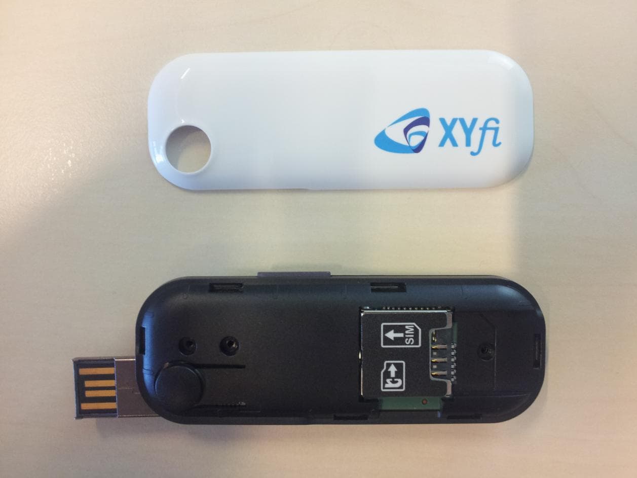
Click to zoom
Application Details
- Equipment Class
- JBP - Part 15 Class B Computing Device Peripheral
- Date of Grant
- Dec 22, 2011
- Application Purpose
- Original Equipment
- Date of Application
- Dec 20, 2011
- Equipment Note
- Quadband GSM/GPRS/EDGE Triband UMTS/HSDPA/HSUPA USB Modem
- Company
- Option (Crescent NV)
- Country
- Belgium
Documents & Files
Document Text
Text extracted from the exhibit documents filed with the FCC. Open a document above to read the original.
Users Manual
Safety & Certification Leaflet Page: 1 of 4 Option ® Copyright: This document may not be duplicated, nor distributed to third parties without prior and written permission of Option ® nv. GI0643 FCC ID NCMOGI0643 Safety & Certification Leaflet Your iCON XYfi is like a mobile phone Your iCON XYfi uses the same technology as a mobile phone. It is important that you always obey all safety regulations related to mobile phone use. If you have any doubt about the safe operation of your iCON XYfi you should remove the iCON XYfi from the PC and seek advice from authorized personnel. Handle with care This device is designed to be plugged directly into the USB port of a computer, however, every precaution should be taken to avoid stress on the device should the computer be lifted, moved, relocated or packaged. Should regular movement of this nature be envisaged, an extender cable (sometimes supplied with the device) should be used so as to avoid damage to the device. It should be noted that any damage sustained as a result of the aforementioned mishandling will be regarded as “User Damage” and shall render the product warranty null and void 1. Safety Measurements Please read the following guidelines carefully. Not following these guidelines can cause harm to the USB stick, yourself or other persons. 1.1 General recommendations for use Always treat your product with care and keep in a clean and dust-free place. Do not expose your product to open flames or lit tobacco products. Do not expose to liquid, moisture or humidity. Do not expose the iCON XYfi to rain or other liquids. Do not drop, throw or try to bend your product. Do not paint your product. Do not attempt to disassemble your product. Doing so may be dangerous and it will void the warranty. Do not touch the antenna unnecessarily. (This is located either inside the product or as an external antenna.) 1.2 Traveling: Handle the USB stick with care while traveling. It is recommended to remove the USB stick from the laptop. 1.3 Ambient temperatures: Do not expose the iCON XYfi or the antenna to ambient temperatures beyond the range of 0 and +40 degrees Celsius. 1.4 Explosive atmosphere: Turn off your PC in any area with a potentially explosive atmosphere. It is rare, but your PC could generate sparks, which could cause an explosion or fire. Areas with a potentially explosive atmosphere are not always clearly marked. They include fuelling areas (petrol filling stations), below deck on boats, fuel or chemical transfer or storage facilities and areas where the air contains chemicals or particles, such as grain, dust, or metal powders. Do not transport or store your PC and accessories in the compartment of a vehicle which contains flammable gas, liquid or explosives. 1.5 Blasting areas – construction sites: Turn off your PC when in a blasting area in order to avoid interfering with two-way radios used in blasting operations. 1.6 Do not use on aircraft: Using a wireless devices on aircraft can cause interference and is illegal. Remove your iCON XYfi if you intend to use your PC whilst in an aircraft. Do not use it when the plane is on the ground without permission from the aircraft crew. 1.7 Do not use in hospitals: Please ensure you follow any local regulations or rules. People are often asked to switch off all electronic devices in some areas of a hospital. This is a recommendation that Option ® fully supports. Using the iCON XYfi close to sensitive electronic devices could possibly result in interference. If you intend to use your PC in such areas, you must remove the iCON XYfi. Safety & Certification Leaflet Page: 2 of 4 Option ® Copyright: This document may not be duplicated, nor distributed to third parties without prior and written permission of Option ® nv. 1.8 Interference from radio signals: Option ® relies on advice from health authorities and relevant expert bodies about potentially undesirable reactions to radio emissions from the iCON XYfi. 1.9 Immunity to interference: Electromagnetic interference is the disturbance of the normal operation of a device due to its response to radio signals from an external source. Occasionally, in some situations you may hear short sounds coming from audio equipment such as radio or multimedia PC. However, these audible signals do not interfere with the operation of the equipment. The Directive from the European Commission (2004/108/EC) governing all forms of electronic equipment concerns interference that such equipment produces, and its immunity to interference from outside. Any equipment compliant with that directive is unlikely to suffer interference. All wireless devices may get interference which could affect performance. 1.10 Cardiac pacemakers, implanted defibrillators & other medical implant devices It is possible that the iCON XYfi may interfere with some types of pacemakers or implanted defibrillators when operated close to the implanted device. You should seek advice from your doctor that is specific to the implant before using the iCON XYfi. Health authorities in many countries have set up advisory services for medical devices and implants including providing advice about maintaining separation distance between the mobile device or other radio frequency equipment and the implant. Option ® operating companies reflect the advice given by their relevant health authority or national advisory service, and as a minimum recommend a separation distance of at least 20 cm between the iCON XYfi or other radio frequency terminal equipment and the embedded device. 1.11 Hearing devices: People with hearing aids or other cochlear implants may experience interfering noises when using mobile devices or when one is nearby. The level of interference will depend on the type of mobile device, the type of hearing device and the distance between the two. Increasing the distance between the iCON XYfi and hearing device may reduce interference. 1.12 Children: Do not allow children to play with your iCON X…
Text truncated - open the document above for the full version.
Users Manual
HomeSite MapSupport and HelpLog Out SettingsSMS User GuideFAQUseful LinksTroubleshootingContact us HomeSupport and HelpUser Guide User Guide Do you need information about how to configure the iCON XYfi, or how to change your WiFi password? Or do you want to know how to set up the access mode? You will find it all in the User Guide! Quick Start Home Settings SMS LED Languages Web Browser Requirements Safety and Certification 1. Quick Start Welcome to the iCON XYfi user guide pages! In this chapter we have summarised the most important information in order to get you started more quickly. A detailed overview of each function of the iCON XYfi can be obtained in the other chapters of this documentation. Insert SIM Card User Guide FAQ Useful Links Troubleshooting Contact us English English Back To Top Power Up iCON XYfi Connect to Internet Connect to Administration Pages 1.1 Insert SIM Card Before connecting the iCON XYfi to you PC/tablet/smartphone etc. for the first time, you must insert the SIM card supplied by your service provider: 1) Remove the top cover of the iCON XYfi. 2) Insert the SIM card and the optional micro-SD card into the corresponding card slots. 3) Put the top cover back on by inserting it into the slot at the front and press the cover down until it clicks into place. 1.2 Power Up iCON XYfi For iCON XYfi to be able to connect to any Mobile or WiFi networks, it needs to be switched on. Before you connect it to a power source, you need to fully extend the unique USB connector (180 degrees) by pushing the button on the top of the iCON XYfi. iCON XYfi can use several different power sources: Computer: Insert the iCON XYfi into a free USB port on your computer. USB Power Adapter: Switch on the iCON XYfi via the 110-240v power socket. USB Cigarette Lighter Adapter: Use your iCON XYfi in cars/boats/buses etc. or other places where you have a 12V cigarette lighter socket. USB Battery Pack: When travelling, this is the ideal way to power the iCON XYfi. Others: Such as Car Stereo, Playstation, Wii etc. (with USB connection)...Please make sure that it offers min. 5V/1 Amp output power. Note: You should only use the original USB Power Adapter/Cigarette Lighter Adapter and USB Battery Pack as replacement power sources may damage your iCON XYfi and make it less reliable. Option NV is not responsible for damage caused by using non-Option NV products. 1.3 Connect to Internet iCON XYfi comes with pre-defined settings that makes it very easy for you to connect to the Internet: 1) Your iCON XYfi is pre-configured with WPA2 encryption to protect unauthorised access. The unique Network Name (SSID) and WiFi Password (Pre-shared key) are printed on the manufacturing label underneath the bottom cover. 2) When your iCON XYfi is switched on, find the Network Name (SSID) in your list of available networks and click Connect. 3) You will be asked to fill in the WiFi password, and when this is done, you are connected to the Internet. If your PIN code is not disabled, or if it is not a known APN address, you will be guided to the settings pages to make the changes before being able to connect to the Internet. International roaming is disabled by default, and if you use the iCON XYfi for the first time in this situation, you need to enable roaming within the settings pages. 1.4 Connect to Administration Pages The administration pages give you access to see/edit all the settings for the iCON XYfi, in addition to the connection status etc. In order to log in to the administration pages (valid both for desktop and mobile version): 1a) Desktop: Open your Internet browser and type XYfi/ in the address bar (or 172.22.2.1) and press 'Enter'. 1b) Mobile (smartphone): Open your Internet browser and type XYfi/ in the address bar. If 'XYfi/' does not send you to the mobile site, type m.XYfi/ (or 172.22.2.1) and press 'Go'. 2) The Log In page will open and you have to create/insert your username and password (case sensitive) to enter the administration pages. You can save this address as a bookmark in your browser or add to your home screen, for future use. 2. Home This is your iCON XYfi homepage where you can carry out basic connection settings. Connect Button Status Bar Connect a device to iCON XYfi using Wi-Fi Protected Setup Manage Users and your iCON XYfi Index Index Index Index Back To Top 2.1 Connect Button Establish or terminate the connection (soft button). You can also establish or terminate the connection (physically), by pushing the LED button for 1 second. 2.2 Status Bar The Status Bar gives you an easy access and a quick overview of your current connection. Network Provider Technology Signal Strength Speed (Mbps) Active Users Current Access Mode 2.2.1 Network Provider The company that provides access to the Internet. If the icons colour changes to violet (normally blue), it means you are in roaming mode using mobile network connection 2.2.2 Technology This indicates whether your iCON XYfi is currently connected to a WiFi or Mobile Network. If you are connected to a mobile network, it will also indicate if you have a 3G (HSPA) or a (slower) 2G (EDGE/GPRS) connection. 2.2.3 Signal Strength To help you position the iCON XYfi for best reception of the Mobile Network signal, we have included a signal strength monitor mode on the front page. The signal strengths indicators move up as the strength of the signal increases and down as the signal decreases (only shown if you are registered to a network). To increase the signal strength of your iCON XYfi , try moving it slightly, or move towards a window if you are Index Index Index Index Index Automatically add WiFi devices to your iCON XYfi using WPS - 'WiFi Protected Set-up'. Your device needs to support WPS in order to use this feature. connecting from inside a building. If you continuously experience low signal strength in a certain area, it may be that network coverage is insufficient there. Your operator or service provider can provide you with more inform…
Text truncated - open the document above for the full version.
Test Report
Final Report on GI0643 MDE_OPTI_1101_FCCc acc. Title 47 CFR chapter I part 15 subpart B Report Reference: Se ptember 30, 2011Date: Test Laboratory: 7Layers AG Borsigstr. 11 40880 Ratingen Germany Note: The following test results relate only to the devices specified in this document. This report shall not be reproduced in parts without the written approval of the test laboratory. 7Lay ers A G A ufsichtsrat sv orsit ze nde r h Registergerichth registered in: B orsigst ra sse 11 Chairma n of t he Supervisory Board: Düsseldorf, HRB 44096 40880 Ratingen, Germany Markus Becker USt-IdNr h VAT No.: Phone: +49 (0) 2102 749 0 Vorstandh Board: DE 203159652 Fax: +49 (0) 2102 749 350 Dr. H.-J. Meckelburg TAX No. 147/5869/0385 www.7Layers.com Reference: MDE_OPTI_1101_FCCc acc. Title 47 CFR chapter I part 15 subpart B 1Administrative Data 1.1Project Data Yao JingPro ject Responsible: 2011/09/30Date Of Test Re port: 2011/07/18Date of first test: 2011/08/08Date of last test: 1.2Applicant Data Company Name:Option nv Gaston Geenslaan 14,Street: B-3001 Leuven City: BelgiumCountry: Contact Person:Mr. Jan Willems +32 16 311 516Phone: [email protected]: 1.3Test Laboratory Data The following list shows all places and laboratories involved for test result generation: 7 layers DE Company Name :7 layers AG Street :Borsigstrasse 11 City :40880 Ratingen Country :Germany Contact Person :Mr. Michael Albert Phone :+49 2102 749 201 Fax :+49 2102 749 444 E Mail :[email protected] Laboratory Details Accreditation InfoLab IDIdentificationResponsible DAkkS-Registration no. D-PL-12140-01-01Conducted EmissionsLab 1Mr. Robert Machulec Mr. Andreas Petz DAkkS-Registration no. D-PL-12140-01-01Radiated EmissionsLab 2Mr. Robert Machulec Mr. Andreas Petz Page 2 of 24 Reference: MDE_OPTI_1101_FCCc acc. Title 47 CFR chapter I part 15 subpart B 2.2Detailed Description of OUT Samples Sample : b01 OUT IdentifierGI0643 Sample DescriptionUSB modem Serial No.YM29B2B548 HW Status2.0.2.0 SW Status2.1.1.0x Date of Receipt2011/06/20 Nominal Voltage5 V 2.3OUT Features Features for OUT: GI0643 Allowed ValuesDesignationDescriptionSupported Value(s) Features for scope: FCC_v2 DCThe OUT is powered by or connected to DC Mains EDGE850EUT supports EDGE in the band 824 MHz - 849 MHz EDGE1900EUT supports EDGE in the band 1850 MHz - 1910 MHz FDD2EUT supports UMTS FDD2 in the band 1850 MHz - 1910 MHz GSM850EUT supports GSM850 band 824MHz - 849MHz HSDPA- FDD2 EUT supports UMTS FDD2 HSDPA in the band 1850 MHz - 1910 MHz HSUPA- FDD2 EUT supports UMTS FDD2 HSUPA in the band 1850 MHz - 1910 MHz IantIntegral Antenna: permanent fixed antenna, which may be built-in, designed as an indispensable part of the equipment PantCpermanent fixed antenna connector, which may be built-in, designed as an indispensable part of the equipment PCS1900EUT supports PCS1900 band 1850MHz - 1910MHz WbEUT supports WLAN in mode b in the band 2400 MHz - 2483.5 MHz WgEUT supports WLAN in mode g in the band 2400 MHz - 2483.5 MHz WnEUT supports WLAN in mode n in the band 2400 MHz - 2483.5 MHz Page 4 of 24 Reference: MDE_OPTI_1101_FCCc acc. Title 47 CFR chapter I part 15 subpart B 2.4Auxiliary Equipment AE No.Serial No.SW StatusHW StatusDescriptionType Designation AE 6Cherry RS 6000 USB ON G 0000273 2P28 --Keyboard AE 2LG Flatron L1740BQ509WANF1W607 FCC ID: BEJL17NU -TFT AE 5Logitech M-BB48LZC90505478--Mouse AE 1Medion MD 83053MSN: 5003 7805 06/27/11-AC/DC USB travel adapter AE 4Toshiba PA3378E- 3AC3 ---AC Adapter AE 3Toshiba TECRA M987060248H--Laptop 2.5Operating Mode(s) Ref.-No.Description 1GSM850 TCH190 (836.6MHz), WLAN active, powered by AE 3 at 120 V AC 2GSM1900 TCH661 (1880.0MHz), WLAN active, powered by AE 3 at 120 V AC 3GSM850 TCH190 (836.6MHz), WLAN active, powered by AE 1 at 120 V AC 2.6Setups used for Testing For each setup a relation is given to determine if and which samples and auxiliary equipment is used. The left side list all OUT samples and the right side lists all auxiliary equipment for the given setup. Sample No.Sample DescriptionAE No.AE Description Setup No.List of OUT samplesList of auxiliary equipment S01_B01_ACDC AE 1AC/DC USB travel adapterb01USB modemSample: S01_B01_Comp AE 6Keyboardb01USB modemSample: AE 2TFT AE 5Mouse AE 4AC Adapter AE 3Laptop Page 5 of 24 Reference: MDE_OPTI_1101_FCCc acc. Title 47 CFR chapter I part 15 subpart B 3Results 3.1General Available at the test laboratory. The results of the inspection are described on the following pages, where 'Conformity' or 'Passed' means that the certification criteria were verified and that the tested device is conform to the applied standard. In cases where 'Declaration' is printed, the required documents are available in the manufacturers product documentation. In cases where 'not applicable' is printed, the test case requirements are not relevant to the specific equipment implementation. Documentation of tested devices: Interpretation of the test results: 3.2List of the Applicable Body (Body for Scope: FCC_v2) DesignationDescription Part 15, Subpart B - Unintentional RadiatorsFCC47CFRChIPART15bRADIO FREQUENCY DEVICES 3.3List of Test Specification Test Specification:FCC part 2 and 15 Version10-1-10 Edition Title:PART 2 - GENERAL RULES AND REGULATIONS PART 15 - RADIO FREQUENCY DEVICES Page 6 of 24 Reference: MDE_OPTI_1101_FCCc acc. Title 47 CFR chapter I part 15 subpart B 3.4Summary Test Case Identifier / Name SetupDate of TestResultTest (condition)Ref. Lab 15b.1 Conducted Emissions (AC Power Line) §15.107 15b.1; Mode = transmit2011/08/08S01_B01_ACDCLab 1Passed operating mode: 3 2011/08/08S01_B01_CompLab 1Passed operating mode: 1 15b.2 Spurious Radiated Emissions §15.109 15b.2; Mode = transmit2011/07/18S01_B01_CompLab 2Passed operating mode: 2 Page 7 of 24 Reference: MDE_OPTI_1101_FCCc acc. Title 47 CFR chapter I part 15 subpart B 3.5Detailed Results 3.5.115b.1 Conducted Emissions (AC Power Line) §15.107 Test1: 15b.1; Mode = transmit Result:Passed Setup No.:S01_B01_Comp Date of Test:2011/08/08 …
Text truncated - open the document above for the full version.
Test Setup Photos
Test Laboratory: Borsigstr. 11 Germany 7Layers AG 40880 Ratingen Note: The following test results relate only to the devices specified in this document. This report shall not be reproduced in parts without the written approval of the test laboratory. 7Layers AG Aufsichtsratsvorsitzender h Registergerichth registered in: Borsigstrasse 11 Chairman of the Supervisory Board: Düsseldorf, HRB 44096 40880 Ratingen, Germany Markus Becker USt-IdNr h VAT No.: Phone: +49 (0) 2102 749 0 Vorstandh Board: DE 203159652 Fax: +49 (0) 2102 749 350 Dr. H.-J. Meckelburg TAX No. 147/5869/0385 www.7Layers.com Photo Report GI0643 Report Reference: MDE_OPTI_1101_FCC_Photo Test report Reference: MDE_OPTI_1101_FCC_Photo Page 2 of 8 1 Photo Report 1.1 Photos of test setups Photo 1: Test setup for radiated measurements (Enclosure, below 30 MHz) Photo 2: Test setup for radiated measurements (Enclosure, 30 MHz to 1 GHz) Test report Reference: MDE_OPTI_1101_FCC_Photo Page 3 of 8 Photo 3: Test setup for radiated measurements (Enclosure, above 1 GHz) Photo 4: Test setup for radiated measurements (Enclosure, radiated output power measurement) Test report Reference: MDE_OPTI_1101_FCC_Photo Page 4 of 8 Photo 5: Test setup for radiated measurements (emission measurement using computer periphery setup) Photo 6: Test setup for conducted measurements (AC Port (power line) using computer periphery setup) Test report Reference: MDE_OPTI_1101_FCC_Photo Page 5 of 8 Photo 7: Test setup for conducted measurements (AC Port (power line)) Test report Reference: MDE_OPTI_1101_FCC_Photo Page 6 of 8 1.2 Photos of the EUT Photo 8: EUT (top side) Photo 9: EUT (bottom side) Test report Reference: MDE_OPTI_1101_FCC_Photo Page 7 of 8 Photo 10: EUT (right side) Photo 11: EUT (left side) Test report Reference: MDE_OPTI_1101_FCC_Photo Page 8 of 8 Photo 12: EUT (open enclosure top side) Photo 13: EUT (open enclosure bottom side)
Contact Information
Applicant
Joost van der Velden(CEO)
Test Firm
7layers AGRobert Machulec
Technical Specifications
| # | Rule Parts | Frequency Range | Power Output |
|---|---|---|---|
| 1 | 15B | - | - |
Other Applications from Option (Crescent NV)

NCM-CG2132
Sep 21, 2022LoRaWAN 86x/9xx Expansion card
Equipment Class
DTS - Digital Transmission System
NCM-WT500
Jun 06, 2021Water and Temperature Sensor
Equipment Class
DSS - Part 15 Spread Spectrum Transmitter
NCMOCG2101
Feb 27, 2013CloudGate 802.11abgn Wireless LAN Card
Equipment Class
NII - Unlicensed National Information Infrastructure TX
NCMOMO6792
Feb 24, 2013GTM679W
Equipment Class
JBP - Part 15 Class B Computing Device PeripheralNCMOGI0644
Jun 17, 2012GSM/UMTS/WLAN USB Modem GI0644
Equipment Class
PCB - PCS Licensed Transmitter