NCMOGI0644GSM/UMTS/WLAN USB Modem GI0644
Option (Crescent NV)Application Details
- Equipment Class
- PCB - PCS Licensed Transmitter
- Date of Grant
- Jun 17, 2012
- Application Purpose
- Original Equipment
- Date of Application
- May 21, 2012
- Equipment Note
- GSM/UMTS/WLAN USB Modem GI0644
- Frequency Range
- 1852.40000000 - 1907.60000000
- Company
- Option (Crescent NV)
- Country
- Belgium
Documents & Files
Document Text
Text extracted from the exhibit documents filed with the FCC. Open a document above to read the original.
Users Manual
HomeSite MapSupport and HelpLog Out SettingsSMS User GuideFAQUseful LinksTroubleshootingContact us HomeSupport and HelpUser Guide User Guide Do you need information about how to configure the iCON XYfi, or how to change your WiFi password? Or do you want to know how to set up the access mode? You will find it all in the User Guide! Quick Start Home Settings SMS LED Languages Web Browser Requirements Safety and Certification 1. Quick Start Welcome to the iCON XYfi user guide pages! In this chapter we have summarised the most important information in order to get you started more quickly. A detailed overview of each function of the iCON XYfi can be obtained in the other chapters of this documentation. Insert SIM Card User Guide FAQ Useful Links Troubleshooting Contact us English English Back To Top Power Up iCON XYfi Connect to Internet Connect to Administration Pages 1.1 Insert SIM Card Before connecting the iCON XYfi to you PC/tablet/smartphone etc. for the first time, you must insert the SIM card supplied by your service provider: 1) Remove the top cover of the iCON XYfi. 2) Insert the SIM card and the optional micro-SD card into the corresponding card slots. 3) Put the top cover back on by inserting it into the slot at the front and press the cover down until it clicks into place. 1.2 Power Up iCON XYfi For iCON XYfi to be able to connect to any Mobile or WiFi networks, it needs to be switched on. Before you connect it to a power source, you need to fully extend the unique USB connector (180 degrees) by pushing the button on the top of the iCON XYfi. iCON XYfi can use several different power sources: Computer: Insert the iCON XYfi into a free USB port on your computer. USB Power Adapter: Switch on the iCON XYfi via the 110-240v power socket. USB Cigarette Lighter Adapter: Use your iCON XYfi in cars/boats/buses etc. or other places where you have a 12V cigarette lighter socket. USB Battery Pack: When travelling, this is the ideal way to power the iCON XYfi. Others: Such as Car Stereo, Playstation, Wii etc. (with USB connection)...Please make sure that it offers min. 5V/1 Amp output power. Note: You should only use the original USB Power Adapter/Cigarette Lighter Adapter and USB Battery Pack as replacement power sources may damage your iCON XYfi and make it less reliable. Option NV is not responsible for damage caused by using non-Option NV products. 1.3 Connect to Internet iCON XYfi comes with pre-defined settings that makes it very easy for you to connect to the Internet: 1) Your iCON XYfi is pre-configured with WPA2 encryption to protect unauthorised access. The unique Network Name (SSID) and WiFi Password (Pre-shared key) are printed on the manufacturing label underneath the bottom cover. 2) When your iCON XYfi is switched on, find the Network Name (SSID) in your list of available networks and click Connect. 3) You will be asked to fill in the WiFi password, and when this is done, you are connected to the Internet. If your PIN code is not disabled, or if it is not a known APN address, you will be guided to the settings pages to make the changes before being able to connect to the Internet. International roaming is disabled by default, and if you use the iCON XYfi for the first time in this situation, you need to enable roaming within the settings pages. 1.4 Connect to Administration Pages The administration pages give you access to see/edit all the settings for the iCON XYfi, in addition to the connection status etc. In order to log in to the administration pages (valid both for desktop and mobile version): 1a) Desktop: Open your Internet browser and type XYfi/ in the address bar (or 172.22.2.1) and press 'Enter'. 1b) Mobile (smartphone): Open your Internet browser and type XYfi/ in the address bar. If 'XYfi/' does not send you to the mobile site, type m.XYfi/ (or 172.22.2.1) and press 'Go'. 2) The Log In page will open and you have to create/insert your username and password (case sensitive) to enter the administration pages. You can save this address as a bookmark in your browser or add to your home screen, for future use. 2. Home This is your iCON XYfi homepage where you can carry out basic connection settings. Connect Button Status Bar Connect a device to iCON XYfi using Wi-Fi Protected Setup Manage Users and your iCON XYfi Index Index Index Index Back To Top 2.1 Connect Button Establish or terminate the connection (soft button). You can also establish or terminate the connection (physically), by pushing the LED button for 1 second. 2.2 Status Bar The Status Bar gives you an easy access and a quick overview of your current connection. Network Provider Technology Signal Strength Speed (Mbps) Active Users Current Access Mode 2.2.1 Network Provider The company that provides access to the Internet. If the icons colour changes to violet (normally blue), it means you are in roaming mode using mobile network connection 2.2.2 Technology This indicates whether your iCON XYfi is currently connected to a WiFi or Mobile Network. If you are connected to a mobile network, it will also indicate if you have a 3G (HSPA) or a (slower) 2G (EDGE/GPRS) connection. 2.2.3 Signal Strength To help you position the iCON XYfi for best reception of the Mobile Network signal, we have included a signal strength monitor mode on the front page. The signal strengths indicators move up as the strength of the signal increases and down as the signal decreases (only shown if you are registered to a network). To increase the signal strength of your iCON XYfi , try moving it slightly, or move towards a window if you are Index Index Index Index Index Automatically add WiFi devices to your iCON XYfi using WPS - 'WiFi Protected Set-up'. Your device needs to support WPS in order to use this feature. connecting from inside a building. If you continuously experience low signal strength in a certain area, it may be that network coverage is insufficient there. Your operator or service provider can provide you with more inform…
Text truncated - open the document above for the full version.
ID Label/Location Info
Option nv sa | Gaston Geenslaan 14 | B-3001 Leuven Belgium | www.option.com T +32 16 317 411 | F +32 16 207 164 | H.R.L./R.C.L. 68114 | BTW/TVA BE 429.375.448 Label Information Label Information for ‘GI0644’, FCC ID NCMOGI0644
RF Exposure Info
The Testcenter facility ‘Dosimetric Test Lab’ within IMST GmbH is accredited by the German National ‘Deutsche Akkreditierungsstelle GmbH (DAkkS)’ for testing according to the scope as listed in the accreditation certificate: D-PL-12139-01-01. SAR_Report_7layers_60320_6120061_FCC_Body_850_1900_FDD2_5_802.11_GI0644 Page 1 of 44 Report Dosimetric Assessment of the Portable Device GI0644 from Option tested in one Host Product (FCC ID: NCMOGI0644) According to the FCC Requirements March 08, 2012 IMST GmbH Carl-Friedrich-Gauß-Str. 2 D-47475 Kamp-Lintfort Customer 7layers AG Borsigstrasse 11 D-40880 Ratingen The test results only relate to the items tested. This report shall not be reproduced except in full without the written approval of the testing laboratory. Dasy_Report_ FCC_Body_Card_850_1900_WCDMA II_WCDMA V_1.4.doc/20.06.2008/ABo SAR_Report_7layers_60320_6120061_FCC_Body_850_1900_FDD2_5_802.11_GI0644 Page 2 of 44 Dasy_Report_ FCC_Body_Card_850_1900_WCDMA II_WCDMA V_1.4.doc/20.06.2008/ABo Executive Summary The device GI0644 is a new USB stick from Option operating in the 850 MHz, 900 MHz, 1800 MHz, 1900 MHz and 2450 MHz frequency range. The device has two integrated antennas and the system concepts used are the GPRS/EDGE 850, GPRS/EDGE 900, GPRS/EDGE 1800, GPRS/EDGE 1900, WCDMA I (FDD), WCDMA II (FDD), WCDMA V (FDD) and IEEE 802.11 b/g/n standards. The USB stick provides HSDPA and HSUPA in WCDMA. In simultaneous transmission mode a WLAN and WWAN connection could be active at the same time. The objective of the measurements done by IMST was the dosimetric assessment of one device in body worn configuration in the WCDMA V (FDD) standard. Following the manufacturer, the USB dongle XYfi from Option, assessed in “SAR_Report_7layers_6620_858_FCC_Body_850_1900_WCDMAII_802.11_XYfi_3” [IMST SAR], is technical identical with the GI0644. Therefore for the GI0644 in the GPRS 850 (Class 11), GPRS 1900 (Class 12), WCDMA II (FDD) and IEEE 802.11 b standards, SAR assessment was conducted only for the worst case configuration shown in above mentioned SAR report. The measurements were performed in combination with one host product (Dell Latitude X300). According to Fig. 2 the device was tested in six positions in 180° configurations with a maximum distance of 5 mm between DUT and phantom. Since the device is equipped with a swivel antenna which can be used in 180° and 90° angel, additional measurements in worst case configuration for the 90° mode has been conducted. The examinations have been carried out with the dosimetric assessment system „DASY4“. The measurements were made according to the Supplement C to OET Bulletin 65 of the Federal Communications Commission (FCC) Guidelines [OET 65] for evaluating compliance of mobile and portable devices with FCC limits for human exposure (general population) to radiofrequency emissions. Additional information and guidelines given by the following FCC documents were used: SAR Measurement Procedures for 3G Devices [KDB 941225] Mobile and Portable Devices RF Exposure Procedures and Equipment Authorization Policies [KDB 447498] SAR Measurement Procedure for 802.11 a/b/g Transmitter [KDB 248227] SAR Evaluation Considerations for Handsets with Multiple Transmitter and Antennas [KDB 648474] All measurements have been performed in accordance to the recommendations given by SPEAG. SAR_Report_7layers_60320_6120061_FCC_Body_850_1900_FDD2_5_802.11_GI0644 Page 3 of 44 Dasy_Report_ FCC_Body_Card_850_1900_WCDMA II_WCDMA V_1.4.doc/20.06.2008/ABo For the USB dongle XYfi from Option a PBA was send to the authorities. According to the FCC reply, the USB stick was tested in the following configurations: According to Fig. 2 the device was tested in six positions in 180° configuration for WCDMA V (FD) with a maximum distance of 5 mm between DUT and phantom. In addition, body SAR was also measured in HSDPA using Subtest 1 and HSUPA using Subtest 5 at the highest body SAR configuration without HSDPA and HSUPA. GPRS/EDGE 850 (Class 11), GPRS/EDGE 1900 (Class 12) and WCDMA II (FDD) was assessed in worst case configuration according to “SAR_Report_7layers_ 6620_858_FCC_Body_850_1900_WCDMAII_802.11_XYfi_3” [IMST SAR]. The device was tested with one host product (Dell Latitude X300). According the output power measurements, for GPRS 850 Class 11 and GPRS 1900 Class 12 delivers the highest output power. Therefore the SAR tests are conducted in GPRS Class 11 for GPRS/EDGE 850 and Class 12 for GPRS/EDGE 1900. Additionally, “bottom tip” (position 6) and the position that delivers the highest SAR value was assessed in 90° configuration. prepared by: ......................................... reviewed by: ......................................... Alexander Rahn André van den Bosch test engineer quality assurance engineer SAR_Report_7layers_60320_6120061_FCC_Body_850_1900_FDD2_5_802.11_GI0644 Page 4 of 44 Dasy_Report_ FCC_Body_Card_850_1900_WCDMA II_WCDMA V_1.4.doc/20.06.2008/ABo Table of Contents 1 SUBJECT OF INVESTIGATION .................................................................................................................... 5 2 THE IEEE STANDARD C95.1 AND THE FCC EXPOSURE CRITERIA ................................................. 5 2.1 DISTINCTION BETWEEN EXPOSED POPULATION, DURATION OF EXPOSURE AND FREQUENCIES ........... 6 2.2 DISTINCTION BETWEEN MAXIMUM PERMISSIBLE EXPOSURE AND SAR LIMITS ....................................... 6 2.3 GENERAL SAR LIMIT ................................................................................................................................. 7 2.4 KDB 447498 SAR LIMIT ........................................................................................................................... 7 3 THE FCC MEASUREMENT PROCEDURE ................................................................................................. 7 3.1 GENERAL REQUIREMENTS.............................................................................................…
Text truncated - open the document above for the full version.
RF Exposure Info
The Testcenter facility ‘Dosimetric Test Lab’ within IMST GmbH is accredited by the German National ‘Deutsche Akkreditierungsstelle GmbH (DAkkS)’ for testing according to the scope as listed in the accreditation certificate: D-PL-12139-01-01. SAR_Report_7layers_60320_6120061_FCC_Body_850_1900_II_V_802.11_Plots_GI0644 Page 1 of 20 Appendix for the Report Dosimetric Assessment of the Portable Device GI0644 from Option tested in one host product (FCC ID: NCMOGI0644) According to the FCC Requirements SAR Distribution Plots March 08, 2012 IMST GmbH Carl-Friedrich-Gauß-Str. 2 D-47475 Kamp-Lintfort Customer 7layers AG Borsigstrasse 11 D-40880 Ratingen The test results only relate to the items tested. This report shall not be reproduced except in full without the written approval of the testing laboratory. dasy_report_fcc_850_1900_plots_1.1.doc/04.07.2005/CH SAR_Report_7layers_60320_6120061_FCC_Body_850_1900_II_V_802.11_Plots_GI0644 Page 2 of 20 dasy_report_fcc_850_1900_plots_1.1.doc/04.07.2005/CH Table of Contents 1 SAR DISTRIBUTION PLOTS, WCDMA V BODY ............................................................................... 3 2 SAR DISTRIBUTION PLOTS, WORST CASE GPRS 850 BODY .................................................... 12 3 SAR DISTRIBUTION PLOTS, WORST CASE GPRS 1900 BODY .................................................. 13 4 SAR DISTRIBUTION PLOTS, WORST CASE WCDMA FDD II BODY ............................................ 14 5 SAR DISTRIBUTION PLOTS, WORST CASE IEEE 802.11B BODY ............................................... 16 6 SAR Z-AXIS SCANS (VALIDATION) ................................................................................................ 17 7 SAR Z-AXIS SCANS (MEASUREMENTS) ........................................................................................ 18 SAR_Report_7layers_60320_6120061_FCC_Body_850_1900_II_V_802.11_Plots_GI0644 Page 3 of 20 dasy_report_fcc_850_1900_plots_1.1.doc/04.07.2005/CH 1 SAR Distribution Plots, WCDMA V Body Test Laboratory: IMST GmbH, DASY Blue (I); File Name: 679_buhm_1_5mm.da4 DUT: Option; Type: GI0644; Serial: 004401441450679 Program Name: WCDMA V Communication System: WCDMA (FDD) Band V; Frequency: 836.5 MHz;Duty Cycle: 1:1 Medium parameters used: f = 836.6 MHz; σ = 0.99 mho/m; ε r = 53.4; ρ = 1000 kg/m 3 Phantom section: Flat Section DASY4 Configuration: - Probe: ET3DV6R - SN1579; ConvF(6.24, 6.24, 6.24); Calibrated: 25.01.2012 - Sensor-Surface: 4mm (Mechanical Surface Detection) - Electronics: DAE3 Sn335; Calibrated: 20.02.2012 - Phantom: SAM Sugar 1059; Type: Speag; Serial: 1059 - Measurement SW: DASY4, V4.7 Build 80; Postprocessing SW: SEMCAD, V1.8 Build 186 Body Worn/Area Scan (7x10x1): Measurement grid: dx=15mm, dy=15mm Maximum value of SAR (measured) = 0.524 mW/g Body Worn/Zoom Scan (7x7x7)/Cube 0: Measurement grid: dx=5mm, dy=5mm, dz=5mm Reference Value = 23.0 V/m; Power Drift = -0.055 dB Peak SAR (extrapolated) = 0.759 W/kg SAR(1 g) = 0.487 mW/g; SAR(10 g) = 0.304 mW/g Maximum value of SAR (measured) = 0.529 mW/g Fig. 1: SAR distribution for WCDMA V, channel 4183, Position 1 (Dell Latitude X300, March 01, 2012; Ambient Temperature: 22.4°C; Liquid Temperature: 22.1°C). Laptop Area DUT Area SAR_Report_7layers_60320_6120061_FCC_Body_850_1900_II_V_802.11_Plots_GI0644 Page 4 of 20 dasy_report_fcc_850_1900_plots_1.1.doc/04.07.2005/CH Test Laboratory: IMST GmbH, DASY Blue (I); File Name: 679_buhm_2_5mm.da4 DUT: Option; Type: GI0644; Serial: 004401441450679 Program Name: WCDMA V Communication System: WCDMA (FDD) Band V; Frequency: 836.5 MHz;Duty Cycle: 1:1 Medium parameters used: f = 836.6 MHz; σ = 0.99 mho/m; ε r = 53.4; ρ = 1000 kg/m 3 Phantom section: Flat Section DASY4 Configuration: - Probe: ET3DV6R - SN1579; ConvF(6.24, 6.24, 6.24); Calibrated: 25.01.2012 - Sensor-Surface: 4mm (Mechanical Surface Detection) - Electronics: DAE3 Sn335; Calibrated: 20.02.2012 - Phantom: SAM Sugar 1059; Type: Speag; Serial: 1059 - Measurement SW: DASY4, V4.7 Build 80; Postprocessing SW: SEMCAD, V1.8 Build 186 Body Worn/Area Scan (7x10x1): Measurement grid: dx=15mm, dy=15mm Maximum value of SAR (measured) = 0.577 mW/g Body Worn/Zoom Scan (7x7x7)/Cube 0: Measurement grid: dx=5mm, dy=5mm, dz=5mm Reference Value = 23.8 V/m; Power Drift = -0.126 dB Peak SAR (extrapolated) = 0.822 W/kg SAR(1 g) = 0.528 mW/g; SAR(10 g) = 0.328 mW/g Maximum value of SAR (measured) = 0.575 mW/g Fig. 2: SAR distribution for WCDMA V, channel 4183, Position 2 (Dell Latitude X300, March 01, 2012; Ambient Temperature: 22.4°C; Liquid Temperature: 22.1°C). Laptop Area DUT Area SAR_Report_7layers_60320_6120061_FCC_Body_850_1900_II_V_802.11_Plots_GI0644 Page 5 of 20 dasy_report_fcc_850_1900_plots_1.1.doc/04.07.2005/CH Test Laboratory: IMST GmbH, DASY Blue (I); File Name: 679_buhm_3_5mm.da4 DUT: Option; Type: GI0644; Serial: 004401441450679 Program Name: WCDMA V Communication System: WCDMA (FDD) Band V; Frequency: 836.5 MHz;Duty Cycle: 1:1 Medium parameters used: f = 836.6 MHz; σ = 0.99 mho/m; ε r = 53.4; ρ = 1000 kg/m 3 Phantom section: Flat Section DASY4 Configuration: - Probe: ET3DV6R - SN1579; ConvF(6.24, 6.24, 6.24); Calibrated: 25.01.2012 - Sensor-Surface: 4mm (Mechanical Surface Detection) - Electronics: DAE3 Sn335; Calibrated: 20.02.2012 - Phantom: SAM Sugar 1059; Type: Speag; Serial: 1059 - Measurement SW: DASY4, V4.7 Build 80; Postprocessing SW: SEMCAD, V1.8 Build 186 Body Worn/Area Scan (7x10x1): Measurement grid: dx=15mm, dy=15mm Maximum value of SAR (measured) = 0.305 mW/g Body Worn/Zoom Scan (7x7x7)/Cube 0: Measurement grid: dx=5mm, dy=5mm, dz=5mm Reference Value = 18.1 V/m; Power Drift = -0.150 dB Peak SAR (extrapolated) = 0.521 W/kg SAR(1 g) = 0.275 mW/g; SAR(10 g) = 0.167 mW/g Maximum value of SAR (measured) = 0.298 mW/g Fig. 3: SAR distribution for WCDMA V, channel 4183, Position 3 (Dell Latitude X300, March 01, 2012; Ambient Temperature: 22.4°C; Liquid Temperature: 22.1°C). Laptop Area DUT Area SAR_Report_7layers_60320_6120061_FCC_Body_850_1900_II_V_8…
Text truncated - open the document above for the full version.
RF Exposure Info
The Testcenter facility ‘Dosimetric Test Lab’ within IMST GmbH is accredited by the German National ‘Deutsche Akkreditierungsstelle GmbH (DAkkS)’ for testing according to the scope as listed in the accreditation certificate: D-PL-12139-01-01. SAR_Report_Option_60320_6120061_FCC_CalData_GI0644 SAR_Report__CalData_1.0.doc/05.08.2011/AR Appendix for the Report Dosimetric Assessment of the Portable Device GI0644 from Option (FCC ID: NCMOGI0644) According to the FCC Requirements Calibration Data March 08, 2012 IMST GmbH Carl-Friedrich-Gauß-Str. 2 D-47475 Kamp-Lintfort Customer 7layers AG Borsigstrasse 11 D-40880 Ratingen DAT-P-152/98-01 Cal_D835V2_SN437_0410 Page 1 of 8 _ Calibration_Certificate_Dipole_V1.0/01.08.2009/ABo Calibration Certificate Certificate No: Cal_D835V2_SN437_0410 Object: D835V2 SN: 437 Date of Calibration: April 7, 2010 Next Calibration: April 2012 Object Condition: In Tolerance Calibration Equipment used: Test Equipment Serial Number Last calibration Calibrated by Next calibration Powermeter E4416A GB41050414 Dec 08 Agilent Techn. (ISO/IEC 17025, 1-1784162174-1) Dec 10 Power Sensor E9301H US40010212 Dec 08 Agilent Techn. (ISO/IEC 17025, 1-1784041195-1) Dec 10 Powermeter E4417A GB41050441 Dec 08 Agilent Techn. (ISO/IEC 17025, 1-1674038198-1) Dec 10 Power Sensor E9301A MY41495584 Dec 08 Agilent Techn. (ISO/IEC 17025, 1-1784041307-1) Dec 10 Network Analyzer E5071C MY46103220 Aug 09 Rohde& Schwarz (14967-DKD-00201- 2009-08) Aug 10 Reference Probe EX3DV4 SN 1579 Jan 10 SPEAG, No ET3- 1579_Jan10 Jan 11 DAE3 SN 631 Sep 09 SPEAG, No DAE4- 631_Sep09 Sep 10 Cal_D835V2_SN437_0410 Page 2 of 8 Calibration is performed according the following standards: IEEE 1528-2003 "IEEE Recommended Practice for Determining the Peak Spatial - Averaged Specific Absorption Rate (SAR) in the Human Head from Wireless Communication Devices: Measurement Technique", December 2003 IEC 62209-1 "Procedure to measure the Specific Absorption Rate (SAR) for hand - held devices used in close proximity to the ear (frequency range of 300 MHz to 3GHz)", February 2005 Federal Communications Commission Office of Engineering & Technologies (FCCOET) "Evaluating Compliance wit FCC Guidelines for Human Exposure to Radiofrequency Electromagnetic Fields; Additional Information for Evaluating Compliance of Mobile and Portable Devices with FCC Limits for Human Exposure to Radiofrequency Emissions", Supplement C (Edition 01-01) to Bulletin 65 Additional Documentation: DASY 4 System Handbook prepared by: reviewed by: Alexander Rahn André van den Bosch test engineer quality assurance engineer 08/ABo Cal_D835V2_SN437_0410 Page 3 of 8 Measurement Conditions DASY Version: Dasy 4; V4.7 Phantom: SAM Phantom 1059 Distance Dipole Center – TSL: 15mm With spacer Zoom Scan res. dx, dy, dz = 5mm Frequency: 835 MHz ± 1MHz Head TSL Parameters Temperature Permittivity Conductivity Nominal Body TSL Parameters 22.0 41.50 0.90 Measured Body TSL Parameters 22.0 41.10 ± 6% 0.91 S/m ± 6% SAR result with Head TSL Averaged over 1g SAR measured 250mW input power 2.56 mW/g SAR normalized normalized to 1W 10.24 mW/g SAR for nominal Body TSL parameters normalized to 1W 10.15 mW/g ± 16.5 % (k=2) Averaged over 10g SAR measured 250mW input power 1.66 mW/g SAR normalized normalized to 1W 6.64 mW/g SAR for nominal Body TSL parameters normalized to 1W 6.60 mW/g ± 16.5 % (k=2) Cal_D835V2_SN437_0410 Page 4 of 8 Body TSL Parameters Temperature Permittivity Conductivity Nominal Body TSL Parameters 22.0 55.20 0.97 Measured Body TSL Parameters 22.0 55.70 ± 6% 1.00 S/m ± 6% SAR result with Body TSL Averaged over 1g SAR measured 250mW input power 2.49 mW/g SAR normalized normalized to 1W 9.96 mW/g SAR for nominal Body TSL parameters normalized to 1W 9.83 mW/g ± 16.5 % (k=2) Averaged over 10g SAR measured 250mW input power 1.62 mW/g SAR normalized normalized to 1W 6.48 mW/g SAR for nominal Body TSL parameters normalized to 1W 6.44 mW/g ± 16.5 % (k=2) General Antenna Parmeters Antenna Parameter with Head TSL Impedance, transformed to feed point 46.34 jΩ - 4.8 jΩ Return Loss -24.06 dB Antenna Paramter with Body TSL Impedance, transformed to feed point 49.35 jΩ - 8.93 jΩ Return Loss -20.94 dB After long term use with 100W radiated power, only a slight warming of the dipole near the feedpoint can be measured. The dipole is made of standard semigrid coaxial cable. The center conductor of the feeding line is directly connected to the second arm of the dipole. The antenna is therefore short-circuited for DC signals. Additional EUT Data Manufactured by: SPEAG Manufactured on: December 15, 2000 Cal_D835V2_SN437_0410 Page 5 of 8 SAR results with Head TSL Test Laboratory: Imst GmbH, DASY Yellow (II); File Name: 070410_y_1579.da4 DUT: Dipole 835 MHz SN437; Type: D835V2; Serial: D835V2 - SN:437 Program Name: System Performance Check at 835 MHz Communication System: CW; Frequency: 835 MHz;Duty Cycle: 1:1 Medium parameters used: f = 835 MHz; σ = 0.91 mho/m; ε r = 41.1; ρ = 1000 kg/m 3 Phantom section: Flat Section DASY4 Configuration: - Probe: ET3DV6R - SN1579; ConvF(6.34, 6.34, 6.34); Calibrated: 20.01.2010 - Sensor-Surface: 4mm (Mechanical Surface Detection) - Electronics: DAE4 Sn631; Calibrated: 14.09.2009 - Phantom: SAM Sugar 1059; Type: Speag; Serial: 1059 - Measurement SW: DASY4, V4.7 Build 80; Postprocessing SW: SEMCAD, V1.8 Build 186 d=10mm, Pin=250mW/Area Scan (7x7x1): Measurement grid: dx=15mm, dy=15mm Maximum value of SAR (measured) = 2.80 mW/g d=10mm, Pin=250mW/Zoom Scan (7x7x7)/Cube 0: Measurement grid: dx=5mm, dy=5mm, dz=5mm Reference Value = 57.5 V/m; Power Drift = -0.070 dB Peak SAR (extrapolated) = 3.77 W/kg SAR(1 g) = 2.56 mW/g; SAR(10 g) = 1.66 mW/g Maximum value of SAR (measured) = 2.78 mW/g Cal_D835V2_SN437_0410 Page 6 of 8 Impedance Measurements Plot for Head TSL Cal_D835V2_SN437_0410 Page 7 of 8 SAR results with Body TSL Test Laboratory: IMST GmbH, DASY Blue (I); File Name: 070410_b_1579.da4 DUT: Dipole 835 MHz SN437; Type: D835V2; Serial: D835V2 - SN:437 Progr…
Text truncated - open the document above for the full version.
RF Exposure Info
The Testcenter facility ‘Dosimetric Test Lab’ within IMST GmbH is accredited by the German National ‘Deutsche Akkreditierungsstelle GmbH (DAkkS)’ for testing according to the scope as listed in the accreditation certificate: D-PL-12139-01-01. SAR_Report_7layers_6620_858_FCC_Body_850_1900_WCDMA II_802.11_XYfi_3 Page 1 of 45 Report Dosimetric Assessment of the Portable Device XYfi from Option tested in one Host Product (FCC ID: NCMOGI0643) According to the FCC Requirements September 27, 2011 IMST GmbH Carl-Friedrich-Gauß-Str. 2 D-47475 Kamp-Lintfort Customer 7layers AG Borsigstrasse 11 D-40880 Ratingen The test results only relate to the items tested. This report shall not be reproduced except in full without the written approval of the testing laboratory. This revised version of the report supersedes all previous versions Dasy_Report_ FCC_Body_Card_850_1900_WCDMA II_WCDMA V_1.4.doc/20.06.2008/ABo SAR_Report_7layers_6620_858_FCC_Body_850_1900_WCDMA II_802.11_XYfi_3 Page 2 of 45 Dasy_Report_ FCC_Body_Card_850_1900_WCDMA II_WCDMA V_1.4.doc/20.06.2008/ABo Executive Summary The device XYfi is a new USB stick from Option operating in the 850 MHz, 900 MHz, 1800 MHz, 1900 MHz and 2450 MHz frequency range. The device has two integrated antennas and the system concepts used are the GPRS/EDGE 850, GPRS/EDGE 900, GPRS/EDGE 1800, GPRS/EDGE 1900, WCDMA I (FDD), WCDMA II (FDD) and IEEE 802.11 b/g/n standards. The USB stick provides HSDPA and HSUPA in WCDMA. In simultaneous transmission mode a WLAN and WWAN connection could be active at the same time. The objective of the measurements done by IMST was the dosimetric assessment of one device in body worn configuration in the GPRS 850 (Class 11), GPRS 1900 (Class 12), WCDMA II (FDD) and IEEE 802.11 b standards. The measurements were performed in combination with one host product (Dell Latitude X300). According to Fig. 2 the device was tested in six positions in 180° configurations with a maximum distance of 5 mm between DUT and phantom. Since the device is equipped with a swivel antenna which can be used in 180° and 90° angel, additional measurements in worst case configuration for the 90° mode has been conducted. The examinations have been carried out with the dosimetric assessment system „DASY4“. The measurements were made according to the Supplement C to OET Bulletin 65 of the Federal Communications Commission (FCC) Guidelines [OET 65] for evaluating compliance of mobile and portable devices with FCC limits for human exposure (general population) to radiofrequency emissions. Additional information and guidelines given by the following FCC documents were used: • SAR Measurement Procedures for 3G Devices [KDB 941225] • Mobile and Portable Devices RF Exposure Procedures and Equipment Authorization Policies [KDB 447498] • SAR Measurement Procedure for 802.11 a/b/g Transmitter [KDB 248227] • SAR Evaluation Considerations for Handsets with Multiple Transmitter and Antennas [KDB 648474] All measurements have been performed in accordance to the recommendations given by SPEAG. SAR_Report_7layers_6620_858_FCC_Body_850_1900_WCDMA II_802.11_XYfi_3 Page 3 of 45 Dasy_Report_ FCC_Body_Card_850_1900_WCDMA II_WCDMA V_1.4.doc/20.06.2008/ABo Since the device has a swivel antenna a PBA was send to the authorities. According to the FCC reply, the USB stick was tested in the following configurations: According to Fig. 2 the device was tested in six positions in 180° configuration for GPRS/EDGE 850 (Class 11), GPRS/EDGE 1900 (Class 12) and WCDMA II (FDD) with a maximum distance of 5 mm between DUT and phantom. In addition, body SAR was also measured in HSDPA using Subtest 1 and HSUPA using Subtest 5 at the highest body SAR configuration without HSDPA and HSUPA. The device was tested with one host product (Dell Latitude X300). According the output power measurements, for GPRS 850 Class 11 and GPRS 1900 Class 12 delivers the highest output power. Therefore the SAR tests are conducted in GPRS Class 11 for GPRS/EDGE 850 and Class 12 for GPRS/EDGE 1900. Additionally, “bottom tip” (position 6) and the position that delivers the highest SAR value was assessed in 90° configuration. prepared by: ......................................... reviewed by: ......................................... Alexander Rahn André van den Bosch test engineer quality assurance engineer SAR_Report_7layers_6620_858_FCC_Body_850_1900_WCDMA II_802.11_XYfi_3 Page 4 of 45 Dasy_Report_ FCC_Body_Card_850_1900_WCDMA II_WCDMA V_1.4.doc/20.06.2008/ABo Table of Contents 1 SUBJECT OF INVESTIGATION .................................................................................................................... 5 2 THE IEEE STANDARD C95.1 AND THE FCC EXPOSURE CRITERIA ................................................. 5 2.1 DISTINCTION BETWEEN EXPOSED POPULATION, DURATION OF EXPOSURE AND FREQUENCIES ........... 5 2.2 DISTINCTION BETWEEN MAXIMUM PERMISSIBLE EXPOSURE AND SAR LIMITS ....................................... 6 2.3 GENERAL SAR LIMIT ................................................................................................................................. 6 2.4 KDB 447498 SAR LIMIT ........................................................................................................................... 7 3 THE FCC MEASUREMENT PROCEDURE ................................................................................................. 7 3.1 GENERAL REQUIREMENTS......................................................................................................................... 7 3.2 TEST TO BE PERFORMED FOR MODULES IN PORTABLE DEVICES (PCMCIA CARDS, USB STICKS) ...... 8 4 THE MEASUREMENT SYSTEM .......................................................................................…
Text truncated - open the document above for the full version.
Contact Information
Applicant
Joost van der Velden(CEO)
Test Firm
7layers AGRobert Machulec
Technical Specifications
| # | Rule Parts | Frequency Range | Power Output | Emission | Tolerance |
|---|---|---|---|---|---|
| 6 | 24E | 1.85 GHz - 1.91 GHz | 95.00 mW | 4M15F9W | 2.5 ppm |
Other Applications from Option (Crescent NV)

NCM-CG2132
Sep 21, 2022LoRaWAN 86x/9xx Expansion card
Equipment Class
DTS - Digital Transmission System
NCM-WT500
Jun 06, 2021Water and Temperature Sensor
Equipment Class
DSS - Part 15 Spread Spectrum Transmitter
NCMOCG2101
Feb 27, 2013CloudGate 802.11abgn Wireless LAN Card
Equipment Class
NII - Unlicensed National Information Infrastructure TX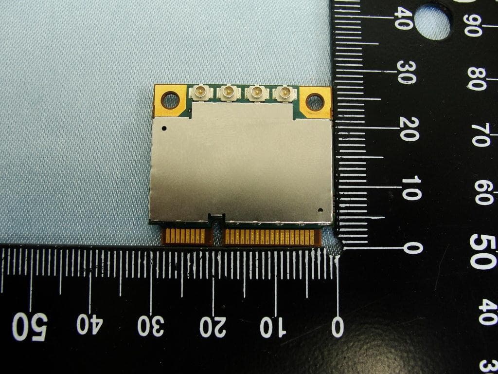
NCMOMO6792
Feb 24, 2013GTM679W
Equipment Class
JBP - Part 15 Class B Computing Device Peripheral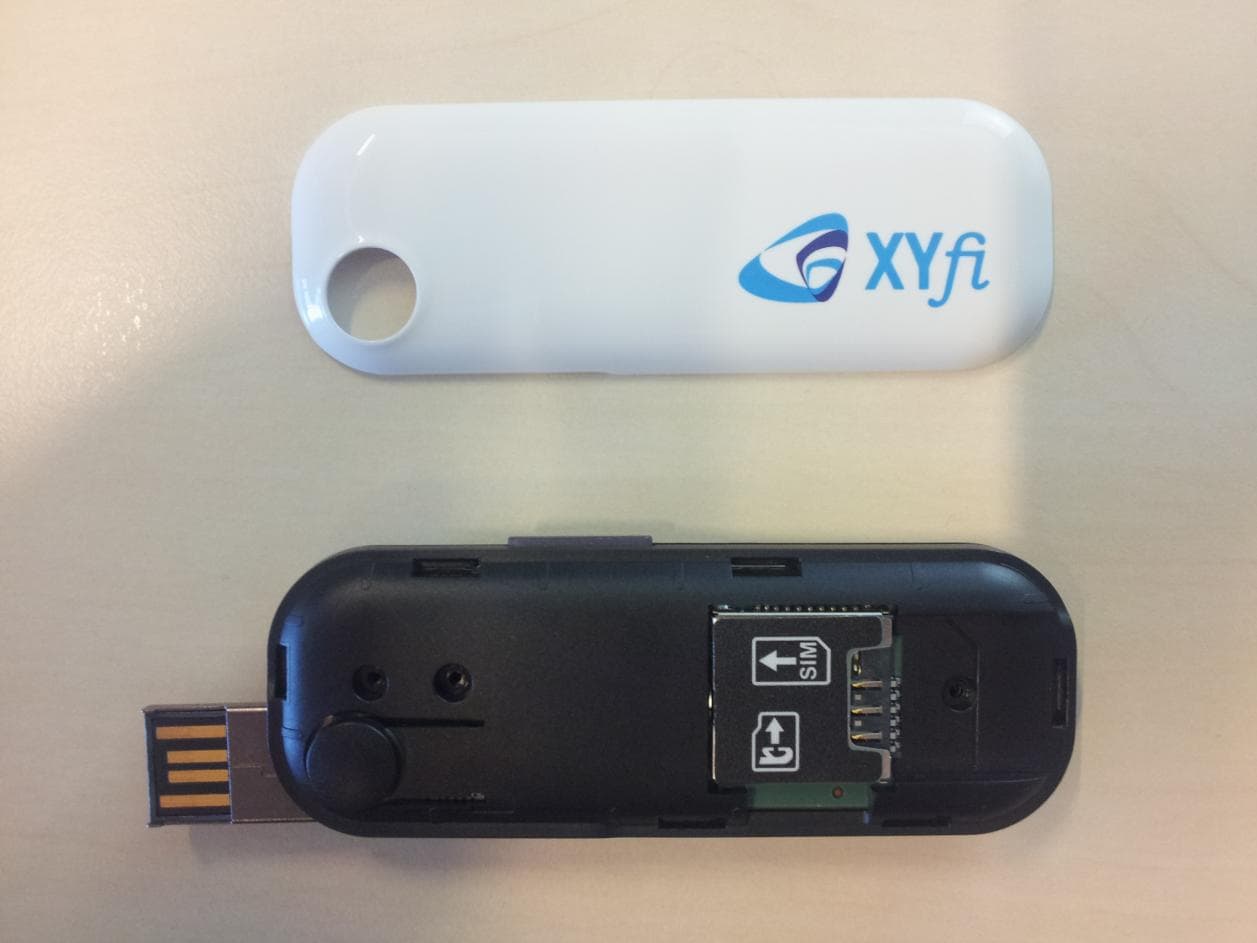
NCMOGI0643
Dec 22, 2011Quadband GSM/GPRS/EDGE Triband UMTS/HSDPA/HSUPA USB Modem
Equipment Class
JBP - Part 15 Class B Computing Device Peripheral