NCMOGE0002CardBus to ExpressCard Adapter
Option (Crescent NV)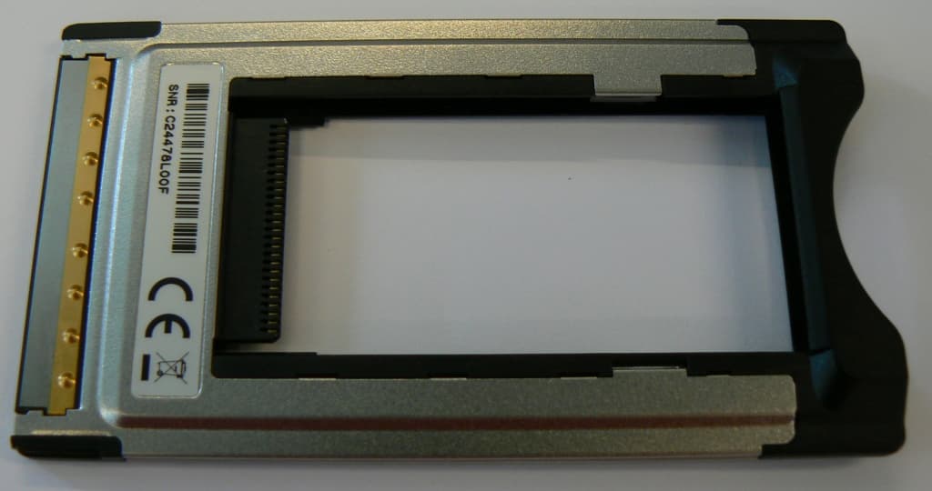
Click to zoom
Application Details
- Equipment Class
- JBP - Part 15 Class B Computing Device Peripheral
- Date of Grant
- Sep 23, 2007
- Application Purpose
- Original Equipment
- Date of Application
- Sep 23, 2007
- Equipment Note
- CardBus to ExpressCard Adapter
- Company
- Option (Crescent NV)
- Country
- Belgium
Documents & Files
Document Text
Text extracted from the exhibit documents filed with the FCC. Open a document above to read the original.
Users Manual
About GlobeTrotter EX Converter (Model: GE 0002) The GlobeTrotter Ex Converter enables a user to operate one of our Globe- Trotter ExpressCard cards in a laptop equipped with a Cardbus interface. Our converter is unique because it co-operates with our data cards without sac- rificing data card performance and ensuring at the same time that Cardbus specifications are not exceeded. Its design minimizes wasted power by our choice for efficient voltage conversion, controller logic and intelligent power conversion. Based on our years of experience as market leader, the choice for this design ensures the widest possible compatibility with laptops under all conditions, AC or Battery powered, in good or bad 3G / 2G coverage under the most demanding coding conditions (when peak power is consumed). Features • High speed Cardbus (32-bit 3.3V interface) • Cardbus compliant power management • Co-operative power management with Option ExpressCards • Low power host controller • High efficiency voltage conversion to minimize heat generation • Cardbus Current limit protection • Works with all Option ExpressCard / 34 devices GlobeTrotter EX Converter • ExpressCard / 34 to Cardbus technology converter • Use your Option ExpressCard in a PCMCIA slot • Smallest high performance converter on the market • Overload protection for your computer • Active electronics for maximum power • No loss of datacard speed • Type: Cardbus 32-bit 3.3V interface ExpressCard/34 • Current limiting to 1A • RoHS Compliant Hardware specifications Gaston Geenslaan 14 - 3001 Leuven Belgium - T +32 16 317 411 - F +32 16 207 164 - www.option.com GlobeTrotter EX CONVERTER As part of their continual product improvement process, Option reserve the right to alter the specifications for the product detailed here. “GlobeTrotter Express” is a registered trademark of Option. The Apple logo, Mac and Mac OS are trademarks of Apple Computer, Inc. RoHS COMPLIANT Model: GE 0002
Users Manual
Important Information! Using your GlobeTrotter Ex Converter GE 0002. Using it for the first time: 1. Insert the Converter in to the PC-Card slot first. 2. Wait a few seconds for Windows ® to complete its new hardware installation. 3. Now you are ready to follow the installation guidelines for your data card. Using the Converter After installation: We recommend that you insert the Converter in to the PC-Card slot first and then insert the data card in to the Converter. Safe Removal: 1. Please save any documents first. 2. If you are connected to the Internet with your data card please stop the connection. 3. Click the “Safely Remove Hardware” icon in the system tray. 4. Click “Standard Enhanced PCI to USB Host Controller” or “Standard OpenHCD USB Host Controller”. 5. You can now remove the Converter and data card together from the PC-Card slot. Important note for Windows ® 2000 users: If you are asked to reboot your machine during the installation of the communication software you should remove the data card and Converter before the reboot and then re-insert them when Windows ® has loaded. Some Windows ® 2000 computers will not detect the data card and Converter properly if they are fitted during a power up or reboot. The solution is to remove the Converter before powering or rebooting the computer. Wichtige Kundeninformation! Wie verwenden Sie Ihren GlobeTrotter Ex Converter GE 0002 zu Ihrem besten Nutzen. Erstmaliges Verwenden des Converters: 1. Stecken Sie zuerst den Converter in den PC-Karten Slot Ihres Computers. 2. Warten Sie einige Sekunden bis Windows seinen Installationsprozess für neue Hardware abgeschlossen hat. 3. Installieren Sie nun die Datenkarte und folgen deren Benutzerhinweisen. Verwendung des Converter nachdem er bereits einmal installiert wurde: Wir empfehlen Ihnen jeweils den Converter zuerst in den PC-Karten Slot einzustecken bevor Sie die Datenkarte hinzufügen. Sicheres Entfernen der Datenkarte: 1. Bitte speichern Sie zuerst alle Dokumente. 2. Sind sind über Ihre Datenkarte mit dem Internet verbunden dann beenden Sie bitte diese Verbindung. 3. Klicken Sie auf das “Hardware sicher entfernen” icon in der Systemleiste. 4. Klicken Sie auf “Standard Enhanced PCI to USB Host Controller” oder “Standard OpenHCD USB Host Controller”. 5. Nach erfolgreicher Rückmeldung von Windows können Sie nun die Datenkarte und den Converter aus dem PC-Karten Slot entfernen. Wichtiger Hinweis für Windows ® 2000 Nutzer: Falls Sie während des Installationsprozesses aufgefordert warden Ihren Computer erneut zu starten entfernen Sie bitte zuvor die Datenkarte und den Converter. Sobald das Betriebssystem wieder erfolgreich gestartet wurde können Sie den Converter und die Datenkarte wieder einstecken. Falls Sie den Converter oder / und die Datenkarte während eines Starts oder eines erneuten Starts des Computer einstecken kann es vorkommen dass einige Windows ® 2000 Computer den Converter und die Datenkarte nicht korrekt erkennen. In diesem Fall entfernen Sie bitte den Converter BEVOR Sie das Gerät anschalten oder erneut starten. Belangrijke informatie! Correct gebruik van uw GlobeTrotter Ex Converter GE 0002 Bij het eerste gebruik: 1. Plaats de Converter eerst in het PC-kaart slot van uw PC. 2. Windows ® start met de installatie van ‘nieuwe hardware’. Wacht enkele seconden tot dit voltooid is. 3. U kunt nu verder met de installatie van uw datakaart zoals in de installatie handleiding van uw datakaart beschreven staat. Gebruik van de Converter achteraf: We raden U aan om eerst de converter in het PC-kaart slot te steken en daarna de datakaart in de converter te steken. Veilig verwijderen: 1. Gelieve eerst alle open documenten op te slaan. 2. Als u nog verbonden bent met het internet via uw datakaart, dan dient deze verbinding eerst gestopt te worden. 3. Klik op het icoontje van “Harware Veilig Verwijderen” in de systeembalk. 4. Klik op “Standard Enhanced PCI to USB Host Controller” of “Standard OpenHCD USB Host Controller”. 5. U kunt nu de converter en de datakaart samen uit uw laptop halen. Belangrijke opmerking voor Windows ® 2000 gebruikers: Wanneer er gevraagd wordt om de PC te herstarten tijdens het installatieproces van de software, gelieve dan eerst de datakaart en de converter te verwijderen alvorens te herstarten en ze opnieuw in te steken nadat Windows ® herstart is. Sommige computers die op Windows ® 2000 werken zullen immers de datakaart en converter niet correct herkennen wanneer deze in de laptop steken tijdens het opstarten. De oplossing bestaat erin om deze te verwijderen alvorens de PC te herstarten. Information importante ! Utilisation de votre convertisseur GlobeTrotter Ex Converter GE 0002 Lors de la première utilisation : 1. Insérez d’abord le convertisseur dans le slot PC-card. 2. Patientez quelques secondes que Windows termine l’installation du nouveau matériel. 3. Vous pouvez maintenant poursuivre l’installation normale de votre carte modem. Utilisation du convertisseur après installation : Nous vous recommandons de d’abord insérer le convertisseur seul dans le slot PC-card et d’ensuite insérer la carte dans le convertisseur. Safe Removal (suppression sécurisée de périphérique) : 1. Prière de sauvez vos documents en cours. 2. Si vous êtes connecté à Internet via votre carte modem, prière de vous déconnecter. 3. Cliquez sur l’icône “Suppression sécurisée de périphériques” dans la barre système (system tray). 4. Cliquez sur “Standard Enhanced PCI to USB Host Controller” ou “Standard OpenHCD USB Host Controller”. 5. Vous pouvez maintenant retirer l’ensemble convertisseur/carte de votre slot PC-Card. Note importante pour les utilisateurs de Windows ® 2000 : Si le système vous demande de redémarrer votre machine lors de l’installation du logiciel de communication, veuillez retirer la carte et le convertisseur avant de redémarrer et les réinsérer lorsque le chargement de Windows est terminé. Certains ordinateurs sous Windows ® 2000 ne détectent pas correctement la présence du conv…
Text truncated - open the document above for the full version.
Users Manual
GE0002 Federal communications commission notice This device complies with Part 15 of the FCC rules. Operation is subject to the following two conditions: (1) this device may not cause harmful interference, and (2) this device must accept any interference received, including interference that may cause undesired operation. Any changes or modifications not expressly approved by the party responsible for compliance could void the user's authority to operate the equipment. This equipment has been tested and found to comply with the limits for a Class B digital device, pursuant to Part 15 of the FCC Rules. These limits are designed to provide reasonable protection against harmful interference in a residential installation. This equipment generates uses and can radiate radio frequency energy and, if not installed and used in accordance with the instructions, may cause harmful interference to radio communications. However, there is no guarantee that interference will not occur in a particular installation. If this equipment does cause harmful interference to radio or television reception, which can be determined by turning the equipment off and on, the user is encouraged to try to correct the interference by one or more of the following measures: - Reorient or relocate the receiving antenna. - Increase the separation between the equipment and receiver. - Connect the equipment into an outlet on a circuit different from that to which the receiver is connected. - Consult the dealer or an experienced radio/TV technician for help. For questions regarding your product or FCC declaration, contact: Option | Gaston Geenslaan 14| 3001 Leuven | Belgium www.option.com To identify this product, refer to the Part, Series, or Model number found on the product. This product may be used in the following countries: > All EU Member states > Iceland > Switzerland > Norway > United States of America Manufacturer's Disclaimer Statement The information in this document is subject to change without notice and does not represent a commitment on the part of the vendor. No warranty or representation, either expressed or implied, is made with respect to the quality, accuracy, or fitness for any particular purpose of this document. The manufacturer reserves the right to make changes to the content of this document and/or the products associated with it at any time without obligation to notify any person or organization of such changes. In no event will the manufacturer be liable for direct, indirect, special, incidental, or consequential damages arising out of the use or inability to use this product or documentation, even if advised of the possibility of such damages. For questions regarding your product or declaration, contact: Option | Gaston Geenslaan 14| 3001 Leuven | Belgium www.option.com
Test Report
7 layers AG Aufsichtsratsvorsitzenderh Registergerichth registered in: Borsigstrasse 11 Chairman of the Supervisory Board: Düsseldorf, HRB 44096 40880 Ratingen, Germany Markus Becker USt-IdNr h VAT Nr: Phone: +49 (0) 2102 749 0 Vorstandh Board: DE 203159652 Fax: +49 (0) 2102 749 350 Dr. Hans-Jürgen Meckelburg www.7Layers.com René Schildknecht InterLab ® is a registered trademark of 7 layers AG FCC Measurement/Technical Report on GlobeTrotter Ex Converter Report Reference: MDE_Opti_0715_FCCa Test Laboratory: 7 layers AG Borsigstrasse 11 40880 Ratingen Germany email: [email protected] DAT-P-192/99-01 Note: The following test results relate only to the devices specified in this document. This report shall not be reproduced in parts without the written approval of the testing laboratory. Test report Reference: MDE_Opti_0715_FCCa Page 2 of 23 Table of Contents 0 Summary 3 0.1 Technical Report Summary 3 0.2 Measurement Summary 4 1 Administrative Data 5 1.1 Testing Laboratory 5 1.2 Project Data 5 1.3 Applicant Data 5 1.4 Manufacturer Data 5 2 Product labelling 6 2.1 FCC ID label 6 2.2 Location of the label on the EUT 6 3 Test object Data 7 3.1 General EUT Description 7 3.2 EUT Main components 8 3.3 Ancillary Equipment 8 3.4 EUT Setups 9 3.5 Operating Modes 9 4 Test Results 10 4.1 Conducted emissions (AC power line) 10 4.2 Spurious radiated emissions 12 5 Test Equipment 15 6 Photo Report 18 7 Setup Drawings 21 8 Annex measurement plots 22 8.1 AC Mains conducted 22 8.2 Radiated Emissions 23 Test report Reference: MDE_Opti_0715_FCCa Page 3 of 23 0 Summary 0.1 Technical Report Summary Type of Authorization Certification for an Unintentional Radiator (Class B digital device) Applicable FCC Rules Prepared in accordance with the requirements of FCC Rules and Regulations as listed in 47 CFR Ch.1 Parts 2 (10-1-06 Edition) and 15 (10-1-06 Edition). The following subparts are applicable to the results in this test report. Part 2, Subpart J - Equipment Authorization Procedures, Certification Part 15, Subpart A – General § 15.31 Measurement standards § 15.33 Frequency range of radiated measurements Part 15, Subpart B – Unintentional Radiators § 15.101 Equipment authorization of unintentional radiators § 15.107 Conducted limits § 15.109 Radiated emission limits Note: None. Summary Test Results: The EUT complied with all performed tests as listed in chapter 0.2 Measurement Summary. layers 0.2 Measurement Summary FCC Part 15, Subpart B § 15.107 Conducted Emissions (AC power line) The measurement was performed according to ANSI C63.4 OP-Mode Setup Port op-mode 1 Setup_Ol AC Port (power line) FCC Part 15, Subpart B § 15.109 Spurious Radiated Emissions The measurement was performed according to ANSI C63.4 OP-Mode Setup Port op-mode 1 Setup_Ol Enclosure , ayers 7 layers AG, Borsigstr. 11 40880 Ratingen, Germany Ph::me +49 (0)2102 749 0 Responsible for ~ " I . Responsible Accreditation Scope: __/~/L...:oO\.~ ...C/\"--,,--,,,,e.-/U,---=--=.C,---for Test Report: 2003 Final Result passed 2003 Final Result passed Page 4 of23 Test report Reference: MDE_Opti_0715_FCCa Page 5 of 23 1 Administrative Data 1.1 Testing Laboratory Company Name: 7 Layers AG Address Borsigstr. 11 40880 Ratingen Germany This facility has been fully described in a report submitted to the FCC and accepted under the registration number 96716. The test facility is also accredited by the following accreditation organisation: - Deutscher Akkreditierungs Rat DAR-Registration no. DAT-P-192/99-01 Responsible for Accreditation Scope: Dipl.-Ing. Bernhard Retka Dipl.-Ing. Robert Machulec Dipl.-Ing. Thomas Hoell Report Template Version: 2007-07-16 1.2 Project Data Responsible for testing and report: Dipl.-Ing. Andreas Petz Date of Test(s): 2007-07-26 Date of Report: 2007-08-06 1.3 Applicant Data Company Name: Option NV Address: Gaston Geenslaan 14 3001 Leuven Belgium Contact Person: Mr. Lodeweyckx 1.4 Manufacturer Data Company Name: please see applicant data Address: Contact Person: Test report Reference: MDE_Opti_0715_FCCa Page 6 of 23 2 Product labelling 2.1 FCC ID label At the time of the report there was no FCC label available. 2.2 Location of the label on the EUT see above Test report Reference: MDE_Opti_0715_FCCa Page 7 of 23 3 Test object Data 3.1 General EUT Description Equipment under Test ExpressCard to PCMCIA adaptor Type Designation: GlobeTrotter Ex Converter Kind of Device: (optional) Computer Accessory Voltage Type: DC Voltage level: 5 V (supplied by laptop) General product description: The device adapts ExpressCards for the usage in PCMCIA slots in computers and is intended to be used in combination with GSM/UMTS data cards. The EUT provides the following ports: Ports Enclosure PCMCIA interface (connector) ExpressCard interface (connector) AC port (power line, of AC/DC converter of laptop) The main components of the EUT are listed and described in Chapter 3.2 Test report Reference: MDE_Opti_0715_FCCa Page 8 of 23 3.2 EUT Main components Type, S/N, Short Descriptions etc. used in this Test Report Short Description Equipment under Test Type Designation Serial No. HW Status SW Status Date of Receipt EUT A (Code: 37280c01) ExpressCard to PCMCIA adaptor GlobeTrotter Ex Converter CM4476B01T 4.0 – 2007-07-12 Remark: none NOTE: The short description is used to simplify the identification of the EUT in this test report. 3.3 Ancillary Equipment For the purposes of this test report, ancillary equipment is defined as equipment which is used in conjunction with the EUT to provide operational and control features to the EUT. It is necessary to configure the system in a typical fashion, as a customer would normally use it. But nevertheless Ancillary Equipment can influence the test results. Short Description Equipment under Test Type Designation HW Status SW Status Serial no. FCC ID AE1 Printer Epson Stylus C84 – – FBPT048906 – AE2 Keyboard Cherry RS6000 – – G0000273 – AE3 Mouse Logitech M-BB48 – – LZC9050547 8 – AE4 Monitor LG Flatron L1740BQ – – 509WANF1 W607…
Text truncated - open the document above for the full version.
Test Setup Photos
Test report Reference: MDE_Opti_0715_FCCa Page 1 of 3 TTT Test setup Photos Photo 1: Test setup for radiated measurements Photo 2: Test setup for radiated measurements (rear side) Test report Reference: MDE_Opti_0715_FCCa Page 2 of 3 Photo 3: Test setup for conducted measurements Photo 4: EUT (front side) Test report Reference: MDE_Opti_0715_FCCa Page 3 of 3 Photo 5: EUT (rear side) Photo 6: GSM/UMTS ExpressCard (auxiliary equipment, the photo shows an identical sample which was not used for the tests)
Contact Information
Applicant
Joost van der Velden(CEO)
Test Firm
7layers AGRobert Machulec
Technical Specifications
| # | Rule Parts | Frequency Range | Power Output |
|---|---|---|---|
| 1 | 15B | - | - |
Other Applications from Option (Crescent NV)

NCM-CG2132
Sep 21, 2022LoRaWAN 86x/9xx Expansion card
Equipment Class
DTS - Digital Transmission System
NCM-WT500
Jun 06, 2021Water and Temperature Sensor
Equipment Class
DSS - Part 15 Spread Spectrum Transmitter
NCMOCG2101
Feb 27, 2013CloudGate 802.11abgn Wireless LAN Card
Equipment Class
NII - Unlicensed National Information Infrastructure TX
NCMOMO6792
Feb 24, 2013GTM679W
Equipment Class
JBP - Part 15 Class B Computing Device PeripheralNCMOGI0644
Jun 17, 2012GSM/UMTS/WLAN USB Modem GI0644
Equipment Class
PCB - PCS Licensed Transmitter