NCMOGI0031Multimode GSM/GPRS/EDGE Modem
Option (Crescent NV)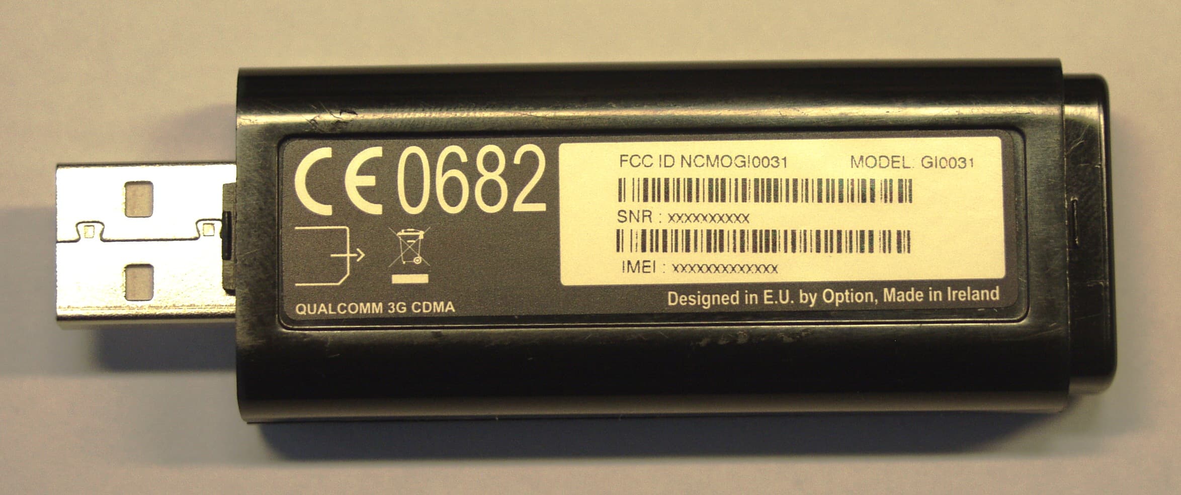
Click to zoom
Application Details
- Equipment Class
- PCB - PCS Licensed Transmitter
- Date of Grant
- Dec 20, 2007
- Application Purpose
- Original Equipment
- Date of Application
- Dec 20, 2007
- Equipment Note
- Multimode GSM/GPRS/EDGE Modem
- Frequency Range
- 1850.20000000 - 1909.80000000
- Company
- Option (Crescent NV)
- Country
- Belgium
Documents & Files
Document Text
Text extracted from the exhibit documents filed with the FCC. Open a document above to read the original.
Users Manual
1 Insert the SIM card in the SIM slot of the iCON 031 The SIM slot is located above the USB connector on the front of the device. Simply slide in your SIM card. 2 Insert the i CON 031 into your computer. Start up your computer and insert the i CON 031 in a free USB slot of your computer. 3 Install Software & Drivers Software and driver installation will start up automatically. An installer window will open: Installation will then commence. When the “Installation Completed” screen appears, click “Finish” and you are ready to connect to the internet. CONNeCtINg tO the INterNet 1 Start up your computer and insert the i CON 031 with an installed SIM card in a free USB slot of your computer. PreParINg FOr FIrSt USe Thank you for buying this Option device. Follow the next three steps to install your i CON 031 and to prepare it for your first connection. For more detailed instructions and information you can always consult the user manuals (user manual, GT Connect for Windows user manual). i CON 031 Quick Start Guide 2 enter your SIM pincode (not necessary if you disabled the pincode on your SIM card) 3 Connecting: You are now ready to connect to the Internet by using the GlobeTrotter Connect application in the system tooltray: Simply double-click on it to fully open the application and then click ‘connect’ Remark: It might be that you have to enter connection settings or choose an operator profile manually. Please consult the software user guide for more details on this. StatUS INDICatOr LED statusMeaning of LED Status • Off • Triple blink • Double blink • Single blink • Blinks fast iCON 031 not powered Power Up, Network Scan or PIN required Ready to connect to 2G or EDGE networks Connected A problem occurred. Problem causes can be checked in the user manual or simply disconnect and reconnect the iCON 031 to the computer. If you have any technical problems with this product, feel free to contact our support team at www.option.com/support/index.shtml Copyright Option nv © 2007 all rights reserved. No parts may be reproduced without written permission.
Users Manual
Option GI0031 USB Modem CE 0700 FCC-ID: NCMOGI0031 Safety Leaflet Your USB Modem is like a mobile phone Your USB Modem uses the same technology as a mobile phone. It is important that you always obey all safety regulations related to mobile phone use. If you have any doubt about the safe operation of your USB Modem you should remove the USB Modem from the PC and seek advice from authorized personnel. This device may not be connected to a USB hub, nor to a PC network, nor to a USB 1.0 interface. 1. Safety Measurements Please read the following guidelines carefully. Not following these guidelines can cause harm to the USB stick, yourself or other persons. 1.1 General recommendations for use Always treat your product with care and keep in a clean and dust-free place. Do not expose your product to open flames or lit tobacco products. Do not expose to liquid, moisture or humidity. Do not expose the USB Modem to rain, or other liquids. Do not drop, throw or try to bend your product. Do not paint your product. Do not attempt to disassemble your product. Doing so may be dangerous and it will void the warranty. Do not touch the antenna unnecessarily. 1.2 Traveling: Handle the USB stick with care while traveling. It is recommended to remove the USB stick from the laptop. 1.3 Ambient temperatures: Do not expose the USB Modem or the antenna to ambient temperatures beyond the range of -10 and +55 degrees Celsius. 1.4 Explosive atmosphere: Turn off your PC in any area with a potentially explosive atmosphere. It is rare, but your PC could generate sparks, which could cause an explosion or fire. Areas with a potentially explosive atmosphere are not always clearly marked. They include fuelling areas (petrol filling stations), below deck on boats, fuel or chemical transfer or storage facilities, and areas where the air contains chemicals or particles, such as grain, dust, or metal powders. Do not transport or store your PC and accessories in the compartment of a vehicle, which contains flammable gas, liquid, or explosives. 1.5 Blasting areas – construction sites: Turn off your PC when in a blasting area in order to avoid interfering with two- way radios used in blasting operations. 1.6 Do not use on aircraft: Using a wireless devices on aircraft can cause interference and is illegal. Remove your USB Modem if you intend to use your PC whilst in an aircraft. Do not use it when the plane is on the ground without permission from the aircraft crew. 1.7 Do not use in hospitals: Please ensure you follow any local regulations or rules. People are often asked to switch off all electronic devices in some areas of a hospital; this is a recommendation that Option fully supports. Using the USB Modem close to sensitive electronic devices could possibly result in interference. If you intend to use your PC in such areas, you must remove the USB Modem. 1.8 Interference from radio signals: Option relies on advice from health authorities and relevant expert bodies about potential undesired responses to radio emissions from the USB Modem. 1.9 Immunity to interference: Electromagnetic interference is the disturbance of the normal operation of a device due to its undesired response to radio signals from an external source. Occasionally in some situations you may hear short sounds coming from audio equipment such as radio or multimedia PC. However, these audible signals do not interfere with the operation of the equipment. The 1989 Directive from the European Commission (89/336/ECC)13 governing all forms of electronic equipment concerns interference that such equipment produces and its immunity to interference from outside. Any equipment compliant with that directive is unlikely to suffer interference. All wireless devices may get interference, which could affect performance. 1.10 Cardiac pacemakers, implanted defibrillators & other medical implant devices It is possible that the USB Modem may interfere with some types of pacemakers or implanted defibrillators when operated close to the implanted device. You should seek advice from your doctor that is specific to the implant before using the USB Modem. Health authorities in many countries have set up advisory services for medical devices and implants including providing advice about maintaining separation distance between the mobile device or other radio frequency equipment and the implant. Option operating companies reflect the advice given by their relevant health authority or national advisory service and/or as a minimum indicate a separation distance of at least 20 cm between the USB Modem or other radio frequency terminal equipment and the embedded device. 1.11 Hearing devices: People with hearing aids or other cochlear implants may experience interfering noises when using mobile devices or when one is nearby. The level of interference will depend on the type of mobile device, the type of hearing device and the distance between the two. Increasing the distance between the USB Modem and hearing device may reduce interference. 1.12 Children: Do not allow children to play with your USB Modem. They could hurt themselves or others, or could accidentally damage the USB Modem. Your USB Modem contains small parts with sharp edges that may cause an injury or which could become detached and create a choking hazard. 1.13 Driving: Do NOT use the USB Modem while driving; park the vehicle first. 1.14 SIM cards: To protect against damage from electrostatic discharge (ESD) do not touch the SIM card connectors. As a precaution, always make sure that USB Modem is already in your hand before you insert or remove the SIM card. 1.15 Accessories: Only use Option approved accessories. Do not connect with incompatible products. When used with accessories Option can only guarantee safe and correct operation of our products if the accessories are tested and approved by us. 1.16 Safe distance: The USB Modem has been thoroughly tested to comply with SAR requirements. These tests simulate …
Text truncated - open the document above for the full version.
RF Exposure Info
DAT-P-152/98-01 SAR Report_7layers_6620_663_FCC_Body_850_1900_GI0031 Page 1 of 36 Report Dosimetric Assessment of the Portable Device GI0031 from Option (FCC ID: NCMOGI0031) tested in three host products According to the FCC Requirements November 20, 2007 IMST GmbH Carl-Friedrich-Gauß-Str. 2 D-47475 Kamp-Lintfort Customer 7layers AG Borsigstrasse 11 D-40880 Ratingen The test results only relate to the items tested. This report shall not be reproduced except in full without the written approval of the testing laboratory. Dasy_Report_FCC_Body_Card_GSM850_GSM1900_WCDMA_II_V_1.1.doc/14.08.2007/CH SAR Report_7layers_6620_663_FCC_Body_850_1900_GI0031 Page 2 of 36 Dasy_Report_FCC_Body_Card_GSM850_GSM1900_WCDMA_II_V_1.1.doc/14.08.2007/CH Executive Summary The device GI0031 is a new USB card from Option operating in the 850 MHz, 900 MHz, 1800 MHz and 1900 MHz frequency range. The device has an integrated antenna and the system concepts used are the GPRS 850 (Class 12), GPRS 900 (Class 12), GPRS 1800 (Class 12) and GPRS 1900 (Class 12). The objective of the measurements done by IMST was the dosimetric assessment of one device in body worn configuration in the GPRS 850 (Class 10) and GPRS 1900 (Class 11). The measurements were performed in combination with three different host products (BenQ Joybook S72, HP Compaq 6510b and Toshiba Tecra A9). The device was tested in lap held position with the bottom of the computer in direct contact against the flat phantom. The examinations have been carried out with the dosimetric assessment system „DASY4“. The measurements were made according to the Supplement C to OET Bulletin 65 of the Federal Communications Commission (FCC) Guidelines [OET 65] for evaluating compliance of mobile and portable devices with FCC limits for human exposure (general population) to radiofrequency emissions. SAR Report_7layers_6620_663_FCC_Body_850_1900_GI0031 Page 3 of 36 Dasy_Report_FCC_Body_Card_GSM850_GSM1900_WCDMA_II_V_1.1.doc/14.08.2007/CH Compliance statement The Option GI0031 USB card (FCC ID: NCMOGI0031) is in compliance with the Federal Communications Commission (FCC) Guidelines [OET 65] for uncontrolled exposure. The USB card was tested for the following configurations: Body Worn for GPRS 850 (Class 10) and GPRS 1900 (Class 11) in lap held position with the bottom of the computer in direct contact against the flat phantom. The card was tested with three host products (BenQ Joybook S72, HP Compaq 6510b and Toshiba Tecra A9). Due to the used power reduction in GPRS Class 12, the tests for GSM 850 were conducted with GPRS Class 10 and for GSM 1900 with GPRS Class 11 to cover the worst case. Maximum SAR 1g = 1.39 W/kg (GPRS 1900 (Class 11), Channel 512, BenQ Joybook S72) prepared by: ........................................... reviewed by:............................................. Alexander Rahn André van den Bosch test engineer quality assurance engineer SAR Report_7layers_6620_663_FCC_Body_850_1900_GI0031 Page 4 of 36 Dasy_Report_FCC_Body_Card_GSM850_GSM1900_WCDMA_II_V_1.1.doc/14.08.2007/CH Table of Contents 1 SUBJECT OF INVESTIGATION.................................................................................................................... 5 2 THE IEEE STANDARD C95.1 AND THE FCC EXPOSURE CRITERIA................................................. 5 2.1 DISTINCTION BETWEEN EXPOSED POPULATION, DURATION OF EXPOSURE AND FREQUENCIES........... 6 2.2 DISTINCTION BETWEEN MAXIMUM PERMISSIBLE EXPOSURE AND SAR LIMITS....................................... 6 2.3 SAR LIMIT.................................................................................................................................................. 7 3 THE FCC MEASUREMENT PROCEDURE................................................................................................. 7 3.1 GENERAL REQUIREMENTS......................................................................................................................... 7 3.2 PHANTOM REQUIREMENTS........................................................................................................................ 7 3.3 POSITIONING OF MODULES IN PORTABLE DEVICES (PCMCIA CARDS, USB CARDS)............................ 8 3.4 TEST TO BE PERFORMED........................................................................................................................... 9 4 THE MEASUREMENT SYSTEM................................................................................................................. 10 4.1 PHANTOM................................................................................................................................................. 11 4.2 PROBE...................................................................................................................................................... 12 4.3 MEASUREMENT PROCEDURE.................................................................................................................. 13 4.4 UNCERTAINTY ASSESSMENT................................................................................................................... 14 5 SAR RESULTS............................................................................................................................................... 15 6 EVALUATION................................................................................................................................................. 17 7 APPENDIX....................................................................................................................................................... 19 7.1 ADMINISTRATIVE DATA............................................................................................................................ 19 7.2 DEVICE UNDER TEST AND TEST CONDITIONS......................................................................................... 19 7.3 TISSUE RECIPES...................................................................................…
Text truncated - open the document above for the full version.
RF Exposure Info
DAT-P-152/98-01 SAR Report_7layers_6620_663_FCC_850_1900_SAR Plots_GI0031 Page 1 of 10 Appendix for the Report Dosimetric Assessment of the Portable Device GI0031 from Option (FCC ID: NCMOGI0031) tested in three host products According to the FCC Requirements SAR Distribution Plots November 21, 2007 IMST GmbH Carl-Friedrich-Gauß-Str. 2 D-47475 Kamp-Lintfort Customer 7layers AG Borsigstrasse 11 D-40880 Ratingen The test results only relate to the items tested. This report shall not be reproduced except in full without the written approval of the testing laboratory. dasy_report_fcc_850_1900_plots_1.1.doc/04.07.2005/CH SAR Report_7layers_6620_663_FCC_850_1900_SAR Plots_GI0031 Page 2 of 10 dasy_report_fcc_850_1900_plots_1.1.doc/04.07.2005/CH Table of Contents 1 SAR DISTRIBUTION PLOTS, GPRS 850 BODY....................................................................................... 3 2 SAR DISTRIBUTION PLOTS, GPRS 1900 BODY..................................................................................... 6 3 SAR Z-AXIS SCANS (VALIDATION)........................................................................................................... 9 4 SAR Z-AXIS SCANS (MEASUREMENTS)................................................................................................ 10 SAR Report_7layers_6620_663_FCC_850_1900_SAR Plots_GI0031 Page 3 of 10 dasy_report_fcc_850_1900_plots_1.1.doc/04.07.2005/CH 1 SAR Distribution Plots, GPRS 850 Body Test Laboratory: IMST GmbH, DASY Blue (I); File Name: 014_bahl_1_BQ.da4 DUT: Option; Type: GI0031; Serial: 004401440650014 Program Name: Body Worn Communication System: GPRS 850; Frequency: 824.2 MHz;Duty Cycle: 1:4 Medium parameters used: f = 824.2 MHz; σ = 0.98 mho/m; ε r = 54.6; ρ = 1000 kg/m 3 Phantom section: Flat Section DASY4 Configuration: - Probe: ET3DV6R - SN1669; ConvF(6.22, 6.22, 6.22); Calibrated: 15.02.2007 - Sensor-Surface: 4mm (Mechanical Surface Detection) - Electronics: DAE4 Sn631; Calibrated: 17.09.2007 - Phantom: SAM Sugar 1059; Type: Speag; Serial: 1059 - Measurement SW: DASY4, V4.7 Build 53; Postprocessing SW: SEMCAD, V1.8 Build 172 Body Worn/Area Scan (7x10x1): Measurement grid: dx=15mm, dy=15mm Maximum value of SAR (measured) = 1.39 mW/g Body Worn/Zoom Scan (7x7x7)/Cube 0: Measurement grid: dx=5mm, dy=5mm, dz=5mm Reference Value = 31.5 V/m; Power Drift = -0.084 dB Peak SAR (extrapolated) = 2.05 W/kg SAR(1 g) = 1.37 mW/g; SAR(10 g) = 0.879 mW/g Maximum value of SAR (measured) = 1.49 mW/g Fig. 1: SAR distribution for GPRS 850 (Class 10), channel 128, Lap Held Position (BenQ Joybook S72, November 19, 2007; Ambient Temperature: 21.5°C; Liquid Temperature: 20.8°C). Notebook region Antenna region X SAR Report_7layers_6620_663_FCC_850_1900_SAR Plots_GI0031 Page 4 of 10 dasy_report_fcc_850_1900_plots_1.1.doc/04.07.2005/CH Test Laboratory: IMST GmbH, DASY Blue (I); File Name: 014_bahl_1_HP.da4 DUT: Option; Type: GI0031; Serial: 004401440650014 Program Name: Body Worn Communication System: GPRS 850; Frequency: 824.2 MHz;Duty Cycle: 1:4 Medium parameters used: f = 824.2 MHz; σ = 0.98 mho/m; ε r = 54.6; ρ = 1000 kg/m 3 Phantom section: Flat Section DASY4 Configuration: - Probe: ET3DV6R - SN1669; ConvF(6.22, 6.22, 6.22); Calibrated: 15.02.2007 - Sensor-Surface: 4mm (Mechanical Surface Detection) - Electronics: DAE4 Sn631; Calibrated: 17.09.2007 - Phantom: SAM Sugar 1059; Type: Speag; Serial: 1059 - Measurement SW: DASY4, V4.7 Build 53; Postprocessing SW: SEMCAD, V1.8 Build 172 Body Worn/Area Scan (7x10x1): Measurement grid: dx=15mm, dy=15mm Maximum value of SAR (measured) = 1.31 mW/g Body Worn/Zoom Scan (7x7x7)/Cube 0: Measurement grid: dx=5mm, dy=5mm, dz=5mm Reference Value = 32.0 V/m; Power Drift = -0.084 dB Peak SAR (extrapolated) = 1.82 W/kg SAR(1 g) = 1.23 mW/g; SAR(10 g) = 0.794 mW/g Maximum value of SAR (measured) = 1.33 mW/g Fig. 2: SAR distribution for GPRS 850 (Class 10), channel 128, Lap Held Position (HP Compaq 6510b, November 19, 2007; Ambient Temperature: 21.5°C; Liquid Temperature: 20.8°C). Notebook region Antenna region X SAR Report_7layers_6620_663_FCC_850_1900_SAR Plots_GI0031 Page 5 of 10 dasy_report_fcc_850_1900_plots_1.1.doc/04.07.2005/CH Test Laboratory: IMST GmbH, DASY Blue (I); File Name: 014_bahl_1_A9.da4 DUT: Option; Type: GI0031; Serial: 004401440650014 Program Name: Body Worn Communication System: GPRS 850; Frequency: 824.2 MHz;Duty Cycle: 1:4 Medium parameters used: f = 824.2 MHz; σ = 0.98 mho/m; ε r = 54.6; ρ = 1000 kg/m 3 Phantom section: Flat Section DASY4 Configuration: - Probe: ET3DV6R - SN1669; ConvF(6.22, 6.22, 6.22); Calibrated: 15.02.2007 - Sensor-Surface: 4mm (Mechanical Surface Detection) - Electronics: DAE4 Sn631; Calibrated: 17.09.2007 - Phantom: SAM Sugar 1059; Type: Speag; Serial: 1059 - Measurement SW: DASY4, V4.7 Build 53; Postprocessing SW: SEMCAD, V1.8 Build 172 Body Worn/Area Scan (7x10x1): Measurement grid: dx=15mm, dy=15mm Maximum value of SAR (measured) = 1.29 mW/g Body Worn/Zoom Scan (7x7x7)/Cube 0: Measurement grid: dx=5mm, dy=5mm, dz=5mm Reference Value = 28.9 V/m; Power Drift = -0.163 dB Peak SAR (extrapolated) = 2.02 W/kg SAR(1 g) = 1.25 mW/g; SAR(10 g) = 0.770 mW/g Maximum value of SAR (measured) = 1.35 mW/g Fig. 3: SAR distribution for GPRS 850 (Class 10), channel 128, Lap Held Position (Toshiba Tecra A9, November 19, 2007; Ambient Temperature: 21.5°C; Liquid Temperature: 20.8°C). Notebook region Antenna region X SAR Report_7layers_6620_663_FCC_850_1900_SAR Plots_GI0031 Page 6 of 10 dasy_report_fcc_850_1900_plots_1.1.doc/04.07.2005/CH 2 SAR Distribution Plots, GPRS 1900 Body Test Laboratory: IMST GmbH, DASY Blue (I); File Name: 014_bphm_1_BQ.da4 DUT: Option; Type: GI0031; Serial: 004401440650014 Program Name: Body Worn Communication System: GPRS 1900; Frequency: 1880 MHz;Duty Cycle: 1:2.66 Medium parameters used: f = 1880 MHz; σ = 1.5 mho/m; ε r = 54.7; ρ = 1000 kg/m 3 Phantom section: Flat Section DASY4 Configuration: - Probe: ET3DV6R - SN1669; ConvF(4.72, 4.72, 4.72); Calibrated: 15.0…
Text truncated - open the document above for the full version.
RF Exposure Info
DAT-P-152/98-01 SAR Report_7layers_6620_663_FCC_CalData_GI0031 dasy_report_fcc_850_1900_cal_data_2.0.doc/08.01.2005/CH Appendix for the Report Dosimetric Assessment of the Portable Device GI0031 from Option (FCC ID: NCMOGI0031) tested in three host products According to the FCC Requirements Calibration Data November 21, 2007 IMST GmbH Carl-Friedrich-Gauß-Str. 2 D-47475 Kamp-Lintfort Customer 7layers AG Borsigstrasse 11 D-40880 Ratingen This report shall not be reproduced except in full without the written approval of the testing laboratory. Dasy_Report_FCC_Body_Card_GSM850_GSM1900_WCDMA_II_V_1.1.doc/14.08.2007/CH
Test Report
7 layers AG Aufsichtsratsvorsitzenderh Registergerichth registered in: Borsigstrasse 11 Chairman of the Supervisory Board: Düsseldorf, HRB 44096 40880 Ratingen, Germany Markus Becker USt-IdNr h VAT Nr: Phone: +49 (0) 2102 749 0 Vorstandh Board: DE 203159652 Fax: +49 (0) 2102 749 350 Dr. Hans-Jürgen Meckelburg TAX No. 147/5869/0385 www.7Layers.com René Schildknecht InterLab ® is a registered trademark of 7 layers AG FCC Measurement/Technical Report on GSM USB Modem GI0031 Report Reference: MDE_Opti_0718_FCCd Test Laboratory: 7 layers AG Borsigstrasse 11 40880 Ratingen Germany email: [email protected] DAT-P-192/99-01 Note: The following test results relate only to the devices specified in this document. This report shall not be reproduced in parts without the written approval of the testing laboratory. Test report Reference: MDE_Opti_0718_FCCd Page 2 of 53 Table of Contents 0 Summary 3 0.1 Technical Report Summary 3 0.2 Measurement Summary 4 1 Administrative Data 6 1.1 Testing Laboratory 6 1.2 Project Data 6 1.3 Applicant Data 6 1.4 Manufacturer Data 6 2 Testobject Data 7 2.1 General EUT Description 7 2.2 EUT Main components 8 2.3 Ancillary Equipment 8 2.4 EUT Setups 8 2.5 Operating Modes 9 3 Test Results 10 3.1 RF Power Output 10 3.2 Frequency stability 13 3.3 Spurious emissions at antenna terminals 17 3.4 Field strength of spurious radiation 21 3.5 Emission and Occupied Bandwidth 25 3.6 Band edge compliance 28 4 Test Equipment 30 5 Photo Report 33 6 Setup Drawings 36 7 Annex 38 Measurement Plots Test report Reference: MDE_Opti_0718_FCCd Page 3 of 53 0 Summary 0.1 Technical Report Summary Type of Authorization Certification for a GSM cellular radiotelephone device Applicable FCC Rules Prepared in accordance with the requirements of FCC Rules and Regulations as listed in 47 CFR Ch.1 Parts 0 to 19 and Parts 20 to 69 (10-1-06 Edition). The following subparts are applicable to the results in this test report. Part 2 Subpart J - Equipment Authorization Procedures, Certification § 2.1046 Measurement required: RF power output § 2.1049 Measurement required: Occupied bandwidth § 2.1051 Measurement required: Spurious emissions at antenna terminals § 2.1053 Measurement required: Field strength of spurious radiation § 2.1055 Measurement required: Frequency stability § 2.1057 Frequency spectrum to be investigated Part 22 Subpart C – Operational and Technical Requirements § 22.355 Frequency tolerance Subpart H – Cellular Radiotelephone Service § 22.913 Effective radiated power limits § 22.917 Emission limitations for cellular equipment Summary Test The EUT complied with all performed tests as listed in chapter 0.2 Measurement Summary. Test report Reference: MDE_Opti_0718_FCCd Page 4 of 53 0.2 Measurement Summary RF Power Output The measurement was performed according to FCC §2.1046 10-1-06 OP-Mode Setup Port Final Result op-mode 1 Setup_a01 Temp.ant.connector passed op-mode 2 Setup_a01 Temp.ant.connector passed op-mode 3 Setup_a01 Temp.ant.connector passed op-mode 4 Setup_a01 Temp.ant.connector passed op-mode 5 Setup_a01 Temp.ant.connector passed op-mode 6 Setup_a01 Temp.ant.connector passed Frequency stability The measurement was performed according to FCC §2.1055 10-1-06 OP-Mode Setup Port Final Result op-mode 2 Setup_a01 Temp.ant.connector passed op-mode 5 Setup_a01 Temp.ant.connector passed Spurious emissions at antenna terminals The measurement was performed according to FCC §2.1051 10-1-06 OP-Mode Setup Port Final Result op-mode 1 Setup_a01 Temp.ant.connector passed op-mode 2 Setup_a01 Temp.ant.connector passed op-mode 3 Setup_a01 Temp.ant.connector passed op-mode 4 Setup_a01 Temp.ant.connector passed op-mode 5 Setup_a01 Temp.ant.connector passed op-mode 6 Setup_a01 Temp.ant.connector passed Field strength of spurious radiation The measurement was performed according to FCC §2.1053 10-1-06 OP-Mode Setup Port Final Result op-mode 1 Setup_a02 enclosure passed op-mode 2 Setup_a02 enclosure passed op-mode 3 Setup_a02 enclosure passed op-mode 4 Setup_a02 enclosure passed op-mode 5 Setup_a02 enclosure passed op-mode 6 Setup_a02 enclosure passed Emission and Occupied Bandwidth The measurement was performed according to FCC §2.1049 10-1-06 OP-Mode Setup Port Final Result op-mode 1 Setup_a01 Temp.ant.connector passed op-mode 2 Setup_a01 Temp.ant.connector passed op-mode 3 Setup_a01 Temp.ant.connector passed op-mode 4 Setup_a01 Temp.ant.connector passed op-mode 5 Setup_a01 Temp.ant.connector passed op-mode 6 Setup_a01 Temp.ant.connector passed "ayers Band edge compliance The measurement was performed according to FCC §2.1053 10-1-06 OP-Mode Setup Port Final Result op-mode 1 Setup_a01 Temp.ant.connector passed op-mode 3 Setup_aD1 Temp.ant.connector passed op-mode 4 Setup_a01 Temp.ant.connector passed op-mode 6 Setup_aD1 Temp.ant.connector passed This report replaces the test report MDE_Opti_D718_FCCa • layers gv 7 layers AG, Borsigstr. 11 40880 Ratingen, GermallY Pilone +49 (0)2102 749 0 Responsible for /J,-J _ A / Responsible Accred itation Scope: ______-=(,---_ for Test Report: 1/_C",_C/_I_~ Test report Reference: MDCOpti_0718JCCd Page 5 of 53 Test report Reference: MDE_Opti_0718_FCCd Page 6 of 53 1 Administrative Data 1.1 Testing Laboratory Company Name: 7 Layers AG Address Borsigstr. 11 40880 Ratingen Germany This facility has been fully described in a report submitted to the FCC and accepted under the registration number 96716 . The test facility is also accredited by the following accreditation organisation: - Deutscher Akkreditierungs Rat DAR-Registration no. DAT-P-192/99-01 Responsible for Accreditation Scope: Dipl.-Ing. Bernhard Retka Dipl.-Ing. Robert Machulec Dipl.-Ing. Thomas Hoell Report Template Version: 2007-08-29 1.2 Project Data Responsible for testing and report: Dipl.-Ing. Arndt Stöcker Receipt of EUT: 2007-11-26 Date of Test(s): 2007-12-08 to 2007-12-17 Date of Report: 2007-12-21 1.3 Applicant Data Company Name: Option Wireless Germany GmbH Address: Südstr. 9 47475 Kamp-Lintfort Germany Co…
Text truncated - open the document above for the full version.
Test Report
7 layers AG Aufsichtsratsvorsitzenderh Registergerichth registered in: Borsigstrasse 11 Chairman of the Supervisory Board: Düsseldorf, HRB 44096 40880 Ratingen, Germany Markus Becker USt-IdNr h VAT Nr: Phone: +49 (0) 2102 749 0 Vorstandh Board: DE 203159652 Fax: +49 (0) 2102 749 350 Dr. Hans-Jürgen Meckelburg TAX No. 147/5869/0385 www.7Layers.com René Schildknecht InterLab ® is a registered trademark of 7 layers AG FCC Measurement/Technical Report on GSM USB Modem GI0031 Report Reference: MDE_Opti_0718_FCCe Test Laboratory: 7 layers AG Borsigstrasse 11 40880 Ratingen Germany email: [email protected] DAT-P-192/99-01 Note: The following test results relate only to the devices specified in this document. This report shall not be reproduced in parts without the written approval of the testing laboratory. Test report Reference: MDE_Opti_0718_FCCe Page 2 of 53 Table of Contents 0 Summary 3 0.1 Technical Report Summary 3 0.2 Measurement Summary 4 1 Administrative Data 6 1.1 Testing Laboratory 6 1.2 Project Data 6 1.3 Applicant Data 6 1.4 Manufacturer Data 6 2 Testobject Data 7 2.1 General EUT Description 7 2.2 EUT Main components 8 2.3 Ancillary Equipment 8 2.4 EUT Setups 8 2.5 Operating Modes 9 3 Test Results 10 3.1 RF Power Output 10 3.2 Frequency stability 13 3.3 Spurious emissions at antenna terminals 17 3.4 Field strength of spurious radiation 21 3.5 Emission and Occupied Bandwidth 25 3.6 Band edge compliance 28 4 Test Equipment 30 5 Photo Report 33 6 Setup Drawings 36 7 Annex 38 Measurement Plots Test report Reference: MDE_Opti_0718_FCCe Page 3 of 53 0 Summary 0.1 Technical Report Summary Type of Authorization Certification for a GSM cellular radiotelephone device Applicable FCC Rules Prepared in accordance with the requirements of FCC Rules and Regulations as listed in 47 CFR Ch.1 Parts 0 to 19 and Parts 20 to 69 (10-1-06 Edition). The following subparts are applicable to the results in this test report. Part 2 Subpart J - Equipment Authorization Procedures, Certification § 2.1046 Measurement required: RF power output § 2.1049 Measurement required: Occupied bandwidth § 2.1051 Measurement required: Spurious emissions at antenna terminals § 2.1053 Measurement required: Field strength of spurious radiation § 2.1055 Measurement required: Frequency stability § 2.1057 Frequency spectrum to be investigated Part 24 Subpart E - Broadband PCS § 24.232 Power and antenna height limits § 24.235 Frequency stability § 24.236 Field strength limits § 24.238 Emission limitations for Broadband PCS equipment Summary Test Results: The EUT complied with all performed tests as listed in chapter 0.2 Measurement Summary. Test report Reference: MDE_Opti_0718_FCCe Page 4 of 53 0.2 Measurement Summary RF Power Output The measurement was performed according to FCC §2.1046 10-1-06 OP-Mode Setup Port Final Result op-mode 1 Setup_a01 Temp.ant.connector passed op-mode 2 Setup_a01 Temp.ant.connector passed op-mode 3 Setup_a01 Temp.ant.connector passed op-mode 4 Setup_a01 Temp.ant.connector passed op-mode 5 Setup_a01 Temp.ant.connector passed op-mode 6 Setup_a01 Temp.ant.connector passed Frequency stability The measurement was performed according to FCC §2.1055 10-1-06 OP-Mode Setup Port Final Result op-mode 2 Setup_a01 Temp.ant.connector passed op-mode 4 Setup_a01 Temp.ant.co…
Text truncated - open the document above for the full version.
Contact Information
Applicant
Joost van der Velden(CEO)
Test Firm
7layers AGRobert Machulec
Technical Specifications
| # | Rule Parts | Frequency Range | Power Output | Emission | Tolerance |
|---|---|---|---|---|---|
| 4 | 24E | 1.85 GHz - 1.91 GHz | 1.149 W | 300KG7W | 2.5 ppm |
Other Applications from Option (Crescent NV)

NCM-CG2132
Sep 21, 2022LoRaWAN 86x/9xx Expansion card
Equipment Class
DTS - Digital Transmission System
NCM-WT500
Jun 06, 2021Water and Temperature Sensor
Equipment Class
DSS - Part 15 Spread Spectrum Transmitter
NCMOCG2101
Feb 27, 2013CloudGate 802.11abgn Wireless LAN Card
Equipment Class
NII - Unlicensed National Information Infrastructure TX
NCMOMO6792
Feb 24, 2013GTM679W
Equipment Class
JBP - Part 15 Class B Computing Device PeripheralNCMOGI0644
Jun 17, 2012GSM/UMTS/WLAN USB Modem GI0644
Equipment Class
PCB - PCS Licensed Transmitter