NCMOGL3QSPCMCIA card for UMTS/GPRS/GSM
Option (Crescent NV)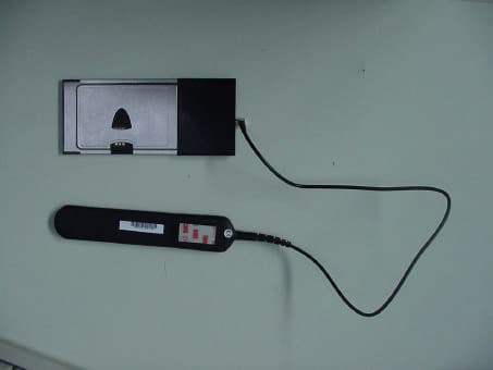
Click to zoom
Application Details
- Equipment Class
- PCB - PCS Licensed Transmitter
- Date of Grant
- Jun 02, 2005
- Application Purpose
- Original Equipment
- Date of Application
- Jun 02, 2005
- Equipment Note
- PCMCIA card for UMTS/GPRS/GSM
- Frequency Range
- 824.20000000 - 848.80000000
- Company
- Option (Crescent NV)
- Country
- Belgium
Documents & Files
Document Text
Text extracted from the exhibit documents filed with the FCC. Open a document above to read the original.
Users Manual
OPTION WIRELESS Technologies, Kolonel Begaultlaan 45, B-3012 Leuven Tel +32 16 317 411 Fax +32 16 207 164 http://www.option.com Option Confidential Integration manual: Option Globetrotter Data Card Integration Manual Author: Roeland Timmermans Version: 2 Creation Date: May 26, 2005 Page: 1 of 4 Option Confidential: This document is Option Confidential - it may not be duplicated, neither distributed externally without prior and written permission of Option NV. About this document Overview and Purpose This document describes the manner in which a Option Globetrotter datacard can be integrated into a third party device and what conditions must be fulfilled in doing so. Confidentiality All data and information contained or disclosed by this document is confidential and proprietary of Option NV, and all rights therein are expressly reserved. By accepting this document, the recipient agrees that this information is held in confidence and in trust and will not be used, copied, reproduced in whole or in part, nor its contents revealed in any manner to others without prior and written permission of Option NV Version History Date Release Version Author(s) Revision(s) Remarks Phase 25/05/05 1.0 – Draft 1 RoelT Initial version 1.0.0 26/05/05 1.0 - Draft 2 BrunoM Corrections 1.0.0 Integration Manual Author: Roeland Timmermans Version: 2 Creation Date: May 26, 2005 Page: 2 of 4 Option Confidential: This document is Option Confidential - it may not be duplicated, neither distributed externally without prior and written permission of Option NV. Table of contents 1. Introduction............................................................................................................... 3 2. PCMCIA Interface.................................................................................................... 3 3. RF Connector............................................................................................................ 4 4. SAR Safety measures................................................................................................ 4 5. FCC label................................................................................................................... 4 Integration Manual Author: Roeland Timmermans Version: 2 Creation Date: May 26, 2005 Page: 3 of 4 Option Confidential: This document is Option Confidential - it may not be duplicated, neither distributed externally without prior and written permission of Option NV. 1. Introduction When integrating the Option Globetrotter 3G Quad Slim it is necessary to pay attention to all technical aspects described in this document. Using these guidelines is mandatory to provide certainty of the correct performance of the card in its new environment. 2. PCMCIA Interface The third party device shall be equipped with a fully compliant PCMCIA Interface to which the Option data card can be connected in order to communicate with the other parts integrated into the new device. Higher layer communication with the option datacard is only possible using at- commands described in 3GPP specifications TS 27.007 and special developed option proprietary at-commands. Using these commands specific characteristics of the datacard can be altered to obtain the desired functionality. Integration Manual Author: Roeland Timmermans Version: 2 Creation Date: May 26, 2005 Page: 4 of 4 Option Confidential: This document is Option Confidential - it may not be duplicated, neither distributed externally without prior and written permission of Option NV. 3. RF Connector When it is desired to use the datacard in conducted mode it is necessary to use the output RF connector. To connect to the output use the R299.792.000 RF connector (manufacturer Radiall). 4. SAR Safety measures Concerning specific safety guidelines we advise the end-user to keep a minimum distance of 20 cm between himself and the device. 5. FCC label When the card is integrated into the new equipment it must still have the original FCC-ID label developed by Option N.V. If the FCC ID in not visible when the card is installed inside another device, then the outside of the complete device into which the card is installed must also display a label referring to the enclosed card. This exterior label can use wording such as the following: “Contains FCC ID NCMOGL3QS”.
Cover Letter(s)
Option nv sa | Kolonel Begaultlaan 45 | B-3012 Leuven Belgium | www.option.com T +32 16 317 411 | F +32 16 207 164 | H.R.L./R.C.L. 68114 | BTW/TVA BE 429.375.448 Option N.V. Kolonel Begaultlaan 45 3012 Leuven Belgium To Whom This May Concern Commercial Power of Attorney Commercial Power of Attorney for the license / registration of GlobeTrotter 3G Quad Slim in several countries. The company 7 layers AG, 40880 Ratingen, Germany, has been contracted by Option N.V. to obtain approvals for the following electronic components, manufactured and/or released by Option N.V. : GlobeTrotter 3G Quad Slim : GSM/GPRS/UMTS Quad Band PC DATA CARD Unless future correspondence from Option N.V. directs otherwise, please extend your full cooperation to 7 layers AG regarding matters to the above mentioned products for the period beginning May 1 st 2005 through January 1 st 2006. Stefan Lodeweyckx System & Product Quality Team Leader Leuven, May 26th 2005
Cover Letter(s)
Option nv sa | Kolonel Begaultlaan 45 | B-3012 Leuven Belgium | www.option.com T +32 16 317 411 | F +32 16 207 164 | H.R.L./R.C.L. 68114 | BTW/TVA BE 429.375.448 Declaration of Product Identity Product Name: Globetrotter 3G Quad Slim Model Name: Globetrotter 3G Quad Slim Manufacturer: Option N.V. We, option N.V., declare on our sole responsibility that the product Globetrotter 3G Quad Slim (NCMOGL3QS) is in all relevant parts identical to the product Globetrotter 3G Quad (NCMOGL3Q) which is already certified. The model Ricola Quad Lite Slim differs to model Ricola Quad Lite in following points: 1.) The Internal antenna is removed 2.) The Globetrotter 3G Quad Slim will be using a different FCC-ID label (NCMOGL3QS) Please attached photos from both models where the differences are shown. Globetrotter 3G Quad Slim (without antenna): Option nv sa | Kolonel Begaultlaan 45 | B-3012 Leuven Belgium | www.option.com T +32 16 317 411 | F +32 16 207 164 | H.R.L./R.C.L. 68114 | BTW/TVA BE 429.375.448 Globetrotter 3G Quad (with antenna): Globetrotter Table of standards: - R&TTE Direcctive 1999/5/EC - EN 301 489 -1/-7 - EN 60950-1 - EN 50360 - 3GPP TS 51.010-1 Applicable GCF version: GCF-CC V3.16 Company Option N.V. Street Kolonel Begaultlaan 45 Address 3012 Wilsele Country Belgium Responsible person sign: _________________ Stefan Lodeweyckx System & Product Quality Team Leader
Cover Letter(s)
RE: CONFIDENTIALITY REQUEST FOR ‘GlobeTrotter 3G Quad Slim’, FCC-ID: NCMOGL3QS To Whom It May Concern: This letter serves as an official request for confidentiality under the FCC Rule Section 0.459. We have requested that the schematic diagrams, Parts list and Block diagrams required to be submitted with this application be withheld from public review. The reason for this request is that these documents are company proprietary information that should never get into the possession of competitors, which would be harmful for our business. Do not hesitate to contact me if you have any additional questions. Thank you very much. Leuven, 27 January 2005 Sytem & Product Quality Team Leader Stefan Lodeweyckx Option N.V. Kolonel Begaultlaan 45 3012 Leuven Belgium Option nv sa | Kolonel Begaultlaan 45 | B-3012 Leuven Belgium | www.option.com T +32 16 317 411 | F +32 16 207 164 | H.R.L./R.C.L. 68114 | BTW/TVA BE 429.375.448
External Photos
Globetrotter 3G Quad Slim: 5. Foto Report Picture1EUT (top side): Picture2EUT (bottom side): Page 15 of 17Testreport Reference: 4_OPTI_0505_ERF_FCCb
ID Label/Location Info
Kol. Begaultlaan 45 - B3012 Leuven Belgium Part Number:Rev : Part Name: Page: Size:Scale: Drawn: Project: Date: Approved: QUALCOMM 3G CDMA QL1LBL-21622_1 Model: GT 3G Quad Slim Designed in E.U. by Option Datacard: UMTS/GPRS 1.Overall dimensions: 62,4mm x 40,6mm / Radius Corners: 1,6mm Same outline as CL1LBL-20037_2 2.To be supplied in the format shown, on reels, copy position 2, internal core dia 38mm 3.Quantity per roll: 1000 or max o/d 4” 4.Each roll to be packed in bubble wrap and sealed in a polythene bag containing no other shedding material. Reels then to be packed in a box, each box to contain 4 reels. The outside of the box to be clearly labelled with the following information: - Option Part number - Quantity in box - Date produced 5.Liner to be 6.Label thickness: 50 44mm wide. Vertical gap between labels 4.275mm. μm max. 7.Label to be silver and suitable for thermal transfer printing. 8.Label to be printed with artwork_art.* 9.Printing be resistant to rubbing and alcohol cleaning. 10. Raw material: FLEXcon THERMLfilm MM 200 satin silver TC-715 L-344 40 White Glassine 11. Artwork use black 32364 12. To be used with print ribbon: Armor AXR7+ or equivalent. QL1LBL-21622_1 DATE APPROVED ISSUEDDESCRIPTION REV ECP 1 Derived from RQ1LBL-20730_1 RQL manuflabelTS 1891 25/05/05 07000700 1/1 A4 1:1 Thomas STEVENS 23/05/05 QL1LBL-21622 SLIM Manufacturing Label Guysol RICOLA QUAD LITE 1 Outline Artwork FCC ID NCMOGL3QS FF T ested to Comply With FCC Standards For Home or Office Use
Internal Photos
Globetrotter 3G Quad Slim: 1 Option nv sa | Kolonel Begaultlaan 45 | B-3012 Leuven Belgium | www.option.com T +32 16 317 411 | F +32 16 207 164 | H.R.L./R.C.L. 68114 | BTW/TVA BE 429.375.448
Operational Description
features >Multimode UMTS/GPRS/GSM card for use on 850/900/1800/1900/2100 networks >Provides UMTS High-speed data (up to 384 kbps) connectivity to mobile users >Provides GPRS/GSM data (up to 85.6 kbps) connectivity >Provides transparent handover between UMTS and GSM/GPRS networks >Compatible with Microsoft Windows and nearly all popular laptop PCs , equipped with Type II PCMCIA compliant 32-bit CardBus Interface >Supports IPSec client software for end to end secure corporate data exchange and synchronisation over VPN hardware specifications >Card Type : .Extended Type II PCMCIA compliant .32-bit CardBus PC Card Interface >External Interfaces : Miniature External Antenna Connection, two colour status LED >SIM card interface : Low profile, 6 contact connector on bottom side of card. Compliant with 3GPP 31.101 and 31.102 >Memory : Flash technology for easy upgrade >Environmental operating temperature : 0 to +55ºC Kolonel Begaultlaan 45 |3012 Leuven Belgium |T +32 16 317 411|F +32 16 207 164|www.option.com|[email protected] multimode|3g umts|gprs|pc data card globetrotter3g quad specifications >UMTS Air Interface (EMEA) : .EMEA : 2100 MHz .UE Power Class 3 (+24 dBm) .High Speed packet-switched data : >384/64, 128/128, 64/64,...PS RAB (DL/UL) >Support for simultaneous multiple calls >Support for UMTS QoS traffic classes >Support for PPP, IP transparent and non-transparent modes .Circuit-switched data : 64 and 14.4 kbps >UMTS Air Interface (North America): .USA: 850/1900 MHz .UE Power Class 3 (+24 dBm) .High Speed packet-switched data: >384/64, 128/128, 64/64,...PS RAB (DL/UL)) >Support for simultaneous multiple calls >Support for UMTS QoS traffic classes > Support for PPP, IP transparent and non-transparent modes .Circuit-switched data : 64 and 14.4 kbps >GSM/GPRS Air Interface .850/900/1800/1900 MHz .UE Power Class 1 (1W) for 1800MHz bands and Power Class 4 (2W) for 900 Mhz bands .Packet-switched data : >Multislot Class 10 GSM 05.0 (4 slots Rx, 2 slots Tx, 5 max active) >GPRS Class B Type 1 MT >Support for GPRS QoS traffic classes .Circuit-switched data : 14.4 and 9.6 kbps >Terminal Equipment Interfaces : .Operating Systems: Windows 98SE/ME/2000/XP (please contact us regarding support for other Operating Systems) .AT Interface 3GPP TS27.005, ATD*99# support, unimodem extensions .Standard modem emulation for compatibility with standard terminal programs/dialers and for use with proprietary operating systems .network coverage reports during data calls .separate diagnostics port .separate PCSC port for SIM access to enable EAP-SIM authentication in WLAN applications
RF Exposure Info
RF exposure requirements - FCC ID: Dear Examiner, The maximum measured power output is 1445 mW (31,6 dBm), the maximum antenna gain is 0,75. The maximum permissible exposure is defined in 47 CFR 1.1310 with 1 mW/cm². The Transmitter is using indoor antennas that operate at 20 cm or more from nearby persons. The maximum permitted level is calculated using the general equation: S = P*G / 4πR² P = 1445 mW, G = 0,75 R = 20 cm π = 3,1416 Solving for S, the power density at 20 cm is 0,216 mW/cm². So the 1 mW/cm² limit is kept. Please contact us if you have any additional questions. Best Regards 7 layers AG i.A. T. Hoell
Test Report
7 layers AG Aufsichtsratsvorsitzenderh Registergerichth registered in: Borsigstrasse 11 Chairman of the Supervisory Board: Düsseldorf, HRB 44096 40880 Ratingen, Germany Michael Abels USt-IdNr h VAT Nr: Phone: +49 (0) 2102 749 0 Vorstandh Board: DE 203159652 Fax: +49 (0) 2102 749 350 Dr. Hans-Jürgen Meckelburg www.7Layers.com René Schildknecht InterLab is a registered trademark of 7 layers AG FCC Measurement/Technical Report on PCMCIA card Globetrotter 3G Quad Slim Report Reference: 4_OPTI_0505_ERF_FCCa Test Laboratory: 7 layers AG Borsigstrasse 11 40880 Ratingen Germany email: [email protected] DAT-P-192/99-01 Note: The following test results relate only to the devices specified in this document. This report shall not be reproduced in parts without the written approval of the testing laboratory. Testreport Reference: 4_OPTI_0505_ERF_FCCa Page 2 of 18 Table of Contents 0 Summary 3 0.1 Technical Report Summary 3 0.2 Measurement Summary 4 1 Administrative Data 5 1.1 Testing Laboratory 5 1.2 Project Data 5 1.3 Applicant Data 5 1.4 Manufacturer Data 5 2 Testobject Data 6 2.1 General EUT Description 6 2.2 EUT Main components 7 2.3 Ancillary Equipment 7 2.4 EUT Setups 7 2.5 Operating Modes 8 3 Test Results 9 3.1 Field strength of spurious radiation 9 4 Test Equipment 12 5 Photo Report 15 6 Setup Drawings 18 Testreport Reference: 4_OPTI_0505_ERF_FCCa Page 3 of 18 0 Summary 0.1 Technical Report Summary Type of Authorization Certification for a GSM cellular radiotelephone device Applicable FCC Rules Prepared in accordance with the requirements of FCC Rules and Regulations as listed in 47 CFR Ch.1 Parts 0 to 19 and Parts 20 to 69 (10-1-01 Edition). The following subparts are applicable to the results in this test report. Part 2 Subpart J - Equipment Authorization Procedures, Certification § 2.1046 Measurement required: RF power output § 2.1049 Measurement required: Occupied bandwidth § 2.1051 Measurement required: Spurious emissions at antenna terminals § 2.1053 Measurement required: Field strength of spurious emission § 2.1055 Measurement required: Frequency stability § 2.1057 Frequency spectrum to be investigated Part 22 Subpart H – Cellular Radiotelephone Service § 22.355 Frequency tolerance § 22.913 Effective radiated power limits § 22.917 Emission limitations for cellular Summary Test The EUT complied with all performed tests as listed in chapter 0.2 Measurement Summary. Testreport Reference: 4_OPTI_0505_ERF_FCCa Page 5 of 18 1 Administrative Data 1.1 Testing Laboratory Company Name: 7 Layers AG Address Borsigstr. 11 40880 Ratingen Germany This facility has been fully described in a report submitted to the FCC and accepted under the registration number 96716 . The test facility is also accredited by the following accreditation organisation: - Deutscher Akkreditierungs Rat DAR-Registration no. TTI-P-G 178/99 Responsible for Accreditation Scope: Dipl.-Ing. Bernhard Retka Dipl.-Ing. Arndt Stöcker Dipl.-Ing. Thomas Hoell Report Template Version: 2005-02-01 1.2 Project Data Responsible for testing and report: Dipl.-Ing. Robert Machulec Receipt of EUT: 2005-05-19 Date of Test(s): 2005-05-24 Date of Report: 2005-05-25 1.3 Applicant Data Company Name: Option International NV SA Address: Kolonel Begaultlaan 45 3012 Leuven Belgium Contact Person: Mr. Stefan Lodeweyckx 1.4 Manufacturer Data Company Name: please see applicant data Address: Contact Person: Testreport Reference: 4_OPTI_0505_ERF_FCCa Page 6 of 18 2 Testobject Data 2.1 General EUT Description Equipment under PCMCIA card Type Designation: Globetrotter 3G Quad Slim Kind of Device: (optional) GSM 850/900/1800/1900; UMTS; GPRS Voltage Type: DC (powered by PC) Nominal Voltage: 5.0 V Maximum Voltage: - Minimum Voltage: - General product description: The Equipment Under Test (EUT) is a GSM 850/900/1800/1900; UMTS; GPRS phone. In GSM 850 mode the card operates in channel blocks A and B from 824.2 MHz (lowest channel = 128) to 848.8 MHz (highest channel = 251). The EUT provides the following ports: Ports antenna connector enclosure external antenna The main components of the EUT are listed and described in Chapter 2.2 Testreport Reference: 4_OPTI_0505_ERF_FCCa Page 7 of 18 2.2 EUT Main components Type, S/N, Short Descriptions etc. used in this Test Report Short Description Equipment under Test Type Designation Serial No. HW Status SW Status Date of Receipt EUT A (Code: 37s41a01) Globetrotter 3G Quad Slim GSM Phone GSM Phone QL4A4BC02S 4.0 1.5.5 2005-05-19 Remark: EUT A is equipped with a permanent antenna connector. EUT B (Code: 37s41a01) external antenna Test sample 1 - - 2005-05-19 Remark: EUT B is external antenna. NOTE: The short description is used to simplify the identification of the EUT in this test report. 2.3 Ancillary Equipment For the purposes of this test report, ancillary equipment is defined as equipment which is used in conjunction with the EUT to provide operational and control features to the EUT. It is necessary to configure the system in a typical fashion, as a customer would normally use it. But nevertheless Ancillary Equipment can influence the test results. Short Description Equipment under Test Type Designation HW Status SW Status Serial no. FCC ID AE1 Laptop Compaq NC6000 - OP-system Windows XP - – 2.4 EUT Setups This chapter describes the combination of EUT's and ancillary equipment used for testing. Setup No. Combination of EUTs Description 37s41a01 EUT A + EUT B + AE1 Testreport Reference: 4_OPTI_0505_ERF_FCCa Page 8 of 18 2.5 Operating Modes This chapter describes the operating modes of the EUT's used for testing. Op. Mode Description of Operating Modes Remarks op-mode 1 Call established on Traffic Channel (TCH) 128, Carrier Frequency 824.2 MHz 128 is the lowest channel op-mode 2 Call established on Traffic Channel (TCH) 190, Carrier Frequency 836.6 MHz 190 is a mid channel of the full GSM band op-mode 3 Call established on Traffic Channel (TCH) 251, Carrier Frequency 848.8 MHz 251 is the highest channel Testreport Referen…
Text truncated - open the document above for the full version.
Test Report
FCC Measurement/Technical Report on 4_OPTI_0505_ERF_FCCb 7 Layers AG Borsigstr. 11 40880 Ratingen Germany Note: The following test results relate only to the devices specified in this document. This report shall not be reproduced in parts without the written approval of the testing laboratory. PCMCIA card Globetrotter 3G Quad Slim 7 layers AG, Borsigstrasse 11 40880 Ratingen, Germany Phone: +49 (0) 2102 749 0 Fax: +49 (0) 2102 749 350 http://www.7Layers.com Aufsichtsratsvorsitzender - Chairman of the Supervisory Board: Michael Abels Vorstand - Board of Directors: Dr. Hans-Jürgen Meckelburg René Schildknecht Registergericht - registered in: Düsseldorf, HRB 44096 USt-IdNr VAT Nr: DE 203159652 Report Reference: DAT-P-192/99-01 Test Laboratory (Headquarter): Interlab is a registered trademark of 7 layers AG Table of Contents 0. Summary 0.1 Technical Report Summary 0.2 Measurement Summary 1. Administrative Data 1.1 Testing Laboratory 1.2 Project Data 1.3 Applicant Data 1.4 Manufacturer Data 2. Testobject Data 2.1 General EUT Description 2.2 EUT Main Components 2.3 Ancillary Equipment 2.4 EUT Setups 2.5 Operating Modes 3. Test Results 3.1 Field Strength of Spurious Radiation 4. Testequipment 5. Foto Report 6. Setup Drawings 3 3 4 5 5 5 5 5 6 6 7 7 7 7 8 8 12 15 17 Page 2 of 17 Testreport Reference: 4_OPTI_0505_ERF_FCCb 0 Summary 0.1 Technical Report Summary Type of Authorization Certification for a broadband PCS device Applicable FCC Rules Prepared in accordance with the requirements of FCC Rules and Regulations as listed in 47 CFR Ch.1 Parts 0 to 19 and Parts 20 to 69 (10-1-98 Edition). The following subparts are applicable to the results in this test report. Part 2 Subpart J - Equipment Authorization Procedures, Certification § 2.1046 Measurement required: RF power output § 2.1049 Measurement required: Occupied bandwidth § 2.1051 Measurement required: Spurious emissions at antenna terminals § 2.1053 Measurement required: Field strength of spurious emission § 2.1055 Measurement required: Frequency stability § 2.1057 Frequency spectrum to be investigated Part 24 Subpart E - Broadband PCS § 24.232 Power and antenna height limits § 24.235 Frequency stability § 24.238 Emission limits Summary Test Results: The EUT complied with all performed tests as listed in chapter 0.2 Measurement Summary. Page 3 of 17 Testreport Reference: 4_OPTI_0505_ERF_FCCb 1. Administrative Data 1.1 Testing Laboratory Company Name: Address: The test facility is also accredited by the following accreditation organisation: Responsible for Accreditation Scope: 7 Layers AG Borsigstr. 11 40880 Ratingen Germany DAR-Registration no. TTI-P-G 178/99 Dipl.-Ing Bernhard Retka Dipl.-Ing Arndt Stöcker Dipl.-Ing Thomas Hoell This facility has been fully described in a report submitted to the FCC and accepted under the registration number 96716 . - Deutscher Akkreditierungs Rat 2005-05-19 Dipl.-Ing. Robert Machulec 2005-05-25 2005-05-24 Responsible for testing and report Receipt of EUT: Date of Test(s): Date of Report: 1.2 Project Data Option International NV SA Mr. Stefan Lodeweyckx Kolonel Begaultlaan 45 3012 Leuven Belgium please see Applicant data 1.4 Manufacturer Data Company Name: Address: Contact Person: Company Name: Address: Contact Person: 1.3 Applicant Data Page 5 of 17 Testreport Reference: 4_OPTI_0505_ERF_FCCb 2. Testobject Data Type Designation: Kind of Device: (optional) Voltage Type: Nominal Voltage: Equipment under Test: Globetrotter 3G Quad Slim GSM 850/900/1800/1900; UMTS; GPRS PCMCIA card DC (powered by PC) 5 V Ports 2.1 General EUT Description General product description: The Equipment Under Test (EUT) is a GSM 850/900/1800/1900; UMTS; GPRS phone. In the PCS1900 mode the card operates in blocks A through F from 1850,2 MHz (lowest channel = 512) to 1909,8 MHz (highest channel = 810). The EUT provides the following ports: Maximum Voltage: Minimum Voltage: - - external antenna antenna connector enclosure The main components of EUT are listed and described in Chapter 2.2 Page 6 of 17 Testreport Reference: 4_OPTI_0505_ERF_FCCb Short Description Equipment under Test Type Designation 2.2 EUT Main components: Type, S/N, Short Descriptions etc. used in this Test Report HW StatusSW StatusSerial No.Date of Receipt 4.01.5.5QL4A4BC02S2005-05-19 PCMCIA cardGlobetrotter 3G Quad Slim EUT A (Code: 37s41a01) EUT A is equipped with a permanent antenna connector. --Test sample 12005-05-19 external antennaantennaEUT B (Code: 37s41a01) EUT B is an external antenna. NOTE: The short description is used to simplify the identification of the EUT in this test report 2.3 Ancillary Equipment Short Description Equipment under Test Type DesignationHW StatusSW StatusSerial No.FCC Id For the purposes of this test report, ancillary equipment is defined as equipment which is used in conjunction with the EUT to provide operational and control features to the EUT. It is necessary to configure the system in a typical fashion, as a customer would normally use it. But never the less Ancillary Equipment can influence the test results. AE 1Compaq nc6000PC (Laptop)-OP-system Windows XP -- Setup No.Combination of EUTsDescription 2.4 EUT Setups This chapter describes the combination of EUT's and ancillary equipment used for testing. 37s41a01 EUT A + EUT B + AE1 Op. Mode Description of Operating Modes Remarks 2.5 Operating Modes This chapter describes the operating modes of the EUT's used for testing. op-mode 1Call established on Traffic Channel (TCH) 512, Carrier Frequency 1850,2 MHz 512 is the lowest channel op-mode 2Call established on Traffic Channel (TCH) 661, Carrier Frequency 1880 MHz 661 is a mid channel of the full PCS band (blocks A to F) op-mode 3Call established on Traffic Channel (TCH) 810, Carrier Frequency 1909,8 MHz 810 is the highest channel Page 7 of 17Testreport Reference: 4_OPTI_0505_ERF_FCCb 3. Test Results Field strength of spurious radiation StandardFCC Part 24, Subpart E The test was performed according to:FCC §2.1053 1) The mobile statio…
Text truncated - open the document above for the full version.
Test Report
F2015 Revision: A 01-08-03 GlobeSurfer Antenna Measurement Author: Xiaohai Shen Type: Issued Revision log: 1 File name: GS-RF-TN-010-V1- AntennaMeasurement.doc Date: 29-04-2005 Revision Log: Revision Author Date Comment 1 Xiaohai Shen 29-04-05 Initial draft, radiated gain, VSWR and isolation of GlobeSurfer antennas were measured in Satimo Paris and Option Leuven on 27/04/2005. F2015 Revision: A Page 2 of 21 01-08-03 GS-RF-TN-010-V1-AntennaMeasurement.doc 1 Table of contents 1 Table of contents....................2 2 Introduction...............................2 3 Test setup and DUT...................................3 3.1 Measurement system............................3 3.2 DUT...................................................4 3.3 Orientation during the radiation test......5 4 Test result..............................................6 4.1 Measured VSWR and isolation...............6 4.1.1 Measured VSWR.............................6 4.1.2 Measured isolation among antennas..8 4.2 Measured radiated gain......................10 4.2.1 Measured gain of GSM/UMTS antenna10 4.2.2 Measured gain of WLAN antenna 1...14 4.2.3 Measured gain of WLAN antenna 2...17 4.2.4 Measured gain listed in tables........20 5 Conclusion...........................................21 2 Introduction For Option GlobeSurfer project, the antennas of Possio PX40 were measured in Option Leuven and in Satimo Paris. In this report, all the measured results are presented. F2015 Revision: A Page 3 of 21 01-08-03 GS-RF-TN-010-V1-AntennaMeasurement.doc 3 Test setup and DUT 3.1 Measurement system The radiated gain is measured in Satimo Paris with the Stargate 64 system as shown in the picture. Fig. 1. Satimo Stargate 64 measurement system. F2015 Revision: A Page 4 of 21 01-08-03 GS-RF-TN-010-V1-AntennaMeasurement.doc 3.2 DUT Three printed antennas (two WLAN antennas and one GSM/UMTS antenna) on Possio PX40 PCB are measured. In Fig. 2, these three antennas are illustrated. WLAN antenna 1 WLAN antenna 2 GSM/UMTS antenna Fig. 2. Three printed antennas on Possio PX40 PCB. F2015 Revision: A Page 5 of 21 01-08-03 GS-RF-TN-010-V1-AntennaMeasurement.doc 3.3 Orientation during the radiation test Fig. 3. Orientation during the radiation measurement. The orientation and the coordinate system are illustrated in Fig. 3. With this 3D coordinate system, XOY plane is the azimuth plane with θ = 90°, XOZ plane is the elevation plane with φ = 0°, and YOZ plane is the elevation plane with φ = 90°. The measured radiated power in these three main planes will be presented. F2015 Revision: A Page 6 of 21 01-08-03 GS-RF-TN-010-V1-AntennaMeasurement.doc 4 Test result 4.1 Measured VSWR and isolation 4.1.1 Measured VSWR Fig. 4. Measured VSWR of WLAN antenna 1. F2015 Revision: A Page 7 of 21 01-08-03 GS-RF-TN-010-V1-AntennaMeasurement.doc Fig. 5. Measured VSWR of WLAN antenna 2. Fig. 6. Measured VSWR of GSM/UMTS antenna. F2015 Revision: A Page 8 of 21 01-08-03 GS-RF-TN-010-V1-AntennaMeasurement.doc Table 1: Measured VSWR of the three printed antennas Measured VSWR of Frequency (MHz) GSM/UMTS antenna WLAN antenna 1 WLAN antenna2 824 2.55 Not used Not used 880 2.18 Not used Not used 960 2.24 Not used Not used 1710 1.65 Not used Not used 2170 1.64 Not used Not used 2400 Not used 2.62 2.48 2500 Not used 2.33 2.06 4.1.2 Measured isolation among antennas Fig. 7. Measured isolation between the GSM/UMTS antenna and the WLAN antenna 2. F2015 Revision: A Page 9 of 21 01-08-03 GS-RF-TN-010-V1-AntennaMeasurement.doc Fig. 7. Measured isolation between the WLAN antenna 1 and the WLAN antenna 2. Table 2: Measured isolation among the antennas on PX40 PCB Measured isolation (in dB) between Frequency (MHz) GSM/UMTS antenna and WLAN antenna 1 WLAN antenna 1 and WLAN antenna 2 824 28.39 52.38 880 25.57 47.95 960 25.46 38.89 1710 12.25 16.74 2170 17.64 10.64 2400 17.75 13.73 2500 18.26 14.41 F2015 Revision: A Page 10 of 21 01-08-03 GS-RF-TN-010-V1-AntennaMeasurement.doc 4.2 Measured radiated gain 4.2.1 Measured gain of GSM/UMTS antenna Fig. 8. Measured 3D gain of Possio GSM/UMTS antenna at 2140MHz.
Test Report
F2015 Revision: A Page 11 of 21 01-08-03 GS-RF-TN-010-V1-AntennaMeasurement.doc Fig. 9. Measured gain of Possio GSM/UMTS antenna in XOY plane. F2015 Revision: A Page 12 of 21 01-08-03 GS-RF-TN-010-V1-AntennaMeasurement.doc Fig. 10. Measured gain of Possio GSM/UMTS antenna in XOZ plane. F2015 Revision: A Page 13 of 21 01-08-03 GS-RF-TN-010-V1-AntennaMeasurement.doc Fig. 11. Measured gain of Possio GSM/UMTS antenna in YOZ plane. F2015 Revision: A Page 14 of 21 01-08-03 GS-RF-TN-010-V1-AntennaMeasurement.doc 4.2.2 Measured gain of WLAN antenna 1 Fig. 12. Measured gain of Possio WLAN antenna 1in XOY plane. F2015 Revision: A Page 15 of 21 01-08-03 GS-RF-TN-010-V1-AntennaMeasurement.doc Fig. 13. Measured gain of Possio WLAN antenna 1 in XOZ plane. F2015 Revision: A Page 16 of 21 01-08-03 GS-RF-TN-010-V1-AntennaMeasurement.doc Fig. 14. Measured gain of Possio WLAN antenna 1 in YOZ plane. F2015 Revision: A Page 17 of 21 01-08-03 GS-RF-TN-010-V1-AntennaMeasurement.doc 4.2.3 Measured gain of WLAN antenna 2 Fig. 15. Measured gain of Possio WLAN antenna 2 in XOY plane. F2015 Revision: A Page 18 of 21 01-08-03 GS-RF-TN-010-V1-AntennaMeasurement.doc Fig. 16. Measured gain of Possio WLAN antenna 2 in XOZ plane. F2015 Revision: A Page 19 of 21 01-08-03 GS-RF-TN-010-V1-AntennaMea…
Text truncated - open the document above for the full version.
Contact Information
Applicant
Joost van der Velden(CEO)
Technical Contact
Option International NVStefan Lodeweyckx
[email protected]+32 16 317
Kolonel Begaultlaan · Leuven · Belgium
Non-Technical Contact
Option International NVBruno Meeus
[email protected]+32 16 317
Test Firm
7layers AGRobert Machulec
Technical Specifications
| # | Rule Parts | Frequency Range | Power Output | Emission | Tolerance |
|---|---|---|---|---|---|
| 2 | 22H | 824.2 MHz - 848.8 MHz | 1.45 W | 300KGXW | 2.5 ppm |
Other Applications from Option (Crescent NV)

NCM-CG2132
Sep 21, 2022LoRaWAN 86x/9xx Expansion card
Equipment Class
DTS - Digital Transmission System
NCM-WT500
Jun 06, 2021Water and Temperature Sensor
Equipment Class
DSS - Part 15 Spread Spectrum Transmitter
NCMOCG2101
Feb 27, 2013CloudGate 802.11abgn Wireless LAN Card
Equipment Class
NII - Unlicensed National Information Infrastructure TX
NCMOMO6792
Feb 24, 2013GTM679W
Equipment Class
JBP - Part 15 Class B Computing Device PeripheralNCMOGI0644
Jun 17, 2012GSM/UMTS/WLAN USB Modem GI0644
Equipment Class
PCB - PCS Licensed Transmitter