NCMOGS0361Wireless Router
Option (Crescent NV)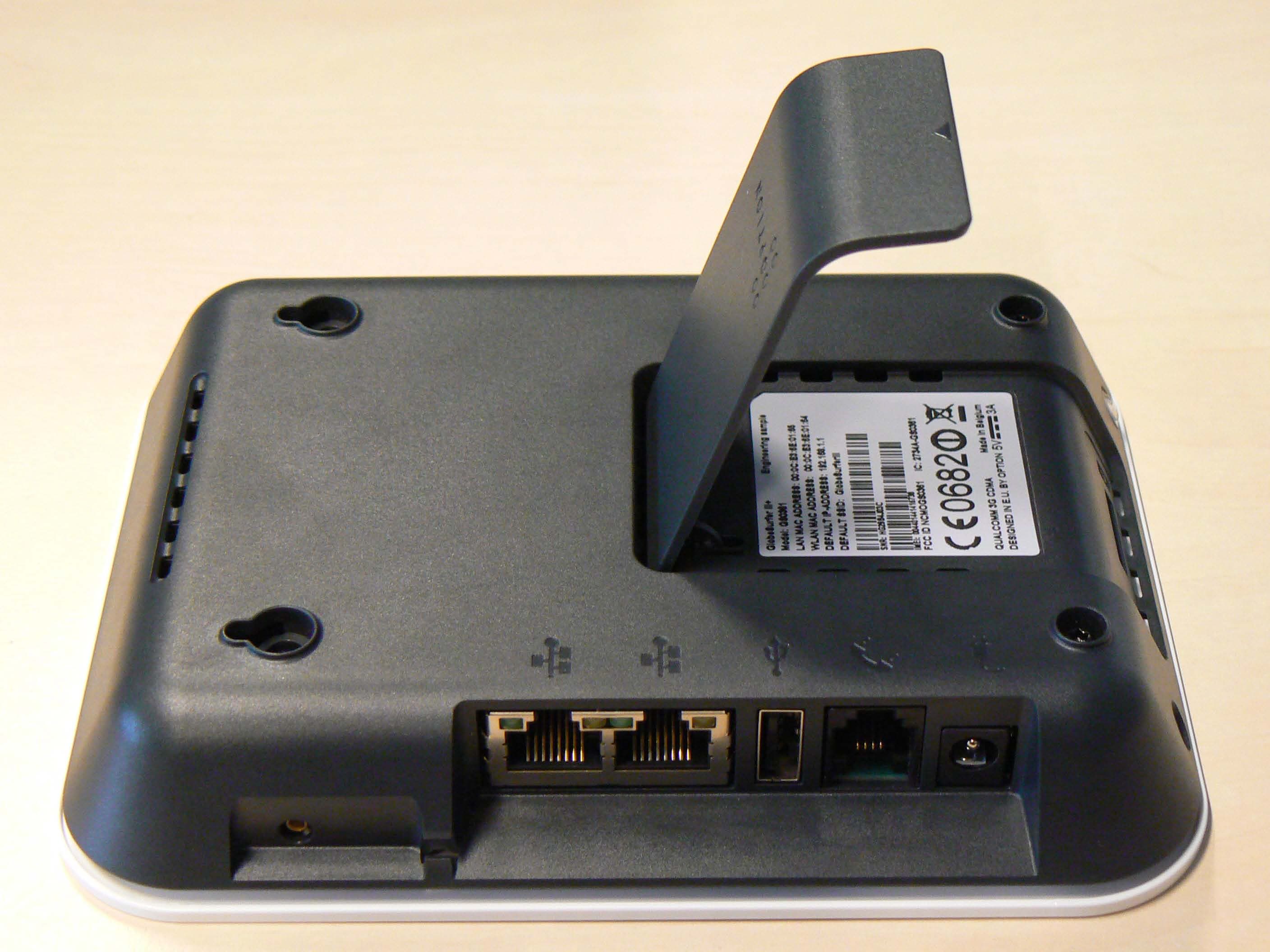
Click to zoom
Application Details
- Equipment Class
- DTS - Digital Transmission System
- Date of Grant
- Jul 11, 2011
- Application Purpose
- Original Equipment
- Date of Application
- Jul 11, 2011
- Equipment Note
- Wireless Router
- Frequency Range
- 2412.00000000 - 2462.00000000
- Company
- Option (Crescent NV)
- Country
- Belgium
Documents & Files
Document Text
Text extracted from the exhibit documents filed with the FCC. Open a document above to read the original.
Users Manual
2 Welcome to GlobeSurfer III+ Within minutes, you can connect to your mobile network and use a wireless connection to the Internet through the mobile network. GlobeSurfer III+ is compatible with GSM and 3G mobile networks and supports GPRS, EDGE, UMTS, HSDPA and HSUPA technologies (WWAN). With ‘Receive Diversity’ on all the high as well as low bands, the signal strength and overall WWAN reception is unparalleled. Tip: To achieve the best possible reception, check the signal strength using the web interface. You may find that placing the unit near a window provides the best reception. Simple set-up GlobeSurfer III+ provides you with a quick installation and set-up that gets you easily and quickly connected to the Internet. You can use any internet browser (e.g. Internet Explorer 7.0 or Firefox 2.5) and most operating systems including Windows, Macintosh and Linux. The ‘Quick Setup Wizard’ introduces you to the basic settings that need to be configured for use with the mobile network. Once you have configured, you can review and enable customized wireless security settings. Instant protection Your GlobeSurfer III+ supports Network Address Translation (NAT). This network service hides the computers in your network so they cannot be found or directly accessed from outside your network. A firewall is also included which, by default, blocks incoming traffic and allows outgoing traffic. Additional security GlobeSurfer III+ supports both Wired Equivalent Privacy (WEP) and Wi-Fi Protected Access (WPA and WPA2) to protect your network data. Security logs keep you aware of potential security risks and intrusion attempts. You can view logs online or via email. Stay in touch You can use GlobeSurfer III+ to send and receive SMS text messages. The telephone LED on the front panel lets you know when a new SMS arrives. If you have installed the “Notifier” software application, then you will also receive a desktop alert indicating the receipt of text messages. The “Notifier” software will also allow you to connect directly to the browser page that handles SMS text messages. You can use GlobeSurfer III+ to make mobile phone calls. Should you miss a call an LED indicates this. If you have installed the “Notifier” software application, then you will also receive a desktop alert indicating the receipt of telephone calls, as well as missed calls. The “Notifier” software will also allow you to connect directly to the browser page that handles telephone calls. Important note To protect your network from unauthorized access, and to make it more difficult for hackers to analyze your data, please configure the WLAN security settings and enable WEP, WPA or WPA2 encryption on your GlobeSurfer III+. 3 Copyright © 2010, Option Information about Option GlobeSurfer III+ may change without prior notice. Information published in this user guide is accurate at the time of publication. Although all reasonable care is taken during the creation of this user guide Option is not liable toward persons or organizations for losses or damages caused either directly or indirectly due to instructions contained in this user guide. All brands and registered brands are property of their respective owners. Services may be changed, added or deleted. For the newest firmware version for your GlobeSurfer III+ visit http://www.option.com WARNING The GlobeSurfer III+ is intended for use only when powered by the external power supply shipped with it or via a replacement power supply available from Option. The use of any other power supply may invalidate regulatory approval of this equipment. Refer to the table below for applicable power supplies. The exception to this rule is vehicle installation. The GlobeSurfer III+ can be used in vehicle installations and is compliant with the Automotive EMC Directive 2004/104/EC when used with a compliant DC to DC converter. It is the owner’s responsibility to ensure the DC to DC converter is compatible with GlobeSurfer III+ and that it is compliant with the Automotive EMC Directive 2004/104/EC. GlobeSurfer III+ is intended for indoor use only and its interconnection points shall not be connected outside of any premises (i.e. the outside of any building or vehicle). Refer to the table below for each interconnection point found in this user instruction. GlobeSurfer III+ is regarded a class III equipment where protection against electric shock is provided by means of power supplied from SELV circuit i.e. external power supply and does not generate hazardous voltages within itself. The GlobeSurfer III+ is intended to be used with a POTS (telephone) and LAN cable with maximum length of 3 m. If a longer LAN cable is used it must be shielded in order not to invalidate regulatory approval. Applicable power supplies Power supply Manufacturer Model GS3 AC/DC adapter PHIHONG Equipment interconnection points Interconnection Category Type DC input connector SELV 5.5/1.2mm DC jack 4 SIM card connector SELV SIM type (ISO7816) External antenna connector SELV MC-CARD type LAN connector SELV RJ45 Telephone connector TNV2 RJ11 Rated Input Voltage Maximum Input Voltage 5 VDC SELV interconnections must only be connected to other equipment that complies with requirements of SELV-circuits as defined in EN60950 directive. TNV2 interconnections must only be connected to other equipment that complies with requirements of TNV2-circuits as defined in EN60950 directive. 5 Contents Welcome to GlobeSurfer III+ ......................................................................................................... 2 Contents ...................................................................................................................................................5 Your GlobeSurfer III+ ..................................................................................................................... 8 Buttons and connections .........................................................................................................…
Text truncated - open the document above for the full version.
Test Report
CETECOM ICT Services GmbH Untertürkheimer Straße 6-10 . D-66117 Saarbrücken Phone: +49 (0) 681-598-0 Fax:-9075 RSC-Laboratory 2008-08-22 Page 1 of 82 Accredited testing-laboratory DAR registration number: DAT-P-176/94-D1 Federal Motor Transport Authority (KBA) DAR registration number: KBA-P 00070-97 Recognized by the Federal Communications Commission Anechoic chamber registration no.: 90462 (FCC) Anechoic chamber registration no.: 3463A-1 (IC) Certification ID: DE 0001 Accreditation ID: DE 0002 Accredited Bluetooth ® Test Facility (BQTF) The Bluetooth word mark and logos are owned by the Bluetooth SIG, Inc. and any use of such marks by Cetecom ICT is under license Test report no. : 1-0345-07-03/08 Type identification : GlobeSurfer 311 Applicant : Option N.V. FCC ID : NCMOGS0311 IC Certification No : -/- Test standards : 47 CFR Part 15 CETECOM ICT Services GmbH Test report no.: 1-0345-07-03/08 2008-08-22 Page 2 of 82 Table of contents 1 G e n e r a l i n f o r m a t i o n . . . . . . . . . . . . . . . . . . . . . . . . . . . . . . . .. . . . . . . . . . . . . . . . . . . . . . . . . . . . . . . . . . . . . . . . . . . . . . . . . . .. . . . . . . . . . . . . . . 3 1.1 Notes ...................................................................................................................................................................3 1.2 Testing laboratory ...............................................................................................................................................4 1.3 Details of applicant .............................................................................................................................................4 1.4 Application details ..............................................................................................................................................4 2 T e s t s t a n d a r d / s : . . . . . . . . . . . . . . . . . . . . . . . . . . . . . . . . . . .. . . . . . . . . . . . . . . . . . . . . . . . . . . . . . . . . . . . . . . . . . . . . . . . . . .. . . . . . . . . . . . . . . . . . 5 3 T e c h n i c a l t e s t s . . . . . . . . . . . . . . . . . . . . . . . . . . . . . . . . . . . .. . . . . . . . . . . . . . . . . . . . . . . . . . . . . . . . . . . . . . . . . . . . . . . . . . .. . . . . . . . . . . . . . . . . . . 6 3.1 Details of manufacturer.......................................................................................................................................6 3.1.1 Test item......................................................................................................................................................6 3.1.2 EUT operating modes..................................................................................................................................7 3.1.3 Extreme conditions testing values ...............................................................................................................7 4 S u m m a r y o f M e a s u r e m e n t R e s u l t s a n d l i s t o f a l l p e r fo r m e d t e s t c a s e s . . . . . . . . . . . . . . . . . . . . . . . . . 8 5 R F m e a s u r e m e n t t e s t i n g . . . . . . . . . . . . . . . . . . . . . . . . . . . . .. . . . . . . . . . . . . . . . . . . . . . . . . . . . . . . . . . . . . . . . . . . . . . . . . . .. . . . . . . . . . . . 9 5.1 Description of test set-up ....................................................................................................................................9 5.1.1 Radiated measurements...............................................................................................................................9 5.1.2 Conducted measurements............................................................................................................................9 5.2 Referenced Documents .....................................................................................................................................10 5.3 Additional comments ........................................................................................................................................10 5.4 Antenna gain .....................................................................................................................................................10 5.5 Peak Power Spectral density (digitally modulated systems) §15.247(e)...........................................................11 5.6 Spectrum Bandwidth of a DSSS System / 6 dB Bandwidth §15.247(a)(2).......................................................15 5.7 Spectrum Bandwidth of a DSSS System / 20 dB Bandwidth............................................................................19 5.8 Maximum output power (conducted) §15.247 (b)(3)........................................................................................23 5.9 Max. peak output power (radiated) §15.247 (b)(3) ...........................................................................................25 5.10 Band-edge compliance of conducted emissions §15.247 (d) ........................................................................26 5.11 Band-edge compliance of radiated emissions §15.205 .................................................................................28 5.12 Spurious Emissions - conducted (Transmitter) §15.247 (c) ..........................................................................32 5.13 Spurious Emissions - radiated (Transmitter) §15.209 ...................................................................................42 5.14 Spurious Emissions - radiated (Receiver) §15.109 / 209 ..............................................................................60 5.15 Spurious Emissions - radiated <30 MHz §15.209.........................................................................................64 5.16 Conducted Emissions <30 MHz §15.107/207...................................................................................…
Text truncated - open the document above for the full version.
Test Setup Photos
CETECOM ICT Services GmbH Test report no.: 1-0345-07-03/08 2008-08-22 Page 72 of 82 7 Ph otog ra ph s of th e Test S et-up Photo 1: (radiated) Photo 2: (radiated) CETECOM ICT Services GmbH Test report no.: 1-0345-07-03/08 2008-08-22 Page 73 of 82 Photo 3: (radiated) Photo 4: (conducted)
Contact Information
Applicant
Joost van der Velden(CEO)
Test Firm
cetecom advanced GmbHGerald Schmidt
Technical Specifications
| # | Rule Parts | Frequency Range | Power Output |
|---|---|---|---|
| 1 | 15C | 2.41 GHz - 2.46 GHz | 55.00 mW |
Other Applications from Option (Crescent NV)

NCM-CG2132
Sep 21, 2022LoRaWAN 86x/9xx Expansion card
Equipment Class
DTS - Digital Transmission System
NCM-WT500
Jun 06, 2021Water and Temperature Sensor
Equipment Class
DSS - Part 15 Spread Spectrum Transmitter
NCMOCG2101
Feb 27, 2013CloudGate 802.11abgn Wireless LAN Card
Equipment Class
NII - Unlicensed National Information Infrastructure TX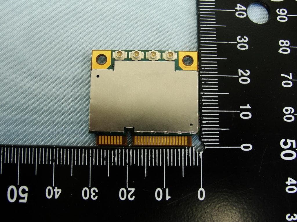
NCMOMO6792
Feb 24, 2013GTM679W
Equipment Class
JBP - Part 15 Class B Computing Device PeripheralNCMOGI0644
Jun 17, 2012GSM/UMTS/WLAN USB Modem GI0644
Equipment Class
PCB - PCS Licensed Transmitter