NCMOGTM351-EMini PCI Card for GSM/GPRS/UMTS/HSDPA
Option (Crescent NV)
Click to zoom
Application Details
- Equipment Class
- PCB - PCS Licensed Transmitter
- Date of Grant
- Dec 28, 2005
- Application Purpose
- Original Equipment
- Date of Application
- Dec 28, 2005
- Equipment Note
- Mini PCI Card for GSM/GPRS/UMTS/HSDPA
- Frequency Range
- 824.20000000 - 848.80000000
- Company
- Option (Crescent NV)
- Country
- Belgium
Documents & Files
Document Text
Text extracted from the exhibit documents filed with the FCC. Open a document above to read the original.
Users Manual
--------- - - -- - - - - - - - - - - - - - - - - - - - - - - - --- globetrotter mobilitymanager manual in cn / d / e / f / i / nl / p on cd Warning ! Do not insert the card ! Registering your card is of great value to you. As soon as you register, you will qualify for: > Validation of warranty, which includes repair or replacement if faulty > After-sales customer care > Advanced bulletins on product updates and software upgrades During the installation process, you will have the possibility to register online or via e-mail. You may also register on-line at: http://www.option.com/registration/4_3_registration.shtml 3 register with option do not print this page Register with Option3 Introduction4 System Requirements5 Installation8 Getting Started10 Trouble shooting33 Safety Information34 contents Congratulations on your purchase of the Option GlobeTrotter card. GlobeTrotter together with the GlobeTrotter Mobility Manager software is the ultimate high performance solution for providing mobile wireless connectivity to Laptops and Notebooks. The GlobeTrotter solution enables users to browse the Internet, send and receive e-Mails, send and receive SMS text messages and all with SIM management seamlessly integrated with Microsoft Outlook™. The technology in your Option GlobeTrotter card supports real time remote connectivity and is ideal for the synchronization of mobile devices with the office or home computer. GlobeTrotter is designed to support IPsec client software providing secure remote IP mobile access to corporate networks. This guide describes how to install the GlobeTrotter Mobility Manager (GTMM) software on your PC and how to start using it. For more detailed information, consult the GTMM Online Help Guide. Contents of the sales package In the sales package, you will find the following items: > Option GlobeTrotter card > A CD-Rom containing the software To overcome any installation and usage barriers and to enhance the user experience, the following documentation is also included: > This Quick Start Guide, which gives the installation of the GlobeTrotter Mobility Manager Software in a limited number of steps, and assists the user in making his/her first data call > Online User Manual, which describes a number of common usage scenarios. The online User manual can be accessed at all times through the Help menu of the software. introduction 4 The GlobeTrotter Mobility Manager software requires: Processor > Client (a computer not working in a server capacity): Min. 90-megahertz (MHz) Intel Pentium II-class processor or higher > Server (a computer working in a server capacity): Min.133-MHz Intel Pentium- class processor Operating System > Windows XP Professional > Windows XP Home Edition > Windows 2000 > Windows ME > Windows 98SE Memory > Client: 64 megabytes (MB) of RAM, 96 MB recommended > Server: 128 MB of RAM, 256 MB recommended Hard Disk Min. 40 MB for installation of SW & Drivers Display 800 x 600 or higher-resolution display with 256 colors Input Device Microsoft mouse or compatible pointing device system requirements (minimum requirements) 5 Communications software When you run the installation program, the following programs will be installed on your computer: > Windows GlobeTrotter device drivers > The GlobeTrotter Mobility Manager The GlobeTrotter Mobility Manager The GlobeTrotter Mobility Manager GTMM simplifies SMS messaging and the configuration of GPRS settings for applications such as downloading e-mail or browsing the Internet. It also gives the possibility to manage a WLAN connection. The GTMMapplication incorporates a powerful SMS editor and a viewer for reading SMS messages. Incoming and outgoing messages are listed in Outlook™-style directories. The Setup pagegives users a quick and easy way to set up any type of connection (GSM, GPRS or 3G). The WLAN pagegives users a quick and easy way to scan and connect on a WLAN network. system requirements (minimum requirements) 7 Other requirements > Microsoft Internet Explorer 6.00 or later > The latest Windows service packs and critical updates from the Windows Update site. > The target system may not have any version of the ‘Funk Odyssey’ WLAN client installed, otherwise the installation will fail Please refer to the GlobeTrotter datacard Product Sheet for datacard system requirements. Network services To use your Option GlobeTrotter card, you must first activate an account with a mobile phone Service Provider and have received a Subscriber Identity Module (SIM) card. Often the GlobeTrotter is supplied as a package with an airtime agreement. If you do not already have an airtime agreement, please ask your supplier about obtaining one for a compatible network. Please refer to the GlobeTrotter datacard Product Sheet which will detail the types of network and services it is compatible with. Some service providers may not provide all communications services. Contact your service provider for further information about the availability and details of the services in your home network. Additional information may be required from your service provider to activate the data functionality of the Option GlobeTrotter card such as: > User Name - if applicable > Password - if applicable > Access Point Name (APN) > IP Address - if not dynamic > DNS Address - if not dynamic system requirements (minimum requirements) 6 10.At the end of the installation you will have to reboot the PC and if you have selected automatic start up, the GTMM application will start up after the reboot. 11. Insert the Option GlobeTrotter card into the PCMCIA slot of your PC. 12. Wait until the system has recognized the card. 13. You will now be asked to register the product. Registration is required to benefit from the warranty and customer care. By connecting to the Internet you can register online immediately athttp://www.option.com/registration/4_3_registration.shtml Choose Cancelif you want to register later. You will be able to start the registration from the h…
Text truncated - open the document above for the full version.
Block Diagram
PCI ECPRESS MINICARD CONNECTOR P o w e r R a i l s V H O S T V D D _ P , V _ R F R X 1 , V _ R F T X , V _ T C X O , V R E G _ S Y N T H U S I M P o w e r R a i l s U S B 1 . 1 L D O T i t l e : C o b r a B l o c k D i a g r a m D a t e : J U N E 0 2 n d , 2 0 0 5 A u t h o r : P . S c h r i j v e r s M C P M i r r o r b i t 2 5 6 M b i t F L A S H A s y n c / P a g e / B u r s t 1 2 8 M b i t c e l l u l a r S R A M A s y n c / P a g e / B u r s t A d d r e s s A [ 0 . . 2 2 ] D a t a [ 0 . . 1 5 ] C o n t r o l B u s V D D _ E V D D _ C , V D D _ E 3 2 k H z P M 6 6 5 0 U S B 1 . 1 S B b u s P o w e r R a i l s L D O B u c k r e g u l a t o r s U S B T r a n s c e i v e r V D D _ P , V D D _ A , V R E G _ R U I M V _ R F R X 1 , V _ R F T X , V _ T C X O , V R E G _ S Y N T H M U X A N A _ I N U S I M l e v e l t r a n s l a t o r U S I M T C X O C o n t r o l l e r 1 9 . 2 M H z f r o m R F V H O S T 3 V 3 4 8 M H z V R E G _ R U I M L E D _ W W A N L E D _ W W A N R T R 6 2 5 0 R F T r a n s c e i v e r I C O - P L L 8 6 9 – 1 8 1 0 M H z B P F B P F B P F B P F P A A ntenna Switch Module U M T S D U A L P A G S M 8 5 0 R x G S M 9 0 0 R x G S M 1 9 0 0 R x G S M 1 8 0 0 R x R F L 6 2 0 2 R F L N A B P F R F R 6 2 0 2 R F R e c e i v e r U M T S R x V C O 1 4 0 8 – 1 7 3 8 M H z 1 9 . 2 M H z V C T C X O D u p l e x e r Isolator Isolator D u p l e x e r P A U M T S B P F Hirose 0.5mm pitch connector V R E G _ R U I M A M U X _ O U T V D D _ P , V D D _ A , V D D _ C , V D D _ E Debug Connec tor M S M 6 2 7 5 W C D M A / H S D P A G S M / G P R S / E D G E 1 9 . 2 M H z T o P o w e r M a n a g e m e n t C h i p D i g i t a l C o n t r o l s i g n a l s ( G P I O ) U M T S R x I / Q U M T S T x I / Q S B b u s A R M _ J T A G
Cover Letter(s)
Option N.V. Kolonel Begaultlaan 45 3012 Leuven Belgium To Whom This May Concern Commercial Power of Attorney Commercial Power of Attorney for the license / registration of GlobeTrotter Module GTM351E in several countries. The company 7 layers AG, 40880 Ratingen, Germany, has been contracted by Option N.V. to obtain approvals for the following electronic components, manufactured and/or released by Option N.V. : GlobeTrotter Module GTM351E : GSM/GPRS/UMTS/HSDPA Quad Band PCI Express Mini Card Unless future correspondence from Option N.V. directs otherwise, please extend your full cooperation to 7 layers AG regarding matters to the above mentioned products for the period beginning December 1 st 2005 through July 1 st 2006. Bernard Schaballie Vice President Engineering Leuven, dec. 16 2005 Option nv sa | Kolonel Begaultlaan 45 | B-3012 Leuven Belgium | www.option.com T +32 16 317 411 | F +32 16 207 164 | H.R.L./R.C.L. 68114 | BTW/TVA BE 429.375.448
Cover Letter(s)
Option N.V. Kolonel Begaultlaan 45 3012 Leuven Belgium RE: CONFIDENTIALITY REQUEST FOR ‘GlobeTrotter Module GTM351E’, FCC-ID: NCMOGTM351-E To Whom It May Concern: This letter serves as an official request for confidentiality under the FCC Rule Section 0.459. We have requested that the schematic diagrams, Parts list, Block diagrams and Integration manual required to be submitted with this application be withheld from public review. The reason for this request is that these documents are company proprietary information that should never get into the possession of competitors, which would be harmful for our business. Do not hesitate to contact me if you have any additional questions. Thank you very much. Leuven, 16 december 2005 Vice President Engineering Bernard Schaballie Option N.V. Kolonel Begaultlaan 45 3012 Leuven Belgium Option nv sa | Kolonel Begaultlaan 45 | B-3012 Leuven Belgium | www.option.com T +32 16 317 411 | F +32 16 207 164 | H.R.L./R.C.L. 68114 | BTW/TVA BE 429.375.448
ID Label/Location Info
Kol. Begaultlaan 45 - B3012 Leuven Belgium Part Number:Rev : Part Name: Page: Size:Scale: Drawn: Project: Date: Approved: QUALCOMM 3G CDMA CO1LBL-21860_1 Model: GT M351 E Made in Ireland by Option Designed in E.U. by Option QUALCOMM 3G CDMA CO1LBL-21860_1 Model: GT M351 E Made in Ireland by Option Designed in E.U. by Option IMEI : 4256231313666 SNR : 4256231313 1.Overall dimensions: 26.5mm x 25mm 2.To be supplied in the format shown, on reels, copy position 2, internal core dia 38mm 3.Quantity per roll: 1000 or max o/d 4” 4.Each roll to be packed in bubble wrap and sealed in a polythene bag containing no other shedding material. Reels then to be packed in a box, each box to contain 4 reels. The outside of the box to be clearly labeled with the following information: - Option Part number - Quantity in box - Date produced 5.Liner to be 6.Label thickness: 50 TBDmm wide. Vertical gap between labels TBDmm. μm max. 7.Label to be silver and suitable for thermal transfer printing. 8.Label to be printed with artwork_art.* 9.Printing be resistant to rubbing and alcohol cleaning. 10. Raw material: FLEXcon THERMLfilm MM 200 satin silver TC-712 L-344 40 White Glassine 11. Artwork use black 32364 12. To be used with print ribbon: Armor AXR7+ or equivalent. CO1LBL-21860_1 DATE APPROVED ISSUEDDESCRIPTION REV ECP 1 First draftTS 2411 21/09/05 FF T ested to Comply With FCC Standards F or Home or Office Use FCC ID NCMOGTM351-E FF T ested to Comply With FCC Standards F or Home or Office Use FCC ID NCMOGTM351-E 1/1 A4 1:1 CO1LBL-21860 Manufacturing Label Cobra EMEA Thomas STEVENS COBRA 1 21/09/05 ArtworkOutlinePrinted Example 25.0 20.0 16.0 26.5 5.3
Operational Description
GTM351E GTM351E The GTM351E PCI Express Mini Card module provides Wireless WAN function- ality to any device with a compatible PCI Express Mini Card slot. In particular, the GTM351E is the solution of choice for embedding HSDPA, UMTS and EDGE connectivity into laptops devices. It supports HSDPA 1.8 Mbps, UMTS WCDMA in the 2100 MHz band and EDGE/GPRS Quad band (850/900/1800/1900 MHz), thereby ensuring worldwide operation. “Connect anytime, anywhere” HSDPA | 3G UMTS | EDGE | GPRS embedded wireless module features > Multimode UMTS/EDGE/GPRS/GSM card with HSDPA 1.8 Mbps support > Provides HSDPA High-speed data (up to 1.8 Mbps downlink and up to 384kbps uplink) connectivity on HSDPA-equipped networks > Provides UMTS High-speed data (up to 384 kbps) connectivity on UMTS networks > Provides EDGE/GPRS/GSM data (up to 247 kbps) connectivity > Low power dissipation for easy embedding > Transparent handover between UMTS and GSM/E-GPRS networks > The design Benefits from Option’s extensive experience in data PC-cards > Tested on infrastructures and networks worldwide > Flexible driver design providing both NDIS and modem modes for easy integration into dashboard applications > Future proofing through Flash Memory technology > Connector for external antenna > Connector for external SIM/UICC holder Kolonel Begaultlaan 45 | 3012 Leuven Belgium | T +32 16 317 411 | F +32 16 207 164 | www.option.com GTM351E specifications > HSDPA 1.8Mbps . UE category 12, QPSK, 1.8 Mbps peak rate . PS RAB (DL: up to 1.8 Mbps; UL: up to 384 kbps) > WCDMA . FDD 2100 MHz . Power Class 3 (+24dBm) . 384 kbps class modem operation in both uplink and downlink . Supports UL and DL Compressed Modes . Supports Circuit and Packet-Switched Data > E-GPRS . 850/900/1800/1900 MHz . GSM Power Class 4 (2W) for 850/900 bands, GSM . Power Class 1 (1W) for 1800/1900 bands . EDGE class E2 (+27 dBm in 850/900 bands, +26 dBm in 1800/1900 bands) . GPRS/EGPRS Multislot Class 10 (4 slots Rx, 2 slots Tx, 5 max active) . GPRS/EGPRS Class B Type 1 MT . GPRS CS1-CS4; EGPRS MCS1-MCS9 . Circuit Switched Data: 14.4 and 9.6 kbps terminal equipment interfaces > USB 1.1 signaling > AT interface with standard modem emulation > NDIS and Modem interface drivers > NDIS required for OS compliance and future proofing (Longhorn) > Modem interface required to allow 3rd party application support > EAP-SIM / EAP-AKA support > Operating Systems supported: . Windows 2000/XP Home/ XP Pro/ Vista . Tablet/XP Pro/Mac OS X Tiger regulatory & certifications > R&TTE, GCF for WCDMA > R&TTE, GCF, FCC, PTCRB for EGPRS power Requirements > Vcc 3.3V +/- 9% > Peak Icc 2750 mA with max supply droop 50 mA > Average Icc 1000 mA As part of their continual product improvement process Option reserve the right to alter the specifications for the product detailed here. HSDPA | 3G UMTS | EDGE | GPRS P icture of embedded wireless module with cover shielding removed. P icture of embedded wireless module with cover shielding removed.
Test Report
7 layers AG Aufsichtsratsvorsitzenderh Registergerichth registered in: Borsigstrasse 11 Chairman of the Supervisory Board: Düsseldorf, HRB 44096 40880 Ratingen, Germany Markus Becker USt-IdNr h VAT Nr: Phone: +49 (0) 2102 749 0 Vorstandh Board: DE 203159652 Fax: +49 (0) 2102 749 350 Dr. Hans-Jürgen Meckelburg www.7Layers.com René Schildknecht InterLab is a registered trademark of 7 layers AG FCC Measurement/Technical Report on GSM module GTM351E Report Reference: 4_Opti_0405_UMTS_FCCc Test Laboratory: 7 layers AG Borsigstrasse 11 40880 Ratingen Germany email: [email protected] DAT-P-192/99-01 Note: The following test results relate only to the devices specified in this document. This report shall not be reproduced in parts without the written approval of the testing laboratory. Test report Reference: 4_Opti_0405_UMTS_FCCc Page 2 of 53 Table of Contents 0 Summary 3 0.1 Technical Report Summary 3 0.2 Measurement Summary 4 1 Administrative Data 6 1.1 Testing Laboratory 6 1.2 Project Data 6 1.3 Applicant Data 6 1.4 Manufacturer Data 6 2 Testobject Data 7 2.1 General EUT Description 7 2.2 EUT Main components 8 2.3 Ancillary Equipment 8 2.4 EUT Setups 8 2.5 Operating Modes 9 3 Test Results 10 3.1 RF Power Output 10 3.2 Frequency stability 14 3.3 Spurious emissions at antenna terminals 18 3.4 Field strength of spurious radiation 22 3.5 Emission and Occupied Bandwidth 26 3.6 Mobile emissions in base frequency range 30 4 Test Equipment 33 5 Photo Report 36 6 Setup Drawings 40 7 Annex 42 Measurement Plots Test report Reference: 4_Opti_0405_UMTS_FCCc Page 3 of 53 0 Summary 0.1 Technical Report Summary Type of Authorization Certification for a GSM cellular radiotelephone device Applicable FCC Rules Prepared in accordance with the requirements of FCC Rules and Regulations as listed in 47 CFR Ch.1 Parts 0 to 19 and Parts 20 to 69 (10-1-04 Edition). The following subparts are applicable to the results in this test report. Part 2 Subpart J - Equipment Authorization Procedures, Certification § 2.1046 Measurement required: RF power output § 2.1049 Measurement required: Occupied bandwidth § 2.1051 Measurement required: Spurious emissions at antenna terminals § 2.1053 Measurement required: Field strength of spurious radiation § 2.1055 Measurement required: Frequency stability § 2.1057 Frequency spectrum to be investigated Part 22 Subpart C – Operational and Technical Requirements § 22.355 Frequency tolerance Subpart H – Cellular Radiotelephone Service § 22.913 Effective radiated power limits § 22.917 Emission limitations for cellular equipment Summary Test The EUT complied with all performed tests as listed in chapter 0.2 Measurement Summary. Test report Reference: 4_Opti_0405_UMTS_FCCc Page 4 of 53 0.2 Measurement Summary RF Power Output The measurement was performed according to FCC §2.1046 10-01-2004 OP-Mode Setup Port Final Result op-mode 1 Setup_c01 antenna connector passed op-mode 2 Setup_c01 antenna connector passed op-mode 3 Setup_c01 antenna connector passed op-mode 4 Setup_c01 antenna connector passed op-mode 5 Setup_c01 antenna connector passed op-mode 6 Setup_c01 antenna connector passed Frequency stability The measurement was performed according to FCC §2.1055 10-01-2004 OP-Mode Setup Port Final Result op-mode 2 Setup_a01 antenna connector passed op-mode 5 Setup_b01 antenna connector passed Spurious emissions at antenna terminals The measurement was performed according to FCC §2.1051 10-01-2004 OP-Mode Setup Port Final Result op-mode 1 Setup_c01 antenna connector passed op-mode 2 Setup_c01 antenna connector passed op-mode 3 Setup_c01 antenna connector passed op-mode 4 Setup_c01 antenna connector passed op-mode 5 Setup_c01 antenna connector passed op-mode 6 Setup_c01 antenna connector passed Field strength of spurious radiation The measurement was performed according to FCC §2.1053 10-01-2004 OP-Mode Setup Port Final Result op-mode 1 Setup_a02 enclosure passed op-mode 2 Setup_a02 enclosure passed op-mode 3 Setup_a02 enclosure passed op-mode 4 Setup_a02 antenna connector passed op-mode 5 Setup_a02 antenna connector passed op-mode 6 Setup_a02 antenna connector passed Emission and Occupied Bandwidth The measurement was performed according to FCC §2.1049 10-01-2004 OP-Mode Setup Port Final Result op-mode 1 Setup_a01 antenna connector passed op-mode 2 Setup_a01 antenna connector passed op-mode 3 Setup_a01 antenna connector passed op-mode 4 Setup_a01 antenna connector passed op-mode 5 Setup_a01 antenna connector passed op-mode 6 Setup_a01 antenna connector passed Test report Reference: 4_Opti_0405_UMTS_FCCc Page 6 of 53 1 Administrative Data 1.1 Testing Laboratory Company Name: 7 Layers AG Address Borsigstr. 11 40880 Ratingen Germany This facility has been fully described in a report submitted to the FCC and accepted under the registration number 96716 . The test facility is also accredited by the following accreditation organisation: - DEUT’scher Akkreditierungs Rat DAR-Registration no. DAT-P-192/99-01 Responsible for Accreditation Scope: Dipl.-Ing. Bernhard Retka Dipl.-Ing. Arndt Stöcker Dipl.-Ing. Thomas Hoell Report Template Version: 2005-10-10 1.2 Project Data Responsible for testing and report: Dipl.-Ing. Robert Machulec Receipt of EUT: 2005-10-07 Date of Test(s): 2005-10-07 to 2005-11-25 Date of Report: 2005-12-27 1.3 Applicant Data Company Name: Option International NV SA Address: Kolonel Begaultlaan 45 3012 Leuven Belgium Contact Person: Mr. Stefan Lodeweyckx 1.4 Manufacturer Data Company Name: please see applicant data Address: Contact Person: Test report Reference: 4_Opti_0405_UMTS_FCCc Page 7 of 53 2 Testobject Data 2.1 General EUT Description Equipment under GSM module Type Designation: GTM351E Kind of Device: (optional) GSM 850/900/1800/1900 with EDGE Voltage Type: DC Nominal Voltage: 3.0 V Maximum Voltage: 3.5 V Minimum Voltage: 3.5 V General product description: The Equipment Under Test (EUT) is a GSM 850/900/1800/1900 with EDGE module. In GSM 850 mode the EUT operates in channel block…
Text truncated - open the document above for the full version.
Test Report
7 layers AG Aufsichtsratsvorsitzenderh Registergerichth registered in: Borsigstrasse 11 Chairman of the Supervisory Board: Düsseldorf, HRB 44096 40880 Ratingen, Germany Markus Becker USt-IdNr h VAT Nr: Phone: +49 (0) 2102 749 0 Vorstandh Board: DE 203159652 Fax: +49 (0) 2102 749 350 Dr. Hans-Jürgen Meckelburg www.7Layers.com René Schildknecht InterLab is a registered trademark of 7 layers AG FCC Measurement/Technical Report on GSM module GTM351E Report Reference: 4_Opti_0405_UMTS_FCCd Test Laboratory: 7 layers AG Borsigstrasse 11 40880 Ratingen Germany email: [email protected] DAT-P-192/99-01 Note: The following test results relate only to the devices specified in this document. This report shall not be reproduced in parts without the written approval of the testing laboratory. Test report Reference: 4_Opti_0405_UMTS_FCCd Page 2 of 49 Table of Contents 0 Summary 3 0.1 Technical Report Summary 3 0.2 Measurement Summary 4 1 Administrative Data 5 1.1 Testing Laboratory 5 1.2 Project Data 5 1.3 Applicant Data 5 1.4 Manufacturer Data 5 2 Testobject Data 6 2.1 General EUT Description 6 2.2 EUT Main components 7 2.3 Ancillary Equipment 7 2.4 EUT Setups 7 2.5 Operating Modes 8 3 Test Results 9 3.1 RF Power Output 9 3.2 Frequency stability 13 3.3 Spurious emissions at antenna terminals 17 3.4 Field strength of spurious radiation 21 3.5 Emission and Occupied Bandwidth 25 4 Test Equipment 29 5 Photo Report 32 6 Setup Drawings 36 7 Annex 38 Measurement Plots Test report Reference: 4_Opti_0405_UMTS_FCCd Page 3 of 49 0 Summary 0.1 Technical Report Summary Type of Authorization Certification for a GSM cellular radiotelephone device Applicable FCC Rules Prepared in accordance with the requirements of FCC Rules and Regulations as listed in 47 CFR Ch.1 Parts 0 to 19 and Parts 20 to 69 (10-1-04 Edition). The following subparts are applicable to the results in this test report. Part 2 Subpart J - Equipment Authorization Procedures, Certification § 2.1046 Measurement required: RF power output § 2.1049 Measurement required: Occupied bandwidth § 2.1051 Measurement required: Spurious emissions at antenna terminals § 2.1053 Measurement required: Field strength of spurious radiation § 2.1055 Measurement required: Frequency stability § 2.1057 Frequency spectrum to be investigated Part 24 Subpart E - Broadband PCS § 24.232 Power and antenna height limits § 24.235 Frequency stability § 24.236 Field strength limits § 24.238 Emission limitations for Broadband PCS equipment Summary Test Results: The EUT complied with all performed tests as listed in chapter 0.2 Measurement Summary. Test report Reference: 4_Opti_0405_UMTS_FCCd Page 5 of 49 1 Administrative Data 1.1 Testing Laboratory Company Name: 7 Layers AG Address Borsigstr. 11 40880 Ratingen Germany This facility has been fully described in a report submitted to the FCC and accepted under the registration number 96716 . The test facility is also accredited by the following accreditation organisation: - DEUT’scher Akkreditierungs Rat DAR-Registration no. DAT-P-192/99-01 Responsible for Accreditation Scope: Dipl.-Ing. Bernhard Retka Dipl.-Ing. Arndt Stöcker Dipl.-Ing. Thomas Hoell Report Template Version: 2005-10-10 1.2 Project Data Responsible for testing and report: Dipl.-Ing. Robert Machulec Receipt of EUT: 2005-10-07 Date of Test(s): 2005-10-07 to 2005-11-25 Date of Report: 2005-12-27 1.3 Applicant Data Company Name: Option International NV SA Address: Kolonel Begaultlaan 45 3012 Leuven Belgium Contact Person: Mr. Stefan Lodeweyckx 1.4 Manufacturer Data Company Name: please see applicant data Address: Contact Person: Test report Reference: 4_Opti_0405_UMTS_FCCd Page 6 of 49 2 Testobject Data 2.1 General EUT Description Equipment under GSM module Type Designation: GTM351E Kind of Device: (optional) GSM 850/900/1800/1900 with EDGE Voltage Type: DC Nominal Voltage: 3.0 V Maximum Voltage: 3.5 V Minimum Voltage: 3.5 V General product description: The Equipment Under Test (EUT) is a GSM 850/900/1800/1900 with EDGE module. In PCS1900 mode the EUT operates in blocks A through F from 1850,2 MHz (lowest channel = 512) to 1909,8 MHz (highest channel = 810). The EUT provides the following ports: Ports antenna connector enclosure mini PCMCIA slot The main components of the EUT are listed and described in Chapter 2.2 Test report Reference: 4_Opti_0405_UMTS_FCCd Page 7 of 49 2.2 EUT Main components Type, S/N, Short Descriptions etc. used in this Test Report Short Description Equipment under Test Type Designation Serial No. HW Status SW Status Date of Receipt EUT A (Code: 37060b01) GSM module GTM351 Test sample 1 1.0 3.4.0 2005-10-07 Remark: EUT A is equipped with an antenna connector. EUT B (Code: 37060c01) GSM module GTM351 Test sample 2 1.0 3.4.0 2005-10-07 Remark: EUT A is equipped with an antenna connector. NOTE: The short description is used to simplify the identification of the EUT in this test report. 2.3 Ancillary Equipment For the purposes of this test report, ancillary equipment is defined as equipment which is used in conjunction with the EUT to provide operational and control features to the EUT. It is necessary to configure the system in a typical fashion, as a customer would normally use it. But nevertheless Ancillary Equipment can influence the test results. Short Description Equipment under Test Type Designation HW Status SW Status Serial no. FCC ID AE1 Cradle - - - - – AE2 Antenna (gain=2dBi) OI-ANT-EX-3G - - - – AE3 Cradle - - - - – AE4 Cradle - - - - – NOTE: The cradle AE1 was modified with additional capacitors. 2.4 EUT Setups This chapter describes the combination of EUT's and ancillary equipment used for testing. Setup No. Combination of EUT’s Description setup_a01 EUT A + AE1 setup for conducted tests setup_b01 EUT A + AE3 setup for conducted tests setup_c01 EUT B + AE4 setup for conducted tests setup_a02 EUT A + AE3 + AE2 setup for radiated spurious emissions tests Test report Reference: 4_Opti_0405_UMTS_FCCd Page 8 of 49 2.5 Operating Modes This chapter …
Text truncated - open the document above for the full version.
Test Report
Annex I: band edge compliance Measurement plots Test report reference: 4_Opti_0405_UMTS_FCCa Date: 2005-12-08 Annex I: band edge compliance - Measurement plots Test report reference: 4_Opti_0405_UMTS_FCCa Page 2 of 5 A Offset 26 dB LVL Ref 20 dBmAtt 30 dB * * RBW 3 kHz VBW 3 kHz SWT 190 ms Center823.5 MHzSpan1 MHz100 kHz/ 1 PK MAXH PRN -80 -70 -60 -50 -40 -30 -20 -10 0 10 20 1 Marker 1 [T1 ] -14.34 dB m 823.996000000 MHz D1 -13 dBm Date: 24.NOV.2005 17:37:21 Test: band edge compliance , Channel 128, PCS Annex I: band edge compliance - Measurement plots Test report reference: 4_Opti_0405_UMTS_FCCa Page 3 of 5 A Offset 26 dB LVL Ref 20 dBmAtt 30 dB * * RBW 3 kHz VBW 3 kHz SWT 190 ms Center823.5 MHzSpan1 MHz100 kHz/ 1 PK MAXH PRN -80 -70 -60 -50 -40 -30 -20 -10 0 10 20 1 Marker 1 [T1 ] -21.23 dBm 823.988000000 MHz D1 -13 dBm Date: 24.NOV.2005 17:41:23 Test: band edge compliance , Channel 128, EDGE Annex I: band edge compliance - Measurement plots Test report reference: 4_Opti_0405_UMTS_FCCa Page 4 of 5 A Offset 26 dB LVL Ref 20 dBmAtt 30 dB 100 kHz/Start849 MHzStop850 MHz * * RBW 3 kHz VBW 3 kHz SWT 190 ms 1 PK MAXH PRN -80 -70 -60 -50 -40 -30 -20 -10 0 10 20 1 Marker 1 [T1 ] -14.94 dBm 849.036000000 MHz D1 -13 dBm Date: 24.NOV.2005 17:45:43 Test: band edge compliance, Channel 251, PCS Annex I: band edge compliance - Measurement plots Test report reference: 4_Opti_0405_UMTS_FCCa Page 5 of 5 A Offset 26 dB LVL Ref 20 dBmAtt 30 dB 1 PK MAXH 100 kHz/Start849 MHzStop850 MHz * * RBW 3 kHz VBW 3 kHz SWT 190 ms PRN -80 -70 -60 -50 -40 -30 -20 -10 0 10 20 1 Marker 1 [T1 ] -15.71 dBm 849.034000000 MHz D1 -13 dBm Date: 24.NOV.2005 17:43:27 Test: band edge compliance, Channel 251, EDGE
Test Report
Annex I: band edge compliance Measurement plots Test report reference: 4_Opti_0405_UMTS_FCCb Date: 2005-12-08 Annex I: band edge compliance - Measurement plots Test report reference: 4_Opti_0405_UMTS_FCCb Page 2 of 5 Att 30 dB 1 PK MAXH A * * RBW 3 kHz VBW 3 kHz SWT 190 msRef 20.8 dBm Offset 26.8 dB LVL Start1.849 GHzStop1.85 GHz100 kHz/ PRN -70 -60 -50 -40 -30 -20 -10 0 10 20 1 Marker 1 [T1 ] -18.97 dB m 1.849994000 GHz D1 -13 dBm Date: 25.NOV.2005 10:06:35 Test: band edge compliance , Channel 512,PCS Annex I: band edge compliance - Measurement plots Test report reference: 4_Opti_0405_UMTS_FCCb Page 3 of 5 Att 30 dB A Ref 20.8 dBm Offset 26.8 dB LVL 1 PK MAXH 100 kHz/Start1.849 GHzStop1.85 GHz * * RBW 3 kHz VBW 3 kHz SWT 190 ms PRN -70 -60 -50 -40 -30 -20 -10 0 10 20 1 Marker 1 [T1 ] -22.14 dBm 1.850000000 GHz D1 -13 dBm Date: 25.NOV.2005 10:26:54 Test: band edge compliance , Channel 512, EDGE Annex I: band edge compliance - Measurement plots Test report reference: 4_Opti_0405_UMTS_FCCb Page 4 of 5 Att 30 dB A Ref 20.8 dBm Offset 26.8 dB LVL 100 kHz/Start1.91 GHzStop1.911 GHz * * RBW 3 kHz VBW 3 kHz SWT 190 ms 1 PK MAXH PRN -70 -60 -50 -40 -30 -20 -10 0 10 20 1 Marker 1 [T1 ] -14.30 dBm 1.910000000 GHz D1 -13 dBm Date: 25.NOV.2005 10:19:36 Test: band edge compliance, Channel 810, PCS Annex I: band edge compliance - Measurement plots Test report reference: 4_Opti_0405_UMTS_FCCb Page 5 of 5 Att 30 dB A Ref 20.8 dBm Offset 26.8 dB LVL 100 kHz/Start1.91 GHzStop1.911 GHz * * RBW 3 kHz VBW 3 kHz SWT 190 ms 1 PK MAXH PRN -70 -60 -50 -40 -30 -20 -10 0 10 20 1 Marker 1 [T1 ] -14.85 dBm 1.910000000 GHz D1 -13 dBm Date: 25.NOV.2005 10:24:11 Test: band edge compliance, Channel 810, EDGE
Test Setup Photos
Annex I: Photos Test report reference: 4_Opti_0405_UMTS_FCCc-d Date: 2005-12-27 Annex I: Photos Test report reference: 4_Opti_0405_UMTS_FCCc-d Page 2 of 5 1 Photo Report Photo 1: EUT in a cradle (top side) Annex I: Photos Test report reference: …
Text truncated - open the document above for the full version.
Contact Information
Applicant
Joost van der Velden(CEO)
Test Firm
7layers AGRobert Machulec
Technical Specifications
| # | Rule Parts | Frequency Range | Power Output | Emission | Tolerance |
|---|---|---|---|---|---|
| 4 | 22H | 824.2 MHz - 848.8 MHz | 604.00 mW | 300KG7W | 2.5 ppm |
Other Applications from Option (Crescent NV)

NCM-CG2132
Sep 21, 2022LoRaWAN 86x/9xx Expansion card
Equipment Class
DTS - Digital Transmission System
NCM-WT500
Jun 06, 2021Water and Temperature Sensor
Equipment Class
DSS - Part 15 Spread Spectrum Transmitter
NCMOCG2101
Feb 27, 2013CloudGate 802.11abgn Wireless LAN Card
Equipment Class
NII - Unlicensed National Information Infrastructure TX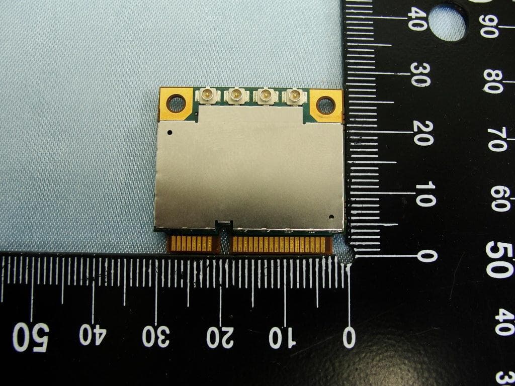
NCMOMO6792
Feb 24, 2013GTM679W
Equipment Class
JBP - Part 15 Class B Computing Device PeripheralNCMOGI0644
Jun 17, 2012GSM/UMTS/WLAN USB Modem GI0644
Equipment Class
PCB - PCS Licensed Transmitter