NCMOGTM353-WGSM/GPRS/UMTS/HSDPA QUAD BAND PCI MINI CARD
Option (Crescent NV)
Click to zoom
Application Details
- Equipment Class
- PCB - PCS Licensed Transmitter
- Date of Grant
- Oct 15, 2006
- Application Purpose
- Original Equipment
- Date of Application
- Oct 12, 2006
- Equipment Note
- GSM/GPRS/UMTS/HSDPA QUAD BAND PCI MINI CARD
- Frequency Range
- 1852.40000000 - 1907.60000000
- Company
- Option (Crescent NV)
- Country
- Belgium
Documents & Files
Document Text
Text extracted from the exhibit documents filed with the FCC. Open a document above to read the original.
Users Manual
OPTION W ireless Technology, Kolonel Begaultlaan 45, B-3012 Leuven Tel +32 16 317 411 Fax +32 16 207 164 http://www.option.com Option Confidential Globetrotter Module GTM353W Integration Manual OPTION W ireless Technology, Kolonel Begaultlaan 45, B-3012 Leuven Tel +32 16 317 411 Fax +32 16 207 164 http://www.option.com Option Confidential About this document Overview and Purpose This document is meant for laptop manufacturers and other system integrators, to allow for easy integration into their own product. The bulk of this document describes the functional interfaces of the GlobeTrotter GTM353W Module on hardware, firmware and software levels. At the end, a chapter concerning certification requirements is added, which should be taken into account from the start of the integration. Please note that this is only a draft version and is subject to change. Confidentiality All data and information contained or disclosed by this document is confidential and proprietary of Option NV, and all rights therein are expressly reserved. By accepting this document, the recipient agrees that this information is held in confidence and in trust and will not be used, copied, reproduced in whole or in part, nor its contents revealed in any manner to others without prior and written permission of Option NV Version History Date Release Version Author(s) Revision(s) Remarks Phase June 8, 2005 1 1-Draft R. Claessens S. Lodeweyckx Added general overview diagram, certification content, quickstart guide, general modifications 1.0.0 June 9, 2005 1 2-Draft R. Claessens Added revision remarks 1.0.0 June 16, 2005 1 3-Draft R. Claessens Added revision remarks 1.0.0 June 22, 2005 1 4-Final R. Claessens S. Lodeweyckx, F. Nys, J. Vercruysse Added antenna guidelines, product pictures 1.0.0 July 8, 2005 2 1-Draft R. Claessens 1.0.0 September 14, 2005 2 4-Final R. Claessens D. Michiels Added default settings for Option AT commands 1.0.0 November 18, 2005 3 1-Final Johan De Bisschop Pinout definition adapted to newly approved PCIExpress Mini Card standard. References to GTM352U removed January 16, 2005 4 1-Draft Johan De Bisschop Update for GTM353W January 18, 2005 4 2-Draft Johan De Bisschop Digital PCM interface added GTM353W Integration Manual Author: R. Claessens Version: 4.0 Draft 2 Creation Date: September 20, 2006 Page: 3 of 52 Option Confidential: This document is Option Confidential - it may not be duplicated, neither distributed externally without prior and written permission of Option NV. Table of contents 1 INTRODUCTION ................................................................................................. 5 1.1 General description ........................................................................................ 5 1.2 Features .......................................................................................................... 6 1.2.1 WCDMA................................................................................................ 6 1.2.2 E-GPRS.................................................................................................. 6 1.2.3 Terminal Equipment Interfaces.............................................................. 7 1.2.4 Power Requirements .............................................................................. 7 1.2.5 Thermal Dissipation and derating .......................................................... 7 1.2.6 LED definition ....................................................................................... 7 2 GENERAL OVERVIEW DIAGRAM .................................................................. 8 3 HARDWARE DESCRIPTION ............................................................................. 9 3.1 Block diagram GTM353W ............................................................................ 9 3.2 PCIExpress Mini Card interface .................................................................... 9 3.3 UICC interface guidelines.............................................................................. 9 3.3.1 Introduction............................................................................................ 9 3.3.2 UICC Interface....................................................................................... 9 3.3.3 Electrical specifications of the UICC – Terminal interface ................... 9 3.3.4 Electrical interface ................................................................................. 9 3.3.5 Practical implementation ....................................................................... 9 3.4 Digital PCM interface .................................................................................... 9 3.4.1 Background ............................................................................................ 9 3.4.2 Interfaces, Features & Functions ........................................................... 9 3.5 Antenna guidelines......................................................................................... 9 3.5.1 Antenna specifications ........................................................................... 9 3.5.2 WLAN Antenna Isolation ...................................................................... 9 3.5.3 Antenna connector ................................................................................. 9 4 HOST CONTROL INTERFACES ........................................................................ 9 4.1 USB interface................................................................................................. 9 4.2 COM interface ............................................................................................... 9 4.3 NDIS interface ............................................................................................... 9 5 DEVICE DRIVER INTERFACE .......................................................................... 9 6 AT COMMAND SET REFERENCE .................................................................... 9 6.1 DTE-TA/DCE Interface Com…
Text truncated - open the document above for the full version.
Users Manual
OPTION NV, Kolonel Begaultlaan 45, B-3012 Leuven Tel +32 16 317 411 Fax +32 16 207 164 http://www.option.com Option Confidential General Document User Manual Cobra Module General Document, Register Cobra module on CMU200 Author: Version: V01 –F1 Creation Date: Jul 31, 2006 Page: 1 of 6 Option Confidential: This document is Option Confidential - it may not be duplicated, neither distributed externally without prior and written permission of Option NV. About this document Overview and Purpose This document describes how to register an Option Cobra Module on a CMU200. Confidentiality All data and information contained or disclosed by this document is confidential and proprietary of Option NV, and all rights therein are expressly reserved. By accepting this document, the recipient agrees that this information is held in confidence and in trust and will not be used, copied, reproduced in whole or in part, nor its contents revealed in any manner to others without prior and written permission of Option NV. Version History Date Version Author(s) Revision(s) Remarks Apr 26, 2006 V01 – F1 R. Biesemans Initial version July 31, 2006 J. Boeckx Review General Document, Register Cobra module on CMU200 Author: Version: V01 –F1 Creation Date: Jul 31, 2006 Page: 2 of 6 Option Confidential: This document is Option Confidential - it may not be duplicated, neither distributed externally without prior and written permission of Option NV. Table of contents 1 INTRODUCTION ................................................................................................................................ 3 2 Registering the module to the CMU200 ............................................................................................... 3 2.1 Settings on CMU200 ................................................................................................................... 3 2.2 Settings on the module ................................................................................................................ 4 3 References............................................................................................................................................. 6 General Document, Register Cobra module on CMU200 Author: Version: V01 –F1 Creation Date: Jul 31, 2006 Page: 3 of 6 Option Confidential: This document is Option Confidential - it may not be duplicated, neither distributed externally without prior and written permission of Option NV. 1 INTRODUCTION This document describes how to register an Option Cobra Module on a CMU 200. This manual will guide you through the steps so you can do some tests on the CMU 200. 2 REGISTERING THE MODULE TO THE CMU200 Note: When mentioned switch off, AT+CFUN should be set to: AT+CFUN=0 When mentioned switch on, AT+CFUN should be set to: AT+CFUN=1 Use RF2 connection of CMU200 to connect the module. Select GSM or WCDMA on CMU. When the card is properly configured, and the preferred band is selected, the card will register automatically on the system. When the card does not register on the CMU with the default setting of the CMU, please check the settings in the following paragraphs. If the CMU has the integrity check enabled, you can use the card without any security setting changes (AT_OSEC=4). If not, please change the OSEC setting of the card: set OSEC to 3 (AT_OSEC=3) using a terminal program (for ex. HyperTerminal). For life networks, integrity checks are default enabled, so the OSEC setting needs to be set on 4. 2.1 Settings on CMU200 1. RF connector compensation: Look if compensation settings are right: AF/RF. In normal use, meaning when your cables are all very well isolated, you have to compensate both directions for a minimum of +0,5 dB. You can choose higher values when you think the cables are not isolated enough. 2. BS signal too low: When at first try, the card doesn’t seem to register, try to increase the BS signal levels. Normal operation would be around 65 dBm. Try this value and switch the card off and on again. After checking these settings. Switch off and switch on the card again. (at+cfun=0 and at+cfun=1) It is also recommended to safe remove the card. General Document, Register Cobra module on CMU200 Author: Version: V01 –F1 Creation Date: Jul 31, 2006 Page: 4 of 6 Option Confidential: This document is Option Confidential - it may not be duplicated, neither distributed externally without prior and written permission of Option NV. 2.2 Settings on the module When previous steps didn’t do the trick, please check the settings on the card. All steps mentioned next, should be evaluated in this order. After each step, perform a safe removal of the card. 1. At_opbm When not working in a shielded environment, all life networks could interfere with the signal coming from the CMU. When the simulated network is not in the same band as the surrounding life networks, this problem can be avoided by deselecting all other basebands but the one you are working in. This could be done using the at_opbm command: Extract from datasheet: Preferred Band Mode _OPBM Command Possible response(s) _OPBM=<band>,<n> OK _ OPBM =? _OPBM: (list of supported <band>s) _ OPBM? <band>: <n>[<CR><LF><band>: <n>[...]] Description This command is used to disable/enable specific frequency bands. Defined Values <band> “ANY” : any band “EGSM” : EGSM (900MHz) band ”DCS” : DCS (1800MHz) band ”PCS” : PCS (1900MHz) band ”G850” : GSM 850MHz band ”U2100” : WCDMA 2100MHz band ”U1900” : WCDMA 1900MHz band “U1700” “U17IV” “U850” : WCDMA 1900MHz band <n> 0 : disable 1 : enable Eg: if you use GSM1900 (PCS) band, select only this band. All other bands have to be deselected. It is also very important to deselect EVERY UMTS band when trying to connect to a GSM network and vice versa: General Document, Register Cobra module on CMU200 Author: Version: V01 –F1 Creation Date: Jul 31, 2006 Page: 5 of 6 Option Confidential: This document is Option Confidential - it may not be duplicated, neither distributed externall…
Text truncated - open the document above for the full version.
Users Manual
GlobeTrotter PCI Express Mini Card Quick Start Guide Module Certification OPTION NV, Gaston Geenslaan 14, 3001 Leuven - Belgium Tel +32 16 317 411 Fax +32 16 207 164 http://www.option.com Option Confidential OPTION NV, Gaston Geenslaan 14, 3001 Leuven - Belgium Tel +32 16 317 411 Fax +32 16 207 164 http://www.option.com Option Confidential About this document Confidentiality All data and information contained or disclosed by this document is confidential and proprietary of Option NV, and all rights therein are expressly reserved. By accepting this document, the recipient agrees that this information is held in confidence and in trust and will not be used, copied, reproduced in whole or in part, nor its contents revealed in any manner to others without prior and written permission of Option NV. Version History Date Version Author(s) Revision(s) Remarks July 31., 2006 J. Boeckx How to amount module Table of contents 1 Introduction..................................................................................................................................... 2 2 Overview......................................................................................................................................... 3 3 Hardware Installation...................................................................................................................... 3 4 Driver Installation........................................................................................................................... 5 4.1 Installation procedure:........................................................................................................... 5 5 HyperTerminal................................................................................................................................9 1 INTRODUCTION For evaluation purposes the GlobeTrotter PCI Express mini cards modules are housed in a cradle, offering a convenient evaluation and development platform. This document further describes the hardware and software installation and basic usage instructions for Windows XP English edition. 2 OVERVIEW 1. SIM card holder 3. Audio CODEC chip reset button 2. SIM card eject mechanism 4. Small USB connector 1 Figure 1: Pepijn Cradle bottom view 3 HARDWARE INSTALLATION Step-by-step instructions: (1) Insert the module skew into the cradle and (2) push the module down, so it makes proper contact in the PCI Express connector. (3) Secure the module with the locking mechanism. Remark: Fasten the screw of the locking mechanism when it becomes too loose by holding one finger on top of the screw and turning the leg in counter clockwise direction. Figure 2: Module and Cradle board (4) Carefully insert your SIM card in the SIM card holder (with the contact side up), and (5) insert the holder into the socket, making sure it is aligned correctly. To remove the SIM card holder, (6) press the small eject button with the tip of a pen (you may need to apply gentle force). 1 The small and big USB connector both work for the same USB interface OPTION NV, Gaston Geenslaan 14, 3001 Leuven - Belgium Tel +32 16 317 411 Fax +32 16 207 164 http://www.option.com Option Confidential Figure 3: SIM card holder (7) Connect the external antenna (or SMA connector cable for test equipment) to the RF connector on the module. Figure 4: RF connector on the module (8) Connect the headset into the audio jack (MODULE WILL ALSO WORK PROPERLY EVEN WITHOUT THIS JACK). Next, (9) connect the power supply plug (the adapter should already be connected to the mains) to the evaluation platform. And when you are ready you can (10) connect the USB cable from the GTM cradle to your PC. At this point your module should be detected by the host PC. OPTION NV, Gaston Geenslaan 14, 3001 Leuven - Belgium Tel +32 16 317 411 Fax +32 16 207 164 http://www.option.com Option Confidential Figure 5: Top to bottom: USB cable, power plug and audio jack NOTES: In case a hard reset of the unit is necessary, unplug the power supply and wait until the power led (led closest to the fan) is fully extinguished before reconnecting the power supply (A large buffer capacitor on the cradle board needs about 10 seconds to discharge). 4 DRIVER INSTALLATION Following drivers are available for Win XP, Win 2K and Win XP x64 edition: • Device: GlobeTrotter Module 3G+ • Multifunction Adapter: GlobeTrotter Module 3G+ Flip-Flop Bus • Port: GlobeTrotter Module 3G+ Diagnostics Port • Port: GlobeTrotter Module 3G+ Application Port • Network: GlobeTrotter Module 3G+ Network Card • Modem: GlobeTrotter Module 3G+ Modem • Smart Card: GlobeTrotter Module 3G+ Smart Card Interface (Optional) For full functionality of your module, you need to make sure all drivers are installed correctly. 4.1 Installation procedure: (1) If you have not already done so, install and connect the cradle as described in chapter 3. The unit is connected correctly only if the “Found New Hardware” balloon and subsequent “Welcome to the Found New Hardware” Wizard appears. Figure 6: Found New Hardware OPTION NV, Gaston Geenslaan 14, 3001 Leuven - Belgium Tel +32 16 317 411 Fax +32 16 207 164 http://www.option.com Option Confidential Figure 7: Welcome to the Found New Hardware Wizard (2) For Windows XP: on the first dialog (“Can Windows connect to Windows Update to search for software?”) select “No, not this time” (3) On the next dialog, select ”Install software automatically (Recommended)”. At this point make sure the CD-ROM with drivers is inserted into your optical drive. Figure 8: Install the software automatically (Recommended) Or if you know the location of the drivers yourself you can select “Install from a list or specific location (Advanced)”. In this case make sure to select the option “Include this location in the search:” in the next screen and enter the correct path to your drivers. OPTION NV, Gaston Geenslaan 14, 3001 Leuven - Belgium Tel +32 16 317 411 Fax +32 16 207 164 http://www.option.com Option Confidential Figure 9: In…
Text truncated - open the document above for the full version.
Cover Letter(s)
Generic Office of Engineering Technology <[email protected] > 22.09.2006 15:32 An [email protected] Kopie Blindkopie Thema Response to Inquiry to FCC (Tracking Number 701219) Inquiry: Dear FCC, According to the current policy for TCBs on the handling of 3G mobile phone technologies, the TCB has to involve the FCC prior to certifying any 3G device. We are currently in the process of certifying following device: Modular Transmitter - GSM 850 / PCS 1900 / WCDMA 850 + 1900 MHz Recent FCC trainings, telephone conference calls and the Preliminary Guidance for Reviewing Applications for Certifications of 3G Devices (May 9,2005) have been taken into consideration. Please confirm or advice. Response: FCC recommends using the SAR test procedures for 3G devices as described in the attached documents. These procedures must be used for applications submitted to TCBs for approval. Questions about using alternative procedures should be submitted at www .fcc.gov/labhelp. Do not reply to this message. Please select the Reply to an Inquiry Response link from the OET Inquiry System to add any additional information pertaining to this inquiry.
Cover Letter(s)
Option nv sa | Kolonel Begaultlaan 45 | B-3012 Leuven Belgium | www.option.com T +32 16 317 411 | F +32 16 207 164 | H.R.L./R.C.L. 68114 | BTW/TVA BE 429.375.448 Declaration of Product Name Equality We, Option N.V., declare on our sole responsibility that the names Cobra Triple ; Cobra v 3.1 ; Cobra v 3.2 ; GTM353-W are referring to the same product. The difference between the names is due to the use of respectively engineering names Cobra and the official name GTM353W. Cobra Triple is the internal engineering name GTM353-W is the official marketing name Cobra v3.1 is the initial product version Cobra v3.2 refers to the final product version, it’s a hardware update for v3.1. Ref: “Hardware Declaration Cobra Triple v3.1 to v3.2.pdf” Company : Option N.V. Gaston Geenslaan 14 3001 Leuven Belgium Point of contact : Stefan Lodeweyckx Phone : +32 16 317 411 Fax : +32 16 207 164 e-mail : [email protected] Leuven, September 19., 2006
ID Label/Location Info
Kol. Begaultlaan 45 - B3012 Leuven Belgium Rev:SAP Material Nr : Part Name: Page: Size:Scale: Drawn: Top Material Nr: Date: Project: F Tested to Comply With FCC Standards For Home or Office Use FCC ID NCMOGTM353-W QUALCOMM 3G CDMA 2001341_1_2001341 Model: GT M353W Made in Ireland by Option Designed in E.U. by Option 1.Overall dimensions: 26.5mm x 25mm 2.To be supplied in the format shown, on reels, copy position 2, internal core dia 38mm 3.Quantity per roll: 1000 or max o/d 4” 4.Each roll to be packed in bubble wrap and sealed in a polythene bag containing no other shedding material. Reels then to be packed in a box, each box to contain 4 reels. The outside of the box to be clearly labeled with the following information: - Option Part number - Quantity in box - Date produced 5.Liner to be 6.Label thickness: 50 TBDmm wide. Vertical gap between labels TBDmm. μm max. 7.Label to be silver and suitable for thermal transfer printing. 8.Label to be printed with artwork_art.* 9.Printing be resistant to rubbing and alcohol cleaning. 10. Raw material: FLEXcon THERMLfilm MM 200 satin silver TC-715 L-344 40 White Glassine 11. Artwork use black 32364 12. To be used with print ribbon: Armor AXR7+ or equivalent. 2001341_1_2001341 2001341 1 DATE APPROVED ISSUEDDESCRIPTION REV ECP 1 First draft / Derived from CO1LBL-21861TS 4111 03/07/06 1/1 A4 1:1 Manufacturing Label Cobra 3U Thomas STEVENS COBRA 3U 03/07/06 ArtworkOutline 25.0 20.0 16.0 26.5 5.3 2001341
Operational Description
GTM3 51W GTM353W The GTM353W PCIExpress MiniCard module is providing Wireless WAN func- tionalities to any device with a PCIExpress Minicard slot. In particular, the GTM353W is the solution of choice for embedding 3G and Edge connectivity technology into laptop and PDA devices. It supports HSDPA 1.8 Mbps, UMTS WCDMA in the three 850/1900/2100MHz bands and GPRS/EDGE in four bands (850/900/1800/1900 MHz), thereby ensuring worldwide UMTS/HSDPA and E-GPRS operations HSDPA | UMTS | E-GPRS pciexpress minicard module with triple band umts features > Supports triple band UMTS and quad-band E-GPRS/GSM , enabling worldwide roaming on 2G and 3G networks > Multimode UMTS/E-GPRS/GPRS/GSM card with HSDPA 1.8 Mbps support > Provides HSDPA High-speed data (up to 1.8 Mbps downlink and up to 384kbps uplink) connectivity on HSDPA-equipped networks > Provides UMTS High-speed data (up to 384 kbps) connectivity on UMTS networks > Provides E-GPRS/GPRS/GSM data (up to 247 kbps) connectivity > Low power dissipation for easy embedding into devices > Transparent handover between UMTS and GSM/E-GPRS networks > Benefits from large Option experience in data PC-cards > Tested on infrastructures and networks worldwide > Flexible driver design providing both NDIS and modem modes for easy integration into dashboard applications > Future proofing through Flash Memory technology > Connector for external antenna > Connector for external SIM/UICC holder Z06.087_GTM 353W_DS_V2.indd 128-06-2006 10:25:44 Kolonel Begaultlaan 45 | 3012 Leuven Belgium | T +32 16 317 411 | F +32 16 207 164 | www.option.com GTM353W specifications > HSDPA/UMTS . WCDMA 850/1900/2100 MHz . 3GPP FDD compliant, up to 1.8Mbps Peak Rate . UE Power Class 3 (+24 dBm) . High Speed packet-switched data: › Support for UMTS QoS traffic classes › Support for PPP, IP transparent and non-transparent modes . Circuit-switched data Single-RAB streaming: 64, 57.6, 28.8 and 14.4 kbps > E-GPRS . 850/900/1800/1900 MHz . GSM Power Class 4 (2W) for 850/900 bands, GSM . Power Class 1 (1W) for 1800/1900 bands . EDGE class E2 (+27 dBm in 850/900 bands, +26 dBm in 1800/1900 bands) . GPRS/EGPRS Multislot Class 10 (4 slots Rx, 2 slots Tx, 5 max active) . GPRS/EGPRS Class B Type 1 MT . GPRS CS1-CS4; EGPRS MCS1-MCS9 . Circuit Switched Data: 14.4 and 9.6 kbps thermal dissipation > 2500 mW at 70°C @ 3.3V > 2750 mW at 70°C @ 3.3V+8% terminal equipment interfaces > USB 1.1 signaling > AT interface with standard modem emulation > NDIS and Modem interface drivers . NDIS required for OS compliance and future proofing (Longhorn) . Modem interface required to allow 3rd party application support > EAP-SIM / EAP-AKA support > Operating Systems supported: . Windows 2000/XP Home/ XP Pro/ Vista . Tablet/XP Pro/Mac OS X Tiger > PCM voice support on PCIE minicard interface (final pin assignment still TBD) regulatory & certifications > R&TTE, GCF for WCDMA > R&TTE, GCF, FCC, PTCRB for EGPRS power Requirements > Vcc 3.3V +/- 8% > Peak Icc 2750 mA with max supply drop 50 mV > Average Icc 1000 mA As part of their continual product improvement process Option reserve the right to alter the specifications for the product detailed here. HSDPA | UMTS | E-GPRS Picture of embedded wireless module with cover shielding removed.Picture of embedded wireless module with cover shielding removed. Z06.087_GTM 353W_DS_V2.indd 228-06-2006 10:26:13
RF Exposure Info
4_OPTI_0306_ERF RF exposure requirements – FCC ID: NCMOGTM353-W Dear Examiner, GTM353W is marketed without defined antenna. According to the limit in 47 CFR 1.1310, we get the value of the maximum antenna gain as follow: The maximum measured power output in the 850 MHz band is 1513.56 mW (31.8dBm, see 7layers test report 4_OPTI_0306_ERF_FCCa), The maximum permissible exposure is defined in 47 CFR 1.1310 with 0,56 mW/cm². The transmitter is using indoor antennas that operate at 20 cm or more from nearby persons. The maximum antenna gain G is calculated using the general equation: S = P*G/4πR² S = 0,56 mW/cm² P = 1513.56 mW R = 20 cm π = 3.1416 Solving for G; the maximum antenna gain is 2.7 dBi. Please contact us if you have any additional questions. Best Regards 7 layers AG i.A. Thomas Hoell 7 layers AG Aufsichtsratsvorsitzenderh Registergerichth registered in: Borsigstrasse 11 Chairman of the Supervisory Board: Düsseldorf, HRB 44096 40880 Ratingen, Germany Markus Becker USt-IdNr h VAT Nr: Phone: +49 (0) 2102 749 0 Vorstandh Board: DE 203159652 Fax: +49 (0) 2102 749 350 Dr. Hans-Jürgen Meckelburg www.7Layers.com René Schildknecht
RF Exposure Info
4_OPTI_0306_ERF RF exposure requirements – FCC ID: NCMOGTM353-W Dear Examiner, GTM353W is marketed without defined antenna. According to the limit in 47 CFR 1.1310, we get the value of the maximum antenna gain as follow: The maximum measured power output in the 850 MHz band is 691.8 mW (31.8dBm, see 7layers test report 4_OPTI_0306_ERF_FCCb), The maximum permissible exposure is defined in 47 CFR 1.1310 with 1 mW/cm². The transmitter is using indoor antennas that operate at 20 cm or more from nearby persons. The maximum antenna gain G is calculated using the general equation: S = P*G/4πR² S = 1 mW/cm² P = 691.8 mW R = 20 cm π = 3.1416 Solving for G; the maximum antenna gain is 8.6 dBi. Please contact us if you have any additional questions. Best Regards 7 layers AG i.A. Thomas Hoell 7 layers AG Aufsichtsratsvorsitzenderh Registergerichth registered in: Borsigstrasse 11 Chairman of the Supervisory Board: Düsseldorf, HRB 44096 40880 Ratingen, Germany Markus Becker USt-IdNr h VAT Nr: Phone: +49 (0) 2102 749 0 Vorstandh Board: DE 203159652 Fax: +49 (0) 2102 749 350 Dr. Hans-Jürgen Meckelburg www.7Layers.com René Schildknecht
Test Report
7 layers AGAufsichtsratsvorsitzenderhRegistergerichthregistered in: Borsigstrasse 11Chairman of the Supervisory Board:Düsseldorf, HRB 44096 40880 Ratingen, GermanyMarkus BeckerUSt-IdNr hVAT Nr: Phone: +49 (0) 2102 749 0Vorstand h Board:DE 203159652 Fax: +49 (0) 2102 749 350Dr. Hans-Jürgen Meckelburg www.7Layers.comRené Schildknecht InterLab ® is a registered trademark of 7 layers AG FCC Measurement/Technical Report on GSM Module GTM353W Report Reference:4_Opti_0306_ERF_FCCa Test Laboratory: 7 layers AG Borsigstrasse 11 40880 Ratingen Germany email: [email protected] DAT-P-192/99-01 Note: The following test results relate only to the devices specified in this document. This report shall not be reproduced in parts without the written approval of the testing laboratory. Test report Reference: 4_Opti_0306_ERF_FCCaPage 2 of 69 Table of Contents 0 Summary3 0.1Technical Report Summary3 0.2Measurement Summary4 1 Administrative Data6 1.1Testing Laboratory6 1.2Project Data6 1.3Applicant Data6 1.4Manufacturer Data6 2 Testobject Data7 2.1General EUT Description7 2.2EUT Main components8 2.3Ancillary Equipment8 2.4EUT Setups8 2.5Operating Modes9 3 Test Results10 3.1RF Power Output10 3.2Frequency stability14 3.3Spurious emissions at antenna terminals19 3.4Field strength of spurious radiation24 3.5Emission and Occupied Bandwidth28 3.6Band edge compliance32 4 Test Equipment35 5 Photo Report38 6 Setup Drawings44 7 Annex46 Measurement Plots Test report Reference: 4_Opti_0306_ERF_FCCaPage 3 of 69 0 Summary 0.1 Technical Report Summary Type of Authorization Certification for a GSM cellular radiotelephone device Applicable FCC Rules Prepared in accordance with the requirements of FCC Rules and Regulations as listed in 47 CFR Ch.1 Parts 0 to 19 and Parts 20 to 69 (10-1-05 Edition). The following subparts are applicable to the results in this test report. Part 2 Subpart J - Equipment Authorization Procedures, Certification § 2.1046 Measurement required: RF power output § 2.1049 Measurement required: Occupied bandwidth § 2.1051 Measurement required: Spurious emissions at antenna terminals § 2.1053 Measurement required: Field strength of spurious radiation § 2.1055 Measurement required: Frequency stability § 2.1057 Frequency spectrum to be investigated Part 22 Subpart C – Operational and Technical Requirements § 22.355 Frequency tolerance Subpart H – Cellular Radiotelephone Service § 22.913 Effective radiated power limits § 22.917 Emission limitations for cellular equipment Summary Test The EUT complied with all performed tests as listed in chapter 0.2 Measurement Summary. Test report Reference: 4_Opti_0306_ERF_FCCaPage 4 of 69 0.2 Measurement Summary RF Power Output The measurement was performed according to FCC §2.1046 10-1-05 OP-ModeSe…
Text truncated - open the document above for the full version.
Contact Information
Applicant
Joost van der Velden(CEO)
Test Firm
7layers AGRobert Machulec
Technical Specifications
| # | Rule Parts | Frequency Range | Power Output | Emission | Tolerance |
|---|---|---|---|---|---|
| 6 | 24E | 1.85 GHz - 1.91 GHz | 258.00 mW | 4M20F9W | 0.1 ppm |
Other Applications from Option (Crescent NV)

NCM-CG2132
Sep 21, 2022LoRaWAN 86x/9xx Expansion card
Equipment Class
DTS - Digital Transmission System
NCM-WT500
Jun 06, 2021Water and Temperature Sensor
Equipment Class
DSS - Part 15 Spread Spectrum Transmitter
NCMOCG2101
Feb 27, 2013CloudGate 802.11abgn Wireless LAN Card
Equipment Class
NII - Unlicensed National Information Infrastructure TX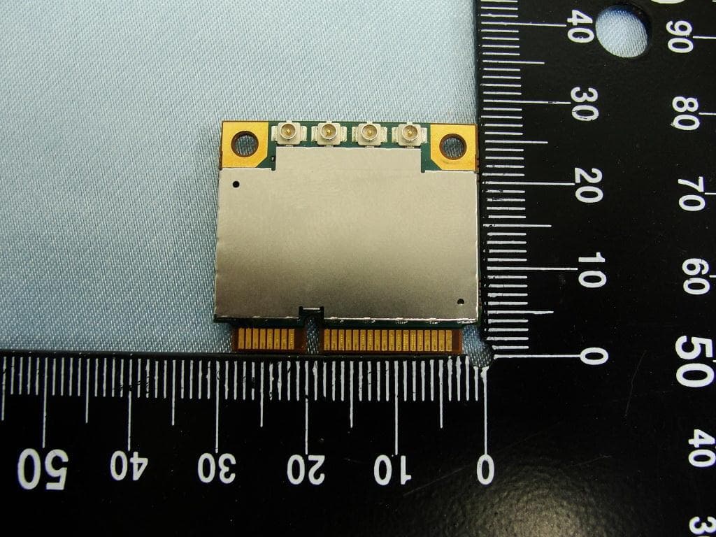
NCMOMO6792
Feb 24, 2013GTM679W
Equipment Class
JBP - Part 15 Class B Computing Device PeripheralNCMOGI0644
Jun 17, 2012GSM/UMTS/WLAN USB Modem GI0644
Equipment Class
PCB - PCS Licensed Transmitter