NCMOMO0205GSM/GPRS/UMTS/HSDPA/EDGE PCI MINI CARD MODULE
Option (Crescent NV)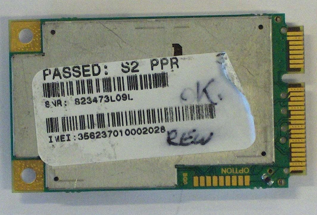
Click to zoom
Application Details
- Equipment Class
- PCB - PCS Licensed Transmitter
- Date of Grant
- May 15, 2007
- Application Purpose
- Original Equipment
- Date of Application
- May 15, 2007
- Equipment Note
- GSM/GPRS/UMTS/HSDPA/EDGE PCI MINI CARD MODULE
- Frequency Range
- 1850.20000000 - 1909.80000000
- Company
- Option (Crescent NV)
- Country
- Belgium
Documents & Files
Document Text
Text extracted from the exhibit documents filed with the FCC. Open a document above to read the original.
Users Manual
GlobeTrotter GTM378EL AGENCY REQUIREMENTS Licensed by QUALCOMM Incorporated under one or more of the following United States Patents and/or their counterparts in other nations: 4,901,307; 5,490,165; 5,056,109; 5,504,773; 5,101,501; 5,506,865; 5,109,390; 5,511,073; 5,228,054; 5,535,239; 5,267,261; 5,544,196; 5,267,262; 5,568,483; 5,337,338; 5,600,754; 5,414,796; 5,657,420; 5,416,797; 5,659,569; 5,710,784; 5,778,338 Federal communications commission notice This equipment has been tested and found to comply with the limits for a Class B digital device, pursuant to Part 15 of the FCC Rules. These limits are designed to provide reasonable protection against harmful interference in a residential installation. This equipment generates, uses, and can radiate radio frequency energy and, if not installed and used in accordance with the instructions, may cause harmful interference to radio communications. However, there is no guarantee that interference will not occur in a particular installation. If this equipment does cause harmful interference to radio or television reception, which can be determined by turning the equipment off and on, the user is encouraged to try to correct the interference by one or more of the following measures: > Reorient or relocate the receiving antenna. > Increase the separation between the equipment and receiver. > Connect the equipment into an outlet on a circuit different from that to which the receiver is connected. > Consult the dealer or an experienced radio or television technician for help. FCC RF Exposure Requirement This device complies with FCC RF Exposure Requirements set forth for an uncontrolled/general population environment. A separation distance of 20 cm between the transmitting antenna and the human body must be assured during normal operating conditions. Modifications The FCC requires the user to be notified that any changes or modifications made to this device that are not expressly approved by Option could void the user's authority to operate the equipment. Cables The use of shielded cables for connection of the monitor to the graphics card is required to assure compliance with FCC regulations. (Part 15.105 only applies for digital devices in the meaning of the FCC rules) Declaration of Conformity for products marked with the FCC logo - United States only This device complies with Part 15 of the FCC rules. Operation is subject to the following two conditions: (1) this device may not cause harmful interference, and (2) this device must accept any interference received, including interference that may cause undesired operation. For questions regarding your product or FCC declaration, contact: Option | Gaston Geenslaan 14| 3001 Leuven | Belgium www.option.com To identify this product, refer to the Part, Series, or Model number found on the product. This product has successfully completed the PTCRB requirements governing the release of new GSM 850/1900 capable products into the North American market. European Union declaration of conformity CE 0700 Products bearing the CE marking comply with the R&TTE Directive (99/5/EC), EMC Directive (89/336/EEC) and the Low Voltage Directive (73/23/EEC) issued by the Commission of the European Community. Compliance with these directives implies conformity to the following European Norms (in parentheses are the equivalent international standards and regulations): Radio Frequency spectrum efficiency: > EN 301 511, v9.0.2 > EN 301 902-1&2, v2.2.1 Electromagnetic Compatibility > EN 301 489-1,-7,-24: 2002 Safety and Health > EN 60950: 2001 This product may be used in the following countries: > All EU Memberstates > Iceland > Switzerland > Norway > United States of America Manufacturer's Disclaimer Statement The information in this document is subject to change without notice and does not represent a commitment on the part of the vendor. No warranty or representation, either expressed or implied, is made with respect to the quality, accuracy, or fitness for any particular purpose of this document. The manufacturer reserves the right to make changes to the content of this document and/or the products associated with it at any time without obligation to notify any person or organization of such changes. In no event will the manufacturer be liable for direct, indirect, special, incidental, or consequential damages arising out of the use or inability to use this product or documentation, even if advised of the possibility of such damages. For questions regarding your product or declaration, contact: Option | Gaston Geenslaan 14| 3001 Leuven | Belgium www.option.com SYSTEM REQUIREMENTS > This is a module and should be integrated in devices mentioned in the “Integration manual”
Cover Letter(s)
Request for Confidentiality PHOENIX TESTLAB GmbH Date: 16.May 2007 Product Certification Koruqswinkel 10 D 32825 Blomberg RE: Certification Application FCC ID: NCMOM00205 Confidentiality Request Pursuant to Sections 0.457 and 0.459 of the Commission's Rule, the applicant hereby requests confidential treatment of information accompanying th is application as outlined below: • Schematics • Parts List I Tune up info • Block D iagram • Users Manual (highly technical I non-consumer device) • Operational Description The above materials contain trade secrets and proprietary information not customarily released to the public. The public disclosure of these matters might be harmful to the applicant and provide unjustified benefits to its competitors. Also, in accordance with FCC Public DA 04-1705, we request short-term confidentiality for exhibits, which contain External and Internal Photos. These exhibits contain pre-market information, which could give competitors unfair advantage should this infor mation be released before this product is actually introduced into the common marketplace. The applicant understands that pursuant to rule 0.457, disclosure of this application and all accompanying documentation will not be made before the date of the GRANT for this application . Thank you for your attention in this matter. 7 layers AG Borsigstr. 11 40880 Ratingen, Germany Signature Job Title and Dept. : Yao Jing, Project manager
ID Label/Location Info
Rev:SAP Material Nr : Part Name: Page: Size:Scale: Drawn: Top Material Nr: Date: Project: Gaston Geenslaan 14 - B3001 Leuven - Belgium 1.Overall dimensions: 26.5mm x 25mm 2.To be supplied in the format shown, on reels, copy position 2, internal core dia 40 mm 3.Quantity per roll: 5000 or max o/d 4” 4.Each roll to be packed in bubble wrap and sealed in a polythene bag containing no other shedding material. Reels then to be packed in a box, each box to contain 4 reels. The outside of the box to be clearly labeled with the following information: - Option Part number - Quantity in box - Date produced 5.Liner to be 32 6.Label thickness: 50 mm wide. Vertical gap between labels 32 mm. μm max. 7.Label to be silver and suitable for thermal transfer printing. 8.Label to be printed with artwork 9.Printing be resistant to rubbing and alcohol cleaning. 10.Raw material: Brady B-435 11. Artwork use Black 12.To be used with print ribbon: Brady R-6006 200xxxx_1_200xxxx_art.* 200xxxx 1 Outline Thermal print (suggestion) 200xxxx SCORPION Manf LBL SCORPION Lite Eric Vandeputte 12/03/07 1:1 A4 1/1 DATE APPROVED ISSUEDDESCRIPTION REV ECP 1 Scorpion Lite MO0205 EV 18/04/07 27.0 5.5 16.0 2 1 , 2 2 6 . 4 Artwork 2 0 0 x x x x QUALCOMM 3G WCDMA Made in China Designed in E.U. by Option 2 0 0 x x x x QUALCOMM 3G WCDMA Made in China Designed in E.U. by Option FCC ID NCMOMO0205 IMEI : xxxxxxxxxxxxx SNR : xxxxxxxxxx Model: MO0205
Test Report
7 layers AG Aufsichtsratsvorsitzenderh Registergerichth registered in: Borsigstrasse 11 Chairman of the Supervisory Board: Düsseldorf, HRB 44096 40880 Ratingen, Germany Markus Becker USt-IdNr h VAT Nr: Phone: +49 (0) 2102 749 0 Vorstandh Board: DE 203159652 Fax: +49 (0) 2102 749 350 Dr. Hans-Jürgen Meckelburg www.7Layers.com René Schildknecht InterLab ® is a registered trademark of 7 layers AG FCC Measurement/Technical Report on GSM/UMTS Module MO0205 based on GSM/UMTS Module MO0201 Report Reference: MDE_Opti_0705_FCCa Test Laboratory: 7 layers AG Borsigstrasse 11 40880 Ratingen Germany email: [email protected] DAT-P-192/99-01 Note: The following test results relate only to the devices specified in this document. This report shall not be reproduced in parts without the written approval of the testing laboratory. Test report Reference: MDE_Opti_0705_FCCa Page 2 of 60 Table of Contents 0 Summary 3 0.1 Technical Report Summary 3 0.2 Measurement Summary 4 1 Administrative Data 6 1.1 Testing Laboratory 6 1.2 Project Data 6 1.3 Applicant Data 6 1.4 Manufacturer Data 6 2 Testobject Data 7 2.1 General EUT Description 7 2.2 EUT Main components 8 2.3 Ancillary Equipment 8 2.4 EUT Setups 8 2.5 Operating Modes 9 3 Test Results 10 3.1 RF Power Output 10 3.2 Frequency stability 13 3.3 Spurious emissions at antenna terminals 17 3.4 Field strength of spurious radiation 21 3.5 Emission and Occupied Bandwidth 25 3.6 Band edge compliance 29 4 Test Equipment 31 5 Photo Report 34 6 Setup Drawings 43 7 Annex 45 Measurement Plots Test report Reference: MDE_Opti_0705_FCCa Page 3 of 60 0 Summary 0.1 Technical Report Summary Type of Authorization Certification for a GSM cellular radiotelephone device Applicable FCC Rules Prepared in accordance with the requirements of FCC Rules and Regulations as listed in 47 CFR Ch.1 Parts 0 to 19 and Parts 20 to 69 (10-1-06 Edition). The following subparts are applicable to the results in this test report. Part 2 Subpart J - Equipment Authorization Procedures, Certification § 2.1046 Measurement required: RF power output § 2.1049 Measurement required: Occupied bandwidth § 2.1051 Measurement required: Spurious emissions at antenna terminals § 2.1053 Measurement required: Field strength of spurious radiation § 2.1055 Measurement required: Frequency stability § 2.1057 Frequency spectrum to be investigated Part 22 Subpart C – Operational and Technical Requirements § 22.355 Frequency tolerance Subpart H – Cellular Radiotelephone Service § 22.913 Effective radiated power limits § 22.917 Emission limitations for cellular equipment Summary Test The EUT complied with all performed tests as listed in chapter 0.2 Measurement Summary. Test report Reference: MDE_Opti_0705_FCCa Page 4 of 60 0.2 Measurement Summary RF Power Output The measurement was performed according to FCC §2.1046 10-1-06 OP-Mode Setup Port Final Result op-mode 1 setup_b01 antenna connector passed op-mode 2 setup_b01 antenna connector passed op-mode 3 setup_b01 antenna connector passed op-mode 4 setup_b01 antenna connector passed op-mode 5 setup_b01 antenna connector passed op-mode 6 setup_b01 antenna connector passed Frequency stability The measurement was performed according to FCC §2.1055 10-1-06 OP-Mode Setup Port Final Result op-mode 2 setup_01 antenna connector passed op-mode 5 setup_01 antenna connector passed Spurious emissions at antenna terminals The measurement was performed according to FCC §2.1051 10-1-06 OP-Mode Setup Port Final Result op-mode 1 setup_a01 antenna connector passed op-mode 2 setup_01 antenna connector passed op-mode 3 setup_a01 antenna connector passed op-mode 4 setup_a01 antenna connector passed op-mode 5 setup_01 antenna connector passed op-mode 6 setup_a01 antenna connector passed Field strength of spurious radiation The measurement was performed according to FCC §2.1053 10-1-06 OP-Mode Setup Port Final Result op-mode 1 setup_b02 enclosure passed op-mode 2 setup_b02 enclosure passed op-mode 3 setup_b02 enclosure passed op-mode 4 setup_b02 enclosure passed op-mode 5 setup_b02 enclosure passed op-mode 6 setup_b02 enclosure passed "ayers Emission and Occupied Bandwidth The measurement was performed according to FCC §2.1049 OP-Mode Setup Port op-mode 1 setup_01 antenna connector op-mode 2 setup_01 antenna connector op-mode 3 setup_01 antenna connector op-mode 4 setup_01 antenna connector o p- m o d e 5 setup_01 anten na connector op-mode 6 setup_01 antenna connector 10-1-06 Final Result passed passed passed pas sed passed passed Band edge compliance The measurement was performed according to FCC §2.1053 10-1-06 OP-Mode Setup Port Final Result op -mode 1 setup_01 antenna co n n ect o r pas sed op -mode 3 setup_01 anten na connector passed op -mode 4 setup_01 antenna connector passed op-mode 6 setup_01 antenna connector passed The module M00205 is based on the module M00201 but the UMTS bands FDD II and FDD V are not supported by M00205. The tests "RF Power Output" and "Field strength of spurious radiation" were retested with MO 0205. ~ I Y rs 7 lay ers AG. Bo rsigslr. 11 40 80 P t,,1ge n, Germany . Phc n ...49 (0 )2102 749 0 Respo nsible (\ \/ J / # Accredit a tio n Scope: _______ ____ for Test Report: ~ tJ.e.u- Resporsible for Pag e 5 of 60 Test report Reference: MDE_Opti_0705_FCCa Page 6 of 60 1 Administrative Data 1.1 Testing Laboratory Company Name: 7 Layers AG Address Borsigstr. 11 40880 Ratingen Germany This facility has been fully described in a report submitted to the FCC and accepted under the registration number 96716 . The test facility is also accredited by the following accreditation organisation: - Deutscher Akkreditierungs Rat DAR-Registration no. DAT-P-192/99-01 Responsible for Accreditation Scope: Dipl.-Ing. Bernhard Retka Dipl.-Ing. Robert Machulec Dipl.-Ing. Thomas Hoell Report Template Version: 2006-12-18 1.2 Project Data Responsible for testing and report: Dipl.-Ing. Thomas Hoell Receipt of EUT: please refer to chapter 2.2 Date of Test(s): 2006-12-19 to 2007-01-30; 2007-04-02 t…
Text truncated - open the document above for the full version.
Test Report
7 layers AG Aufsichtsratsvorsitzenderh Registergerichth registered in: Borsigstrasse 11 Chairman of the Supervisory Board: Düsseldorf, HRB 44096 40880 Ratingen, Germany Markus Becker USt-IdNr h VAT Nr: Phone: +49 (0) 2102 749 0 Vorstandh Board: DE 203159652 Fax: +49 (0) 2102 749 350 Dr. Hans-Jürgen Meckelburg www.7Layers.com René Schildknecht InterLab ® is a registered trademark of 7 layers AG FCC Measurement/Technical Report on GSM/UMTS Module MO0205 based on GSM/UMTS Module MO0201 Report Reference: MDE_Opti_0705_FCCb Test Laboratory: 7 layers AG Borsigstrasse 11 40880 Ratingen Germany email: [email protected] DAT-P-192/99-01 Note: The following test results relate only to the devices specified in this document. This report shall not be reproduced in parts without the written approval of the testing laboratory. Test report Reference: MDE_Opti_0705_FCCb Page 2 of 60 Table of Contents 0 Summary 3 0.1 Technical Report Summary 3 0.2 Measurement Summary 4 1 Administrative Data 6 1.1 Testing Laboratory 6 1.2 Project Data 6 1.3 Applicant Data 6 1.4 Manufacturer Data 6 2 Testobject Data 7 2.1 General EUT Description 7 2.2 EUT Main components 8 2.3 Ancillary Equipment 8 2.4 EUT Setups 8 2.5 Operating Modes 9 3 Test Results 10 3.1 RF Power Output 10 3.2 Frequency stability 13 3.3 Spurious emissions at antenna terminals 17 3.4 Field strength of spurious radiation 21 3.5 Emission and Occupied Bandwidth 25 3.6 Band edge compliance 29 4 Test Equipment 31 5 Photo Report 34 6 Setup Drawings 43 7 Annex 45 Measurement Plots Test report Reference: MDE_Opti_0705_FCCb Page 3 of 60 0 Summary 0.1 Technical Report Summary Type of Authorization Certification for a GSM cellular radiotelephone device Applicable FCC Rules Prepared in accordance with the requirements of FCC Rules and Regulations as listed in 47 CFR Ch.1 Parts 0 to 19 and Parts 20 to 69 (10-1-06 Edition). The following subparts are applicable to the results in this test report. Part 2 Subpart J - Equipment Authorization Procedures, Certification § 2.1046 Measurement required: RF power output § 2.1049 Measurement required: Occupied bandwidth § 2.1051 Measurement required: Spurious emissions at antenna terminals § 2.1053 Measurement required: Field strength of spurious radiation § 2.1055 Measurement required: Frequency stability § 2.1057 Frequency spectrum to be investigated Part 24 Subpart E - Broadband PCS § 24.232 Power and antenna height limits § 24.235 Frequency stability § 24.236 Field strength limits § 24.238 Emission limitations for Broadband PCS equipment Summary Test Results: The EUT complied with all performed tests as listed in chapter 0.2 Measurement Summary. Test report Reference: MDE_Opti_0705_FCCb Page 4 of 60 0.2 Measurement Summary RF Power Output The measurement was performed according to FCC §2.1046 10-1-06 OP-Mode Setup Port Final Result op-mode 1 setup_b01 antenna connector passed op-mode 2 setup_b01 antenna connector passed op-mode 3 setup_b01 antenna connector passed op-mode 4 setup_b01 antenna connector passed op-mode 5 setup_b01 antenna connector passed op-mode 6 setup_b01 antenna connector passed Frequency stability The measurement was performed according to FCC §2.1055 10-1-06 OP-Mode Setup Port Final Result op-mode 2 setup_01 antenna connector passed op-mode 5 setup_01 antenna connector passed Spurious emissions at antenna terminals The measurement was performed according to FCC §2.1051 10-1-06 OP-Mode Setup Port Final Result op-mode 1 setup_a01 antenna connector passed op-mode 2 setup_01 antenna connector passed op-mode 3 setup_a01 antenna connector passed op-mode 4 setup_a01 antenna connector passed op-mode 5 setup_01 antenna connector passed op-mode 6 setup_a01 antenna connector passed Field strength of spurious radiation The measurement was performed according to FCC §2.1053 10-1-06 OP-Mode Setup Port Final Result op-mode 1 setup_b02 enclosure passed op-mode 2 setup_b02 enclosure passed op-mode 3 setup_b02 enclosure passed op-mode 4 setup_b02 enclosure passed op-mode 5 setup_b02 enclosure passed op-mode 6 setup_b02 enclosure passed layers Emission and Occupied Bandwidth The measurement was performed according to FCC §2.1049 OP-Mode Setup Port op-mode 1 setup_01 antenna connector op-mode 2 setup_01 antenna connector op-mode 3 setup_01 antenna connector op-mode 4 setup_01 antenna connector op-mode 5 setup_01 antenna connector op-rnode 6 setup_01 antenna connector 10-1-06 Final Result passed passed passed passed passed passed Band edge compliance The measurement was performed according to FCC §24.238 10-1-06 OP-Mode Setup Port Final Result op-mode 1 setup_01 antenna connector passed op-mode 3 setup_01 antenna connector passed op-mode 4 setup_01 antenna connector passed op-mode 6 setup_01 antenna connector passed The m o d u le M00205 is based on the module M00201 but the UMTS bands FDD II and FDD V are not supported by M00205. The tests "RF Power Output" and "Field strength of spurious radiation" were retested with MO 0205. 7 layers AG so rs: str . 1 4 0 88 0 Rau ;J n, Germany . Phone +49 \ 0) 210 2 7490 Responsible for Responsible Accreditation Scope: for Test Report: Page 5o f 60 Test report Reference: MDE_Opti_0705_FCCb Page 6 of 60 1 Administrative Data 1.1 Testing Laboratory Company Name: 7 Layers AG Address Borsigstr. 11 40880 Ratingen Germany This facility has been fully described in a report submitted to the FCC and accepted under the registration number 96716 . The test facility is also accredited by the following accreditation organisation: - Deutscher Akkreditierungs Rat DAR-Registration no. DAT-P-192/99-01 Responsible for Accreditation Scope: Dipl.-Ing. Bernhard Retka Dipl.-Ing. Robert Machulec Dipl.-Ing. Thomas Hoell Report Template Version: 2006-12-18 1.2 Project Data Responsible for testing and report: Dipl.-Ing. Thomas Hoell Receipt of EUT: please refer to chapter 2.2 Date of Test(s): 2006-12-19 to 2007-01-30; 2007-04-03 to 2007-04-04 Date of Report: 2007-04-12 1.3 Applicant Data Company Name: Option NV Addr…
Text truncated - open the document above for the full version.
Test Setup Photos
Test report Reference: MDE_Opti_0705_FCCa Page 34 of 60 5 Photo Report Photo 1: EUT A (front side) Test report Reference: MDE_Opti_0705_FCCa Page 35 of 60 Photo 2: EUT B (front side) Test report Reference: MDE_Opti_0705_FCCa Page 36 of 60 Photo 3: EUT C (front side) Test report Reference: MDE_Opti_0705_FCCa Page 37 of 60 Photo 4: EUT A (rear side) Test report Reference: MDE_Opti_0705_FCCa Page 38 of 60 Photo 5: EUT B (rear side) Test report Reference: MDE_Opti_0705_FCCa Page 39 of 60 Photo 6: EUT C (rear side) Test report Reference: MDE_Opti_0705_FCCa Page 40 of 60 Photo 7: Setup for radiated tests (EUT C operated in a cradle and with external antenna) Test report Reference: MDE_Opti_0705_FCCa Page 41 of 60 Photo 8: Cradle AE1 (front side) Test report Reference: MDE_Opti_0705_FCCa Page 42 of 60 Photo 9: Cradle AE1 (rear side)
Contact Information
Applicant
Joost van der Velden(CEO)
Technical Contact
Non-Technical Contact
Option N.VStefan Lodeweyckx
[email protected]+32 16 317-411
Test Firm
7layers AGRobert Machulec
Technical Specifications
| # | Rule Parts | Frequency Range | Power Output | Emission | Tolerance |
|---|---|---|---|---|---|
| 4 | 24E | 1.85 GHz - 1.91 GHz | 457.00 mW | 300KG7W | 2.5 ppm |
Other Applications from Option (Crescent NV)

NCM-CG2132
Sep 21, 2022LoRaWAN 86x/9xx Expansion card
Equipment Class
DTS - Digital Transmission System
NCM-WT500
Jun 06, 2021Water and Temperature Sensor
Equipment Class
DSS - Part 15 Spread Spectrum Transmitter
NCMOCG2101
Feb 27, 2013CloudGate 802.11abgn Wireless LAN Card
Equipment Class
NII - Unlicensed National Information Infrastructure TX
NCMOMO6792
Feb 24, 2013GTM679W
Equipment Class
JBP - Part 15 Class B Computing Device PeripheralNCMOGI0644
Jun 17, 2012GSM/UMTS/WLAN USB Modem GI0644
Equipment Class
PCB - PCS Licensed Transmitter