NCMOMO0301EGSM/GPRS/UMTS/HSDPA QUAD BAND PCI MINI EXPRESS CAR
Option (Crescent NV)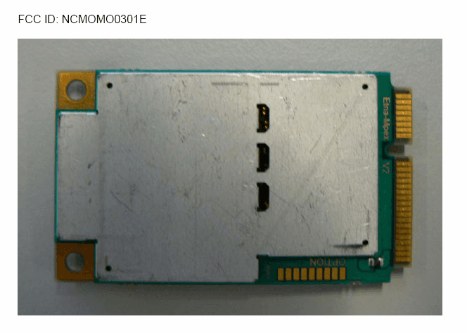
Click to zoom
Application Details
- Equipment Class
- PCB - PCS Licensed Transmitter
- Date of Grant
- Sep 03, 2007
- Application Purpose
- Original Equipment
- Date of Application
- Sep 03, 2007
- Equipment Note
- GSM/GPRS/UMTS/HSDPA QUAD BAND PCI MINI EXPRESS CAR
- Frequency Range
- 1852.40000000 - 1907.60000000
- Company
- Option (Crescent NV)
- Country
- Belgium
Documents & Files
Document Text
Text extracted from the exhibit documents filed with the FCC. Open a document above to read the original.
Users Manual
GlobeTrotter Connect User Guide Connect anytime, anywhere 2 TABLE OF CONTENTS 1. SYSTEM REQUIREMENTS 3 2. PRODUCT FEATURES 3 3. SHORT DESCRIPTION AND INTENDED USE 3 3.1. Basic Use 3 4. INSTALLING AND SETTING UP GLOBETROTTER CONNECT 4 4.1. Installation 4 4.2. Installation process 6 4.3. Running GlobeTrotter Connect 7 4.4. Entering your PIN code 7 4.5. Checking Status 7 4.6. Exit GlobeTrotter Connect 8 5. SETTING UP A CONNECTION TO THE INTERNET 9 5.1. Connecting to the Internet 9 5.2. Disconnecting 10 5.3. Changing the program options 10 5.3.1. APN 11 5.3.2. Enable / Disable the Pin Code 11 5.3.3. Technology Selection 11 6. PRODUCT SUPPORT AND ADDITIONAL HELP 12 7. PRODUCT SUPPORT AND ADDITIONAL HELP 14 7.1. Technical Support 14 APPENDIX A: LIMITED WARRANTY 15 3 GlobeTrotter Connect USER GUIDE 1. SYSTEM REQUIREMENTS Windows ® 2000, XP, Vista 5Mb free hard disk space 2. PRODUCT FEATURES • Easy installation • Simple intuitive user interface • Compatible with most modern desktop and laptop PC’s equipped with Microsoft Windows ® 2000, XP, Vista 3. SHORT DESCRIPTION AND INTENDED USE The GlobeTrotter Connect application is a small, easy to use tool to manage your connection to the Internet over 2G and 3G mobile networks. It is designed for use with all of Option’s data products. 3.1. Basic Use The focus is on simplicity and most users will use it only in basic mode, where it displays a window with network information and a Connect button. The main purpose is therefore simply to Connect/Disconnect to and from the Internet. • Figure 1: GlobeTrotter Connect For Basic View NOTE: Some versions of GT Connect contain an SMS module. In this case the Close button says ‘SMS Centre’. 4 4. INSTALLING AND SETTING UP GLOBETROTTER CONNECT 4.1. Installation GlobeTrotter Connect can be installed in several ways: 1. You can install it from a CD if provided. Browse on the CD-ROM and look for setup.exe. Double click it to start the installation. The following screen appears. • Figure 2: GlobeTrotter Connect Installation Wizard Click “Next” to continue the installation and use the Browse button to specify the folder where you want to have the software installed. • Figure 3: Specify installation folder 5 GlobeTrotter Connect USER GUIDE The GlobeTrotter Connect application is now ready for installation. Click “Next” and the actual installation will start. • Figure 4: GlobeTrotter Connect ready to Install After GlobeTrotter Connect is installed, the following screen will be shown. Click “Finish” to close the installation wizard. • Figure 5: Successfully installed GlobeTrotter Connect 2. Download it free from http://www.option.com/support/login.shtml and run the installation file. Follow the same procedure as described in 1. 3. If your Option data product is equipped with Zero-CD TM technology the application is installed as soon as you connect the product for the first time. For a short time the ZeroCD icon will be visible in Explorer. • Figure 6: ZeroCD drive 6 4.2. Installation process The installation process is straightforward. You will see the following screen appear. • Figure 7: GlobeTrotter Connect Installation Screen Wait until the process is completed. You will see the following screen to indicate that the software has been installed. • Figure 8: GlobeTrotter Connect Installation Completed In the mean time, you will see various balloons appear indicating the installation process of your Option device. Wait until the following balloon to indicate that the process has finished. • Figure 9: Found New Hardware Balloon 7 GlobeTrotter Connect USER GUIDE 4.3. Running GlobeTrotter Connect As soon as you plug in a compatible communications device (Card, USB device...). GlobeTrotter Connect shows up in the Systray. • Figure 10: GlobeTrotter Connect icon GlobeTrotter Connect is now ready to make a connection. Don’t forget that apart from the software the Option communications device also needs to be ready. E.g. you can’t use the device while it isn’t registered to the network or if the PIN code hasn’t been entered yet. 4.4. Entering your PIN code If you have enabled the PIN code on your SIM card you will automatically be asked to type it in. If enabled you won’t be able to use your data device until you have typed in the PIN code. This will happen every time you power up the device. • Figure 11: Pin Code Dialog 4.5. Checking Status Once the PIN code is entered (or immediately if you have disabled the PIN code) the device will look for the network. You can check the status by moving your mouse pointer over the GlobeTrotter Connect icon to get a quick status report showing the network name, technology being used and the signal quality: 8 • Figure 12: Network Information Balloon If GlobeTrotter Connect is opened, you can see the signal strength immediately in the lower right corner. If you need to know the signal strength more accurately (e.g. in fringe areas you may want to determine the location where you have the best reception) double-click on the signal strength indicator to see an enlarged view of the signal strength indicator. • Figure 13: Signal Strength Indicator The indicator next to the signal strenght shows 3G if you have a 3G coverage. Once you have a connection the indicator shows HS if an HSDPA (HS) connection was established. • Figure 14: Enlarged Signal Strength Indicator 4.6. Exit GlobeTrotter Connect When you click or this doesn’t kill the application. It just retreats to the Systray (see Figure 10: GlobeTrotter Connect icon). This behaviour is equivalent to other Windows applications such as MSN messenger. To terminate the application you must ‘Right Click’ on the Title Bar and choose Exit. 9 GlobeTrotter Connect USER GUIDE • Figure 15: Exit GlobeTrotter Connect 5. SETTING UP A CONNECTION TO THE INTERNET When you want to connect to the Internet you need to specify how you want to connect. You can do this in the settings screen (see the “Changing the program options” section of this manual). As your mobil…
Text truncated - open the document above for the full version.
Users Manual
MO0301 AGENCY REQUIREMENTS Licensed by QUALCOMM Incorporated under one or more of the following United States Patents and/or their counterparts in other nations: 4,901,307; 5,490,165; 5,056,109; 5,504,773; 5,101,501; 5,506,865; 5,109,390; 5,511,073; 5,228,054; 5,535,239; 5,267,261; 5,544,196; 5,267,262; 5,568,483; 5,337,338; 5,600,754; 5,414,796; 5,657,420; 5,416,797; 5,659,569; 5,710,784; 5,778,338 Federal communications commission notice This equipment has been tested and found to comply with the limits for a Class B digital device, pursuant to Part 15 of the FCC Rules. These limits are designed to provide reasonable protection against harmful interference in a residential installation. This equipment generates, uses, and can radiate radio frequency energy and, if not installed and used in accordance with the instructions, may cause harmful interference to radio communications. However, there is no guarantee that interference will not occur in a particular installation. If this equipment does cause harmful interference to radio or television reception, which can be determined by turning the equipment off and on, the user is encouraged to try to correct the interference by one or more of the following measures: > Reorient or relocate the receiving antenna. > Increase the separation between the equipment and receiver. > Connect the equipment into an outlet on a circuit different from that to which the receiver is connected. > Consult the dealer or an experienced radio or television technician for help. Modifications The FCC requires the user to be notified that any changes or modifications made to this device that are not expressly approved by Option could void the user's authority to operate the equipment. Cables The use of shielded cables for connection of the monitor to the graphics card is required to assure compliance with FCC regulations. (Part 15.105 only applies for digital devices in the meaning of the FCC rules) Declaration of Conformity for products marked with the FCC logo - United States only This device complies with Part 15 of the FCC rules. Operation is subject to the following two conditions: (1) this device may not cause harmful interference, and (2) this device must accept any interference received, including interference that may cause undesired operation. For questions regarding your product or FCC declaration, contact: Option | Gaston Geenslaan 14| 3001 Leuven | Belgium www.option.com To identify this product, refer to the Part, Series, or Model number found on the product. European Union declaration of conformity CE 0700 Products bearing the CE marking comply with the R&TTE Directive (99/5/EC), EMC Directive (89/336/EEC) and the Low Voltage Directive (73/23/EEC) issued by the Commission of the European Community. Compliance with these directives implies conformity to the following European Norms (in parentheses are the equivalent international standards and regulations): Radio Frequency spectrum efficiency: > EN 301 511, v9.0.2 > EN 301 902-1&2, v2.2.1 Electromagnetic Compatibility > EN 301 489-1,-7,-24: 2002 Safety and Health > EN 60950: 2001 This product may be used in the following countries: > All EU Memberstates > Iceland > Switzerland > Norway > United States of America Manufacturer's Disclaimer Statement The information in this document is subject to change without notice and does not represent a commitment on the part of the vendor. No warranty or representation, either expressed or implied, is made with respect to the quality, accuracy, or fitness for any particular purpose of this document. The manufacturer reserves the right to make changes to the content of this document and/or the products associated with it at any time without obligation to notify any person or organization of such changes. In no event will the manufacturer be liable for direct, indirect, special, incidental, or consequential damages arising out of the use or inability to use this product or documentation, even if advised of the possibility of such damages. For questions regarding your product or declaration, contact: Option | Gaston Geenslaan 14| 3001 Leuven | Belgium www.option.com SYSTEM REQUIREMENTS > This is a module and should be integrated in devices mentioned in the “Integration manual”
Users Manual
MO0301 AGENCY REQUIREMENTS Licensed by QUALCOMM Incorporated under one or more of the following United States Patents and/or their counterparts in other nations: 4,901,307; 5,490,165; 5,056,109; 5,504,773; 5,101,501; 5,506,865; 5,109,390; 5,511,073; 5,228,054; 5,535,239; 5,267,261; 5,544,196; 5,267,262; 5,568,483; 5,337,338; 5,600,754; 5,414,796; 5,657,420; 5,416,797; 5,659,569; 5,710,784; 5,778,338 Federal communications commission notice This equipment has been tested and found to comply with the limits for a Class B digital device, pursuant to Part 15 of the FCC Rules. These limits are designed to provide reasonable protection against harmful interference in a residential installation. This equipment generates, uses, and can radiate radio frequency energy and, if not installed and used in accordance with the instructions, may cause harmful interference to radio communications. However, there is no guarantee that interference will not occur in a particular installation. If this equipment does cause harmful interference to radio or television reception, which can be determined by turning the equipment off and on, the user is encouraged to try to correct the interference by one or more of the following measures: > Reorient or relocate the receiving antenna. > Increase the separation between the equipment and receiver. > Connect the equipment into an outlet on a circuit different from that to which the receiver is connected. > Consult the dealer or an experienced radio or television technician for help. Modifications The FCC requires the user to be notified that any changes or modifications made to this device that are not expressly approved by Option could void the user's authority to operate the equipment. Cables The use of shielded cables for connection of the monitor to the graphics card is required to assure compliance with FCC regulations. (Part 15.105 only applies for digital devices in the meaning of the FCC rules) Declaration of Conformity for products marked with the FCC logo - United States only This device complies with Part 15 of the FCC rules. Operation is subject to the following two conditions: (1) this device may not cause harmful interference, and (2) this device must accept any interference received, including interference that may cause undesired operation. For questions regarding your product or FCC declaration, contact: Option | Gaston Geenslaan 14| 3001 Leuven | Belgium www.option.com To identify this product, refer to the Part, Series, or Model number found on the product. European Union declaration of conformity CE 0700 Products bearing the CE marking comply with the R&TTE Directive (99/5/EC), EMC Directive (89/336/EEC) and the Low Voltage Directive (73/23/EEC) issued by the Commission of the European Community. Compliance with these directives implies conformity to the following European Norms (in parentheses are the equivalent international standards and regulations): Radio Frequency spectrum efficiency: > EN 301 511, v9.0.2 > EN 301 902-1&2, v2.2.1 Electromagnetic Compatibility > EN 301 489-1,-7,-24: 2002 Safety and Health > EN 60950: 2001 This product may be used in the following countries: > All EU Memberstates > Iceland > Switzerland > Norway > United States of America Manufacturer's Disclaimer Statement The information in this document is subject to change without notice and does not represent a commitment on the part of the vendor. No warranty or representation, either expressed or implied, is made with respect to the quality, accuracy, or fitness for any particular purpose of this document. The manufacturer reserves the right to make changes to the content of this document and/or the products associated with it at any time without obligation to notify any person or organization of such changes. In no event will the manufacturer be liable for direct, indirect, special, incidental, or consequential damages arising out of the use or inability to use this product or documentation, even if advised of the possibility of such damages. For questions regarding your product or declaration, contact: Option | Gaston Geenslaan 14| 3001 Leuven | Belgium www.option.com SYSTEM REQUIREMENTS > This is a module and should be integrated in devices mentioned in the “Integration manual”
RF Exposure Info
,'ayers RF exposure requirements -FCC ID: NCMOM00301E Dear Examiner, MO 0301 is marketed without defined antenna. According to the limit in 47 CFR 1.1310, we get the value of the maximum antenna gain as follow: The maximum measured power output in the 850 MHz band is 1548.82 mW (31.9dBm, see 71ayers test report MDE_OPTI_0709_FCCa). The maximum permissible exposure is defined in 47 CFR 1.1310 with 0.55773 mW/cm 2 • The transmitter is using indoor antennas that operate at 20 cm or more from nearby persons. The maximum antenna gain G is calculated using the general equation: S = P*G/411:R 2 S = 0.55'773 mW/cm 2 P = 1548.82 mW R = 20 cm 11: = 3.14'16 Solving for G; the maximum antenna gain is 2.5770 dBi. Best Regards 7 layers AG ,',;( J ~ i.A. Hoiger Leutfeld .'ayers RF exposure requirements -FCC ID: NCMOM00301E Dear Examiner, M00205 is marketed without defined antenna. According to the limit in 47 CFR 1.1310, we get the value of the maximum antenna gain as follow: The maximum measured power output in the 1900 MHz band is 724.44 mW (28.6 dBrn, see 71ayers test report MDE_OPTI_0709_FCCb). The maximum permissible exposure is defined in 47 CFR 1.1310 with 1 mW/cm 2 • The transmitter is using indoor antennas that operate at 20 cm or more from nearby persons. The maximum antenna gain G is calculated using the general equation: S = P*G/47tR 2 S = 1 mVV/cm 2 P = 724.44 mW R=20 cm 7t=3.1416 Solving for G; the maximum antenna gain is 8.4127 dBL Best Re~lards 7 layers AG A-A. £/ LA. Holger Leutfeld
RF Exposure Info
,'ayers RF exposure requirements -FCC ID: NCMOM00301E Dear Examiner, MO 0301 is marketed without defined antenna. According to the limit in 47 CFR 1.1310, we get the value of the maximum antenna gain as follow: The maximum measured power output in the 850 MHz band is 1548.82 mW (31.9dBm, see 71ayers test report MDE_OPTI_0709_FCCa). The maximum permissible exposure is defined in 47 CFR 1.1310 with 0.55773 mW/cm 2 • The transmitter is using indoor antennas that operate at 20 cm or more from nearby persons. The maximum antenna gain G is calculated using the general equation: S = P*G/411:R 2 S = 0.55'773 mW/cm 2 P = 1548.82 mW R = 20 cm 11: = 3.14'16 Solving for G; the maximum antenna gain is 2.5770 dBi. Best Regards 7 layers AG ,',;( J ~ i.A. Hoiger Leutfeld .'ayers RF exposure requirements -FCC ID: NCMOM00301E Dear Examiner, M00205 is marketed without defined antenna. According to the limit in 47 CFR 1.1310, we get the value of the maximum antenna gain as follow: The maximum measured power output in the 1900 MHz band is 724.44 mW (28.6 dBrn, see 71ayers test report MDE_OPTI_0709_FCCb). The maximum permissible exposure is defined in 47 CFR 1.1310 with 1 mW/cm 2 • The transmitter is using indoor antennas that operate at 20 cm or more from nearby persons. The maximum antenna gain G is calculated using the general equation: S = P*G/47tR 2 S = 1 mVV/cm 2 P = 724.44 mW R=20 cm 7t=3.1416 Solving for G; the maximum antenna gain is 8.4127 dBL Best Re~lards 7 layers AG A-A. £/ LA. Holger Leutfeld
Test Report
7 layers AG Aufsichtsratsvorsitzenderh Registergerichth registered in: Borsigstrasse 11 Chairman of the Supervisory Board: Düsseldorf, HRB 44096 40880 Ratingen, Germany Markus Becker USt-IdNr h VAT Nr: Phone: +49 (0) 2102 749 0 Vorstandh Board: DE 203159652 Fax: +49 (0) 2102 749 350 Dr. Hans-Jürgen Meckelburg www.7Layers.com René Schildknecht InterLab ® is a registered trademark of 7 layers AG FCC Measurement/Technical Report on GSM/UMTS Module MO0301 Report Reference: MDE_Opti_0709_FCCd Test Laboratory: 7 layers AG Borsigstrasse 11 40880 Ratingen Germany email: [email protected] DAT-P-192/99-01 Note: The following test results relate only to the devices specified in this document. This report shall not be reproduced in parts without the written approval of the testing laboratory. Test report Reference: MDE_Opti_0709_FCCd Page 2 of 63 Table of Contents 0 Summary 3 0.1 Technical Report Summary 3 0.2 Measurement Summary 4 1 Administrative Data 6 1.1 Testing Laboratory 6 1.2 Project Data 6 1.3 Applicant Data 6 1.4 Manufacturer Data 6 2 Testobject Data 7 2.1 General EUT Description 7 2.2 EUT Main components 8 2.3 Ancillary Equipment 8 2.4 EUT Setups 8 2.5 Operating Modes 9 3 Test Results 10 3.1 RF Power Output 10 3.2 Frequency stability 13 3.3 Spurious emissions at antenna terminals 18 3.4 Field strength of spurious radiation 22 3.5 Emission and Occupied Bandwidth 26 3.6 Band edge compliance 29 4 Test Equipment 32 5 Photo Report 35 6 Setup Drawings 38 7 Annex 40 Measurement Plots Test report Reference: MDE_Opti_0709_FCCd Page 3 of 63 0 Summary 0.1 Technical Report Summary Type of Authorization Certification for a GSM cellular radiotelephone device Applicable FCC Rules Prepared in accordance with the requirements of FCC Rules and Regulations as listed in 47 CFR Ch.1 Parts 0 to 19 and Parts 20 to 69 (10-1-06 Edition). The following subparts are applicable to the results in this test report. Part 2 Subpart J - Equipment Authorization Procedures, Certification § 2.1046 Measurement required: RF power output § 2.1049 Measurement required: Occupied bandwidth § 2.1051 Measurement required: Spurious emissions at antenna terminals § 2.1053 Measurement required: Field strength of spurious radiation § 2.1055 Measurement required: Frequency stability § 2.1057 Frequency spectrum to be investigated Part 22 Subpart C – Operational and Technical Requirements § 22.355 Frequency tolerance Subpart H – Cellular Radiotelephone Service § 22.913 Effective radiated power limits § 22.917 Emission limitations for cellular equipment Summary Test The EUT complied with all performed tests as listed in chapter 0.2 Measurement Summary. Test report Reference: MDE_Opti_0709_FCCd Page 4 of 63 0.2 Measurement Summary RF Power Output The measurement was performed according to FCC §2.1046 10-1-06 OP-Mode Setup Port Final Result op-mode 1 Setup_a02 antenna connector passed op-mode 2 Setup_a02 antenna connector passed op-mode 3 Setup_a02 antenna connector passed op-mode 4 Setup_a02 antenna connector passed op-mode 5 Setup_a02 antenna connector passed op-mode 6 Setup_a02 antenna connector passed op-mode 7 Setup_a02 antenna connector passed op-mode 8 Setup_a02 antenna connector passed op-mode 9 Setup_a02 antenna connector passed Frequency stability The measurement was performed according to FCC §2.1055 10-1-06 OP-Mode Setup Port Final Result op-mode 2 Setup_a02 antenna connector passed op-mode 5 Setup_a02 antenna connector passed op-mode 8 Setup_a02 antenna connector passed Spurious emissions at antenna terminals The measurement was performed according to FCC §2.1051 10-1-06 OP-Mode Setup Port Final Result op-mode 1 Setup_a02 antenna connector passed op-mode 2 Setup_a02 antenna connector passed op-mode 3 Setup_a01 antenna connector passed op-mode 4 Setup_a02 antenna connector passed op-mode 5 Setup_a02 antenna connector passed op-mode 6 Setup_a02 antenna connector passed op-mode 7 Setup_a02 antenna connector passed op-mode 8 Setup_a02 antenna connector passed op-mode 9 Setup_a02 antenna connector passed Field strength of spurious radiation The measurement was performed according to FCC §2.1053 10-1-06 OP-Mode Setup Port Final Result op-mode 1 Setup_a03 Enclosure passed op-mode 2 Setup_a03 Enclosure passed op-mode 3 Setup_a03 Enclosure passed op-mode 4 Setup_a03 Enclosure passed op-mode 5 Setup_a03 Enclosure passed op-mode 6 Setup_a03 Enclosure passed op-mode 7 Setup_a03 Enclosure passed op-mode 8 Setup_a03 Enclosure passed op-mode 9 Setup_a03 Enclosure passed _~layers Emission and Occupied Bandwidth The measurement was performed according to FCC §2.1049 OP-Mode Setup Port op-mode 1 Setup_a02 antenna connector op-mode 2 Setup_a02 antenna connector op-mode 3 Setup_a02 antenna connector op-mode 4 Setup_a02 antenna connector op-mode 5 Setup_a02 antenna connector op-mode 6 Setup_a02 antenna connector op-mode 7 Setup_a02 antenna connector op-mode 8 Setup_a02 antenna connector op-mode 9 Setup_a02 antenna connector 10-1-06 Final Result passed passed passed passed passed passed passed passed passed Band edge compliance The measurement was performed according to FCC §2.1053 10-1-06 OP-Mode Setup Port Final Result op-mode 1 Setup_a02 antenna connector passed op-mode 3 Setup_a02 antenna connector passed op-mode 4 Setup_a02 antenna connector passed op-mode 6 Setup_a02 antenna connector passed op-mode 7 Setup_a02 antenna connector passed op-mode 9 Setup_a02 antenna connector passed This test report replaces the 7 layers test report reference MDE_Opti_0709a, dated 2007-08-03. 7 layer AG, Bar '95 r • 1 40880 Rat ngt=n, G", -3 , Phone 1"49 (U)2 OL 14~ Responsible for rr ...;J~ Responsible n /"I) J Accreditation Scope: ~>J-rr--=------for Test Report: -U. ~ Page 5of63 Test report Reference: MDE_Opti_0709_FCCd Page 6 of 63 1 Administrative Data 1.1 Testing Laboratory Company Name: 7 Layers AG Address Borsigstr. 11 40880 Ratingen Germany This facility has been fully described in a report submitted to the FCC and accepted under the registration number 9671…
Text truncated - open the document above for the full version.
Test Report
7 layers AG Aufsichtsratsvorsitzenderh Registergerichth registered in: Borsigstrasse 11 Chairman of the Supervisory Board: Düsseldorf, HRB 44096 40880 Ratingen, Germany Markus Becker USt-IdNr h VAT Nr: Phone: +49 (0) 2102 749 0 Vorstandh Board: DE 203159652 Fax: +49 (0) 2102 749 350 Dr. Hans-Jürgen Meckelburg www.7Layers.com René Schildknecht InterLab ® is a registered trademark of 7 layers AG FCC Measurement/Technical Report on GSM/UMTS Module MO0301 Report Reference: MDE_Opti_0709_FCCe Test Laboratory: 7 layers AG Borsigstrasse 11 40880 Ratingen Germany email: [email protected] DAT-P-192/99-01 Note: The following test results relate only to the devices specified in this document. This report shall not be reproduced in parts without the written approval of the testing laboratory. Test report Reference: MDE_Opti_0709_FCCe Page 2 of 63 Table of Contents 0 Summary 3 0.1 Technical Report Summary 3 0.2 Measurement Summary 4 1 Administrative Data 6 1.1 Testing Laboratory 6 1.2 Project Data 6 1.3 Applicant Data 6 1.4 Manufacturer Data 6 2 Testobject Data 7 2.1 General EUT Description 7 2.2 EUT Main components 8 2.3 Ancillary Equipment 8 2.4 EUT Setups 8 2.5 Operating Modes 9 3 Test Results 10 3.1 RF Power Output 10 3.2 Frequency stability 13 3.3 Spurious emissions at antenna terminals 18 3.4 Field strength of spurious radiation 22 3.5 Emission and Occupied Bandwidth 26 3.6 Band edge compliance 29 4 Test Equipment 32 5 Photo Report 35 6 Setup Drawings 38 7 Annex 40 Measurement Plots Test report Reference: MDE_Opti_0709_FCCe Page 3 of 63 0 Summary 0.1 Technical Report Summary Type of Authorization Certification for a GSM cellular radiotelephone device Applicable FCC Rules Prepared in accordance with the requirements of FCC Rules and Regulations as listed in 47 CFR Ch.1 Parts 0 to 19 and Parts 20 to 69 (10-1-06 Edition). The following subparts are applicable to the results in this test report. Part 2 Subpart J - Equipment Authorization Procedures, Certification § 2.1046 Measurement required: RF power output § 2.1049 Measurement required: Occupied bandwidth § 2.1051 Measurement required: Spurious emissions at antenna terminals § 2.1053 Measurement required: Field strength of spurious radiation § 2.1055 Measurement required: Frequency stability § 2.1057 Frequency spectrum to be investigated Part 24 Subpart E - Broadband PCS § 24.232 Power and antenna height limits § 24.235 Frequency stability § 24.236 Field strength limits § 24.238 Emission limitations for Broadband PCS equipment Summary Test Results: The EUT complied with all performed tests as listed in chapter 0.2 Measurement Summary. Test report Reference: MDE_Opti_0709_FCCe Page 4 of 63 0.2 Measurement Summary RF Power Output The measurement was performed according to FCC §2.1046 10-1-06 OP-Mode Setup Port Final Result op-mode 1 Setup_a02 antenna connector passed op-mode 2 Setup_a02 antenna connector passed op-mode 3 Setup_a02 antenna connector passed op-mode 4 Setup_a02 antenna connector passed op-mode 5 Setup_a02 antenna connector passed op-mode 6 Setup_a02 antenna connector passed op-mode 7 Setup_a02 antenna connector passed op-mode 8 Setup_a02 antenna connector passed op-mode 9 Setup_a02 antenna connector passed Frequency stability The measurement was performed according to FCC §2.1055 10-1-06 OP-Mode Setup Port Final Result op-mode 2 Setup_a02 antenna connector passed op-mode 4 Setup_a02 antenna connector passed op-mode 8 Setup_a02 antenna connector passed Spurious emissions at antenna terminals The measurement was performed according to FCC §2.1051 10-1-06 OP-Mode Setup Port Final Result op-mode 1 Setup_a01 antenna connector passed op-mode 2 Setup_a01 antenna connector passed op-mode 3 Setup_a01 antenna connector passed op-mode 4 Setup_a01 antenna connector passed op-mode 5 Setup_a01 antenna connector passed op-mode 6 Setup_a01 antenna connector passed op-mode 7 Setup_a01 antenna connector passed op-mode 8 Setup_a01 antenna connector passed op-mode 9 Setup_a01 antenna connector passed Field strength of spurious radiation The measurement was performed according to FCC §2.1053 10-1-06 OP-Mode Setup Port Final Result op-mode 1 Setup_a03 Enclosure passed op-mode 2 Setup_a03 Enclosure passed op-mode 3 Setup_a03 Enclosure passed op-mode 4 Setup_a03 Enclosure passed op-mode 5 Setup_a03 Enclosure passed op-mode 6 Setup_a03 Enclosure passed op-mode 7 Setup_a03 Enclosure passed op-mode 8 Setup_a03 Enclosure passed op-mode 9 Setup_a03 Enclosure passed • layers Emission and Occupied Bandwidth The measurement was performed according to FCC §2.1D49 OP-Mode Setup Port op-mode 1 Setup_aD1 antenna connector op-mode 2 Setup_aOl antenna connector op-mode 3 Setup_aD1 antenna connector op-mode 4 Setup_aD1 antenna connector op-mode 5 Setup_a01 antenna connector op-mode 6 Setup_aD! antenna connector op-mode 7 Setup_a01 antenna connector op-mode 8 Setup_aDI antenna connector op-mode 9 Setup_aD1 antenna connector ID-I-D6 Final Result passed passed passed passed passed passed passed passed passed Band edge compliance The measurement was performed according to FCC §24.238 10-1-D6 OP-Mode Setup Port Final Result op-mode 1 Setup_aD! antenna connector passed op-mode 3 Setup_aD! antenna connector passed op-mode 4 Setup_aD1 antenna connector passed op-mode 6 Setup_aD! antenna connector passed op-mode 7 Setup_a01 antenna connector passed op-mode 9 Setup_aD1 antenna connector passed This test report replaces the 7 layers test report reference MDE_OptL0709b, dated 2007-D8-03. 7 layers AG, Borsrgstr. 11 40880 Ra Ingen, Germ ny Phone i-49 (0)2102 ';.1 U ResponSible for Accreditation Scope: A" ~ A I ~ Responsible for Test Report: n -L.{. (J) L~ Page 5of63 Test report Reference: MDE_Opti_0709_FCCe Page 6 of 63 1 Administrative Data 1.1 Testing Laboratory Company Name: 7 Layers AG Address Borsigstr. 11 40880 Ratingen Germany This facility has been fully described in a report submitted to the FCC and accepted under the registration number 96716 . The test facility is also accredi…
Text truncated - open the document above for the full version.
Test Report
7 layers AG Aufsichtsratsvorsitzenderh Registergerichth registered in: Borsigstrasse 11 Chairman of the Supervisory Board: Düsseldorf, HRB 44096 40880 Ratingen, Germany Markus Becker USt-IdNr h VAT Nr: Phone: +49 (0) 2102 749 0 Vorstandh Board: DE 203159652 Fax: +49 (0) 2102 749 350 Dr. Hans-Jürgen Meckelburg www.7Layers.com René Schildknecht InterLab ® is a registered trademark of 7 layers AG FCC Measurement/Technical Repor…
Text truncated - open the document above for the full version.
Contact Information
Applicant
Joost van der Velden(CEO)
Test Firm
7layers AGRobert Machulec
Technical Specifications
| # | Rule Parts | Frequency Range | Power Output | Emission | Tolerance |
|---|---|---|---|---|---|
| 6 | 24E | 1.85 GHz - 1.91 GHz | 321.00 mW | 4M20F9W | 2.5 ppm |
Other Applications from Option (Crescent NV)

NCM-CG2132
Sep 21, 2022LoRaWAN 86x/9xx Expansion card
Equipment Class
DTS - Digital Transmission System
NCM-WT500
Jun 06, 2021Water and Temperature Sensor
Equipment Class
DSS - Part 15 Spread Spectrum Transmitter
NCMOCG2101
Feb 27, 2013CloudGate 802.11abgn Wireless LAN Card
Equipment Class
NII - Unlicensed National Information Infrastructure TX
NCMOMO6792
Feb 24, 2013GTM679W
Equipment Class
JBP - Part 15 Class B Computing Device PeripheralNCMOGI0644
Jun 17, 2012GSM/UMTS/WLAN USB Modem GI0644
Equipment Class
PCB - PCS Licensed Transmitter