NEEE01USB Read / Write Module
Hitachi Maxell Ltd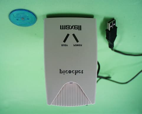
Click to zoom
Application Details
- Equipment Class
- DXX - Part 15 Low Power Communication Device Transmitter
- Date of Grant
- Jan 22, 2001
- Application Purpose
- Original Equipment
- Date of Application
- Jan 22, 2001
- Equipment Note
- USB Read / Write Module
- Frequency Range
- 13.56000000 - 13.56000000
- Company
- Hitachi Maxell Ltd
- Country
- Japan
Documents & Files
Document Text
Text extracted from the exhibit documents filed with the FCC. Open a document above to read the original.
Users Manual
1 Manual picochet Reader/Writer ME-P1000-U 1. Device Driver Installation 2. Re-Installation of the picochet device driver 3. Installation of the picochet Utility Software 4. Uninstallation of the picochet Utility Software 5. How to use the picochet utility software 6. Specification Notice 2 BUSY POWER Slot for Token or Card Power Lamp (green) Access Lamp (red) 1 Token 1 CD-ROM 3 1.Device Driver Installation Plug the picochet to USB port of PC. Due to some reason not known yet, there are some cases where communication between the picochet and PC does not work well when there is a hub placed between the picochet and the root hub. So place the unit directly to the root hub that’s placed in the main case of PC. Consult the PC manual for the location of USB root hub in your PC. Once the picochet is plugged into USB port, follow the steps below to install the appropriate device driver. In a short while, screen message claiming ‘New device is detected’ will be displayed as shown below. Click on "Next" button. 4 Click on the "Next" button. When a screen message shown below appears, insert the floppy diskette(Disk1) containing USB Device Driver into the floppy disk drive, select Floppy disk drives, and then click on the "Next" button. Click on the "Next" button, when another message shown below appears. 5 Click on the "Finish" button, when another message shown below appears on your PC monitor. At this time, if PC recognizes the picochet properly, green "Power" LED of the picochet will be lit, and the device driver installation for the Reader/Writer for the picochet is finished. Cases where the picochet is not recognized by PC Even if the picochet is properly connected to USB port of PC, the cases where Add New Hardware Wizard does not get executed, are usually due to the fact that USB port is not configured to be usable in PC configuration. Follow the steps below to make USB port usable. Select Control Panel by selecting Settings from Start menu. Select System from Control Panel. As shown below, select Device Manager folder and click on "View by devices type" which is just below folder names. And then, double-click on the item 6 called Universal Serial Bus Controllers. Below Universal Serial Bus Controllers, USB Universal Host Controller and USB Root Hub will appear. Double-click on USB Universal Host Controller and another screen that is shown below appears. Choose a general folder and there’ll be device usage at the bottom. On the device usage, make certain that it’s left blank next to ‘Disable in this hardware profile’ and check the next to ‘Exists in all hardware profiles’ as shown. And then select OK. After PC is restarted, USB port becomes usable. 7 2.Re-Installation of the picochet device driver Steps to re-install the picochet new device driver In case where the current version of driver is needed, save files that are directed to delete, in some other folder, instead of just deleting them Delete C:¥Windows¥INF¥Other¥Hitachi Maxell, Ltd.Usbmax.inf Delete C:¥Windows¥SYSTEM32¥DRIVERS¥Usbmax.sys Select Run on the Start menu, and then enter ‘regedit’ to open registry editor. Delete HKEY_LOCAL_MACHINE¥Enum¥USB¥VID_0858&PID_1101 Delete HKEY_LOCAL_MACHINE¥System¥CurrentControlSet¥Services ¥Class¥Usbmax Empty out Recycle Bin Restart the PC Installation screen appears on PC monitor and if you select a folder where the driver was installed previously, the installation of the driver is initiated. Follow the instruction displayed on the PC monitor, while installing. If device manager in system folder from Control Panel displays Tag IC R/W unit, device driver installation is completed without any errors. However, if Tag IC R/W unit is not displayed, repeat the steps from the beginning until Tag IC R/W unit is displayed. This concludes installation of Device Driver. 3.Installation of the picochet Utility Software Insert a diskette labeled ‘Disk 1’ into floppy disk drive, and double-click on ‘setup.exe’, wait a while. Click on "Next" button when screen shown below appears. 8 Click on "Yes(Y)" button when screen shown below appears. Select a folder to install the software, and click on "Next" button after making the selection, when screen shown below appears on the monitor. Click on "Next" button when screen shown below appears. 9 After a little while, a screen asking to insert Disk 2 appears, Insert the diskette (Disk2) into floppy disk drive and click on "OK" button. Click on "Finish" button when screen shown below appears. This concludes the installation of the picochet utility software. Remove diskette from floppy disk drive and restart the system. When the system is restarted, an icon will be added in Task Bar as shown below. Depending upon the state of picochet, shape of icon will change accordingly. When the picochet is not connected to PC 10 When the picochet is connected to PC, however, any Token/Card is not placed into the picochet When the picochet is connected to PC, and tag is placed into the picochet When the picochet is connected to PC, and Token/Card is in a edit state, or in a state where PC just woke up from sleep mode 4.Uninstallation of the picochet Utility Software Select Control Panel by selecting Settings from Start menu. Once a screen shown below appeared, you double-click on ‘Add/Remove Programs’ from Control Panel. 11 Select "picochet" by clicking on it and proceed to clicking on "Add/Remove" button, and then uninstalling the software starts right away. After uninstalling the software, press "OK" button to close "Add/Remove programs properties" screen. Restart the PC. This concludes uninstalling the utility software. 12 5.How to use the picochet utility software Access the Internet Insert the Token/Card that comes with the software into the picochet, and the default Internet browser software is executed and automatically access the home page for downloading software from Maxell. 13 http://www.maxell.co.jp/products/industrial/rfid/download.html If you are a member of the Internet…
Text truncated - open the document above for the full version.
Cover Letter(s)
American Telecommunications Certification Body Inc. 6731 Whittier Ave, McLean, VA 22101 January 22, 2001 Motomu, I have given your application a quick overview and have the following comments: 1.) The internal and external photographs were supplied as a single file. This is not correct Please reassemble as External Photos, and Internal Photos. 2.) Test Setup photos (Appendix 1:), both Radiated and AC conducted (if applicable), must be broken out as a separate document. 3.) The Operational Description is stamped confidential, but not listed as Confidential in the confidential request letter. Please address with your client. Please also note that in general, Operational Descriptions are not given Confidentiality status without more justification than supplied in the application. 4.) Has this device been tested as a Part 15, Subpart B computer peripheral? If so, evidence of a Declaration of Conformity or Class B Certification would be appropriate. 5.) The address information for Grantee code NEE is different from that listed on the FCC database (see below). This will have to be corrected directly with the FCC. Please have your client provide current contact information on their letterhead to Bette Taube at FCC. mailto:[email protected] Grantee Code Grantee Name Mailing Address P.O. Box CityState/CountryZip Code Contact Name Date Received NEE Hitachi Maxell Ltd 6-20-1 Kinunodai, Yawara-mura, Thukuba-gun N/ A Ibaraki- ken N/ A / Japan 300-24 N/ A Kazuya Fukunaga 04/15/1998 The items indicated above must be submitted before processing can continue on the above referenced application. Failure to provide the requested information within 30 days of the original e-mail date may result in application dismissal pursuant to Section 2.917(c). Correspondence should be considered part of the permanent submission and may be viewed from the Internet after a Grant of Equipment Authorization is issued. Please do not reply to this correspondence using the email reply button. In order for your response to be processed expeditiously, you must attach your answers to email correspondence. Reply to the examiner at the email address shown below. Also, please note that partial responses increase processing time and should not be submitted. Any questions about the content of this correspondence should be directed to the e-mail address listed below the name of the sender. William H. Graff Examining Engineer Vice President of Engineering
Cover Letter(s)
Dear Mr. Graff, Thank you for your email. Here is my reply to your comment. 1.) The internal and external photographs were supplied as a single file. This is not correct Please reassemble as External Photos, and Internal Photos. 2.) Test Setup photos (Appendix 1:), both Radiated and AC conducted (if applicable), must be broken out as a separate document. A-PEX reply: For 1.) and 2.) as above, I submitted corrected documents. Please find them at your FTP server, 3.) The Operational Description is stamped confidential, but not listed as Confidential in the confidential request letter. Please address with your client. Please also note that in general, Operational Descriptions are not given Confidentiality status without more justification than supplied in the application. A-PEX reply: I will send Confidential request letter with justification for Operational Descriptions "Request for Confidentiality of Operational Descriptions.pdf" today or tomorrow. 4.) Has this device been tested as a Part 15, Subpart B computer peripheral? If so, evidence of a Declaration of Conformity or Class B Certification would be appropriate. A-PEX reply : Yes, it has been tested Part 15, Subpart B. We use DoC route for this device. The address information for Grantee code NEE is different from that listed on the FCC database (see below). This will have to be corrected directly with the FCC. Please have your client provide current contact information on their letterhead to Bette Taube at FCC. mailto:[email protected] A-PEX reply: Regarding to the address of the client, I would like to use the address listed on the FCC database (6-20-1 Kinunodai, Yawara-mura, Thukuba-gun, Ibaraki-ken, Japan) for this application. As signatory is in different office from the listed one, address on many documents signed by client is different from the listed one. (The address information listed on FCC is correct.) I do not think it is problem. Please confirm this matter and inform me what I shall do on this matter. We are looking forward to hearing from you soon. Best regards, Motomu Kawano 2nd Division A-Pex International Co.,Ltd. 4383-326 Asama-cho Ise-shi Mie-ken 516-0021 JAPAN TEL +81-596-24-6717 FAX +81-596-24-8002 E-mail: [email protected] Motomu, I have given your application a quick overview and have the following comments: 1.) The internal and external photographs were supplied as a single file. This is not correct Please reassemble as External Photos, and Internal Photos. 2.) Test Setup photos (Appendix 1:), both Radiated and AC conducted (if applicable), must be broken out as a separate document. 3.) The Operational Description is stamped confidential, but not listed as Confidential in the confidential request letter. Please address with your client. Please also note that in general, Operational Descriptions are not given Confidentiality status without more justification than supplied in the application. 4.) Has this device been tested as a Part 15, Subpart B computer peripheral? If so, evidence of a Declaration of Conformity or Class B Certification would be appropriate. The address information for Grantee code NEE is different from that listed on the FCC database (see below). This will have to be corrected directly with the FCC. Please have your client provide current contact information on their letterhead to Bette Taube at FCC. mailto:[email protected]
External Photos
Front View Rear View Right View Left View
ID Label/Location Info
LABEL and LABEL POSITION LABEL: Actual size of this label is 48 * 30 mm LABEL POSITION The label as above is affixed here. 48mm 30mm
Internal Photos
Internal View Circuit Board (Front View) Circuit Board (Rear View) Circuit Board without cover (Front View) Circuit Board without cover (Rear View)
Test Report
Test report No.: 21CE0031-YW-2 Page: 2 of 13 Issued date: January 9, 2001 FCC ID: NEEE01 A-pex International Co., Ltd. YOKOWA LAB. 108 Yokowa-cho, Ise-shi, Mie-ken 516-1106 JAPAN Telephone:int +81 596 39 1485 Facsimile: int +81 596 39 0232 CONTENTS PAGE SECTION 1: Client information 3 SECTION 2: Equipment under test (E.U.T.)3 SECTION 3: Test specification, methods & procedures4 SECTION 4: Operation of E.U.T. during testing5 SECTION 5: Summary of test results 6 SECTION 6: Test instruments10 SECTION 7: Radiated emission11 APPENDIX 1: Photographs of test setup12 APPENDIX 2: Data of EMI test13 Test report No.: 21CE0031-YW-2 Page: 3 of 13 Issued date: January 9, 2001 FCC ID: NEEE01 A-pex International Co., Ltd. YOKOWA LAB. 108 Yokowa-cho, Ise-shi, Mie-ken 516-1106 JAPAN Telephone:int +81 596 39 1485 Facsimile: int +81 596 39 0232 SECTION 1: Applicant information Company name: Hitachi Maxell, Ltd. Trade name: maxell Address: 2-12-24 Shibuya, Shibuya-ku, Tokyo 150-8321 Japan Telephone Number: +81-3-5467-9343 Facsimile Number: +81-3-5467-3516 Contact Person: Naoyuki Kikuchi SECTION 2: Equipment under test (E.U.T.) 2.1Identification of E.U.T. Type of Equipment: Personal Reader Writer (RFID SYSTEM) Model No.: ME-P1000-U Serial No.: - Rating: DC +5V (supplied from USB I/F Line which is connected to the EUT) Country of Manufacture: Japan Receipt Date of Sample : December 5, 2000 2.2Product Description Model: ME-P1000-U, referred to as the EUT in this report, is a Personal Reader Writer which will be interfaced by USB to connect to PC. The EUT reads and writes the information stored in a particular IC card and Token. Size: Approximately 6cm (D)6cm (W)10cm (H) Weight: Approximately 135g Operating Frequency : 6 MHz Carrier Frequency: 13.56 MHz Test report No.: 21CE0031-YW-2 Page: 4 of 13 Issued date: January 9, 2001 FCC ID: NEEE01 A-pex International Co., Ltd. YOKOWA LAB. 108 Yokowa-cho, Ise-shi, Mie-ken 516-1106 JAPAN Telephone:int +81 596 39 1485 Facsimile: int +81 596 39 0232 SECTION 3: Test specification, methods & procedures 3. 1Test Specification Test Specification: FCC Part 15 Subpart C Title: FCC 47CFR Part15 Radio Frequency Device Subpart C Intentional Radiators 15.225 Operation within the Band 13.553 - 13.567 MHz 3.2Methods & Procedures No.ItemTest ProcedureSpecificationRemarks 1 Electric Field Strength of Fundamental Emission FCC/ANSI C63.4:1992 15.225(a) - 2 Electric Field Strength of Spurious Emission FCC/ANSI C63.4:1992 15.225(b) - 3Frequency ToleranceFCC/ANSI C63.4:1992 15.225(c) - Test report No.: 21CE0031-YW-2 Page: 5 of 13 Issued date: January 9, 2001 FCC ID: NEEE01 A-pex International Co., Ltd. YOKOWA LAB. 108 Yokowa-cho, Ise-shi, Mie-ken 516-1106 JAPAN Telephone:int +81 596 39 1485 Facsimile: int +81 596 39 0232 SECTION 4: Operation of E.U.T. during testing 4.1Operating Modes The EUT exercise program used during radiated testing was designed to exercise the various system components in a manner similar to typical use. The sequence is used: Running mode Operation : Continuous Reading and Writing between EUT and a token Justification: The system was configured in typical fashion (as a customer would normally use it) for testing. 4.1EUT Exercise Software 1. Turn on the PC, and start Windows. 2. Start micro computer, Tag Write.exe, which is on the desktop. 3. Choose REQx-RFOFF.cmf and push the start button 4. Push the operating button, and then Token and EUT run continuously. 4.2 Configuration and peripherals Front View Top View D C A: EUT B AC 120V/60Hz D C AC 120V/60Hz A: EUT C B *Cabling was taken into consideration and test data was taken under worst case conditions. Description of EUT and Support equipment No.ItemModel numberSerial numberManufacturerFCC ID APersonal Reader WriterME-P1000-U-maxellEUT BtokenME-Y1001-A-T-maxell- CNote PCARMADA V300AV3 C1466T4 X4DC6458 Compaq Computer Corporation - DAC AdaptorADP-50SBZ1T9952062968COMPAQ- List of cables used No.Name Length (m) ShieldBackshell Material USB I/F Cable 0.8YP.V.C. DC Power Cable 1.8NP.V.C. AC Power Cable 1.9NP.V.C. Test report No.: 21CE0031-YW-2 Page: 6 of 13 Issued date: January 9, 2001 FCC ID: NEEE01 A-pex International Co., Ltd. YOKOWA LAB. 108 Yokowa-cho, Ise-shi, Mie-ken 516-1106 JAPAN Telephone:int +81 596 39 1485 Facsimile: int +81 596 39 0232 SECTION 5: Summary of test results 5.1Test results No.ItemTest ProcedureSpecificationRemarksResult 1 Electric Field Strength of Fundamental Emission FCC/ANSI C63.4:1992 FCC Part15 Subpart C 15.225(a) 3mComplies 2 Electric Field Strength of Spurious Emission FCC/ANSI C63.4:1992 FCC Part15 Subpart C 15.225(b) 3mComplies 3 Frequency Tolerance FCC/ANSI C63.4:1992 FCC Part15 Subpart C 15.225(c) -Complies A-PEX INTERNATIONAL hereby confirms that E.U.T., in the configuration tested, complies with the specifications FCC Part15 Subpart C. 5.1.1 Electric Field Strength Measurement of Fundamental Frequency The follwing table lists frequency at which emissions were measured using a Quasi-Peak detector and at a test distance of 3m Ant.Receiver CorrectionField Frequency Reading FactorStrength LimitMargin (MHz)(dB V) (dB)(dB V/m) (dB V/m)(dB) 13.56 41.5 -1.3 40.2 120.0 79.8 Note: The limit was calculated using the square of an inverse liear distance extrapolation factor (40dB/decade) .i.e 40log 10 (d1/d2). 30m Fundamental Emission Limit (10,000 V/m) = 20log 10 (10,000) = 80dB V/m 3m Fundamental Emission Limit = 80dB V/m + 40log 10 (30/3) = 120dB V/m Field strength calculation The field strength is calculated by adding the Antenna Factor, Cable Factor and Antenna Pad, and subtracting the Amplifier Gain from the measured reading. The sample calculation is as follows : FS = RA + AF + CF + AT - AG where FS = Field Strength RA = Receiver Amplitude AF = Antenna Factor CF = Cable Factor AT = Antenna Pad AG = Amplifier Gain Assume a receiver reading of 41.5 dB V is obtained. The antenna Factor of 20.2 dB, Cable Factor of 0.7 dB and Antenna Pad of 6.0 dB is added. The Amplifier Gain of 28.2 dB is subtr…
Text truncated - open the document above for the full version.
Test Setup Photos
Test report No.: 21CE0031-YW-2 Page: 12 of 13 Issued date: January 9, 2001 FCC ID: NEEE01 A-pex International Co., Ltd. YOKOWA LAB. 108 Yokowa-cho, Ise-shi, Mie-ken 516-1106 JAPAN Telephone:int +81 596 39 1485 Facsimile: int +81 596 39 0232 APPENDIX 1: Photographs of test setup Radiated emission
Contact Information
Applicant
Masaru Kamemoto(General Manager, Digital Pen Division)
Technical Contact
A-PEX International Co., LtdNaoki Sakamoto
[email protected]+81 596 39 1485
108 Yoka-cho · Ise-shi, Mie-ken · Japan
Non-Technical Contact
A-PEX International Co., LtdMotomu Kawano
+81 596 39 1485
Test Firm
UL Japan, Inc.Kazunori Nishimura
Technical Specifications
| # | Rule Parts | Frequency Range | Power Output | Tolerance |
|---|---|---|---|---|
| 1 | 15C | 13.56 MHz - 13.56 MHz | - | 100.0000000000 ppm |
Other Applications from Hitachi Maxell Ltd
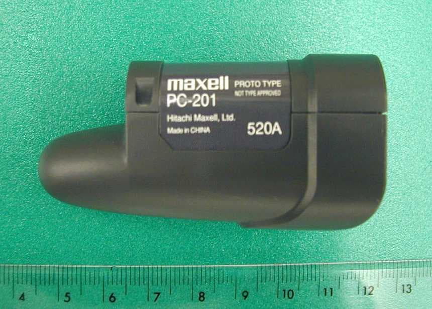
NEEDP02
May 29, 2006Digital Pen including Bluetooth transmitter
Equipment Class
JBP - Part 15 Class B Computing Device Peripheral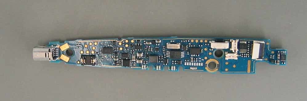
NEEDP01
Mar 01, 2004Digital Pen With Bluetooth
Equipment Class
JBP - Part 15 Class B Computing Device Peripheral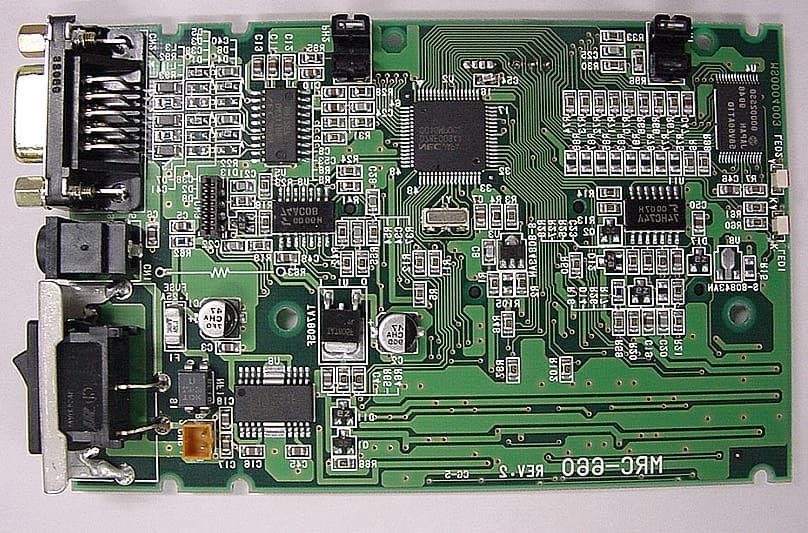
NEEA02
Sep 25, 2000IC Card Reader/Writer
Equipment Class
JBP - Part 15 Class B Computing Device Peripheral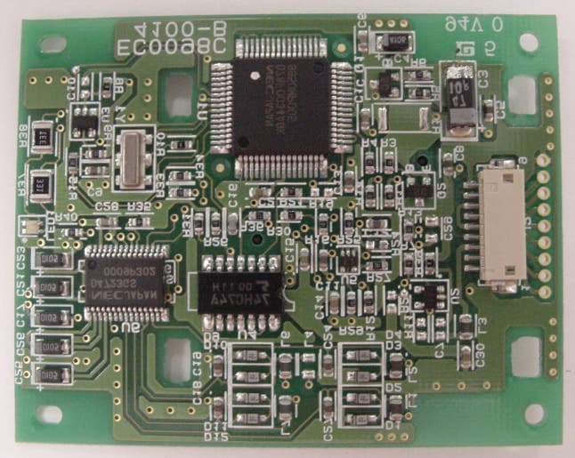
NEEM03
Jun 20, 2000Smart Card Reader/Writer
Equipment Class
JBP - Part 15 Class B Computing Device PeripheralNEEM02
Oct 20, 1997JBP - Part 15 Class B Computing Device Peripheral
Equipment Class
JBP - Part 15 Class B Computing Device Peripheral