NEEM03Smart Card Reader/Writer
Hitachi Maxell Ltd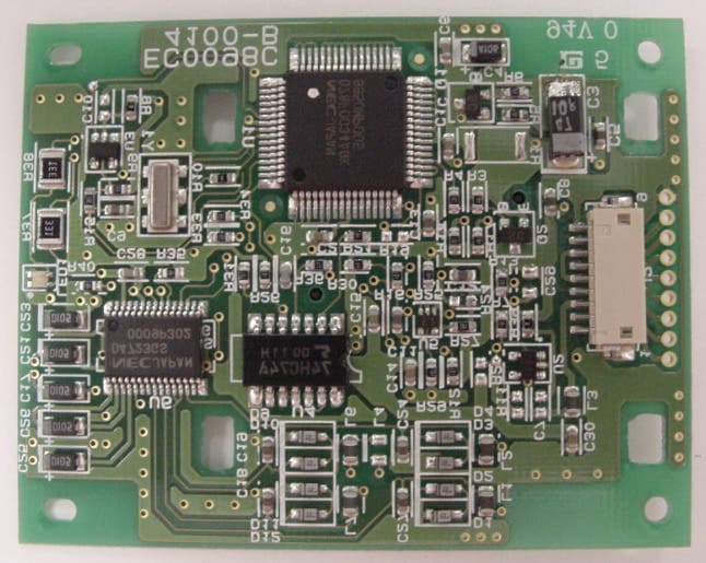
Click to zoom
Application Details
- Equipment Class
- JBP - Part 15 Class B Computing Device Peripheral
- Date of Grant
- Jun 20, 2000
- Application Purpose
- Original Equipment
- Date of Application
- Jun 04, 2000
- Equipment Note
- Smart Card Reader/Writer
- Company
- Hitachi Maxell Ltd
- Country
- Japan
Documents & Files
Document Text
Text extracted from the exhibit documents filed with the FCC. Open a document above to read the original.
Users Manual
EXHIBITB NEEM03 DRAFT Contents & Connection to the PC Number R/W (M-360M, Cable is attached) 1 To PC PS/2 port (mouse port or keyboard port) To mouse or Keyboard To PC serial port Power & RS-232C cable LED R/W IC card insertion slot USERMANUAL NEEM03 DRAFT How to use Completely insert the IC card with contact on the upper surface, contact side first, until it reaches the end of the IC card slot. The LED will blink green. LED Green light on: R/W power on Green light blinks: IC card is inserted Red light on: IC cart power on, active NEEM03 DRAFT Caution Failure to do the following may result in a decrease in performance of the apparatus, trouble, breakage, deformation, discoloring, electric shock, smoke, burning, or other dangers Do not disassemble or modify the product. Do not use this apparatus in moist or dusty environments. Do not leave this apparatus in high temperature or high humidity environments and do not exposed to direct sunlight. Do not subject the apparatus to severe mechanical shocks. Do not insert metallic plates, plastics and papers into card slot. Do not insert cards that are out of specifications. product . Do not insert IC card upside down, do not insert IC card revers direction, especially embossed card. NEEM03 DRAFT General specifications Model M-360M Card insertion/ejection Manual/manual(durability: 100K passes) Acceptable IC card IC card conforming to ISO7816 with “T=0”, “T=1”. Note : No Vpp control. The IC card must be warped or bent under 2mm. Host interface Based on RS-232C interface, Asynchronous Power supply DC5V5%, 110mA Max. (Supplied from PC PS/2 port) Outer dimensions 76mm105mm23mm (Cable is not included) Weight About 160 (Cable is not included) Operating conditions 050 1085%RH (No condensation Indoor use only Storage conditions -1060 1090%RH (No condensation) NEEM03 DRAFT This equipment has been tested and found to comply with the limits for a Class B digital device, pursuant to Part 15 of the FCC Rules. These limits are designed to provide reasonable protection against harmful interference in a residential installation. This equipment generates, uses and can radiate radio frequency energy and, if not installed and used in accordance with instructions, may cause harmful interference to radio communications. However, there is no guarantee that interference will not occur in a particular installation. If this equipment interferes with radio or television reception, which can be determined by turning the equipment off and on, the user is encouraged to try to eliminate the interference by one or more of the following measures: - Reorient or relocate the receiving antenna. - Increase the separation between the equipment and receiver. - Connect the equipment into an outlet on a circuit different from that to which the receiver is connected. - Consult the dealer or an experienced radio/TV technician for help. NEEM03 DRAFT This device complies with Part 15 of the FCC Rules/ Operation is subject to the following two conditions: (1) this device may not cause harmful interference, and (2) this device must accept any interference receive including interference that may cause undesired operation. CHANGES OR MODIFICATIONS NOT EXPRESSLY APPLOVED BY THE MANUFACTURER FOR COMPLIANCE COULD VOID THE USER'S AUTHORITY TO OPERATE THE EQUIPMENT.
External Photos
EXHIBITE Photo –1 ExternalView Photo –2 ExternalView Photo –3FrontView Photo –4SideView Photo –5RearView Photo –6TopView Photo –7BottomView Photo –8Top Cover Removed Photo –9Bottom Cover & PC Board Photo –10IC Card Connecter & PC Board Photo –11PC Board(Surface View) Photo –12PC Board(Back View)
ID Label/Location Info
EXHIBITA FCC ID: NEEM03 BOTTOM SURFACE FCC Label 40 17 49 42 Unit: mm
Operational Description
EXHIBITC FCC ID: NEEM03 PRODUCT SPECIFICATIONS Name: Manual Type Smart Card Reader/Writer Model: M-360M Hitachi, Ltd. Hitachi Maxell, Ltd. FCC ID: NEEM03 - 1 - Contents page 1. Outline --------------------------------------------------------------------------------------2 2. General Specifications -----------------------------------------------------------------2 3. Composition ---------------------------------------------------------------------------2 4. Interface --------------------------------------------------------------------------------3 5. Device Dimensions ----------------------------------------------------------------------4 Specifications will be changed without notice for improvement of the product. FCC ID: NEEM03 - 2 - 1. Outline This product is a manual insertion/ejection smart card reader/writer(R/W) to organize smart card system with PC. 2. General Specifications Name Manual Type Smart Card Reader/Writer Model M-360M Card insertion/ejection manual insertion/manual ejection Applicable smart card Smart card conforming to ISO7816 with “T=0” and “T=1” protocol. But, use it after you confirm conformity with a smart card to use, and this product. Note: No Vpp control. And maximum value for card warp 2.0mm. Applicable PC DOS/V PC (IBM A/T compatible) Applicable OS Windous95/98 Interface Serial interface (conforming RS-232C D-sub 9pin) Power supply DC5V5%, 110mA max. (Supplied from PC PS/2 port) Durability Smart card insertion/ejection 100,000passes(number of insertion/ejection times, warranty for 6 months after supply) Outer dimensions 76mm(W) 105mm(D) 23mm(H) (cable is not included) Weight about 160g (cable is included) Operating conditions 050 1085%RH (No condensation) Storage conditions -1060 1090%RH (No condensation) 3. Composition Following figure shows block diagram of R/W. PC PC I/F RS-232C Line Driver/Receiver LED MPU DCV Smart Card I/F Smart Card R/W(M-360M) X-tal (7.1MHz) Clock (7.1MHz or 3.55MHz) Vcc Reset Clock I/O GND PC FCC ID: NEEM03 - 3 - 4. Interface 4.1 PC interface Following table shows data transmission specification between PC and R/W. Table. Data transmission specifications between PC-R/W # Item Specifications 1 Transmission method half duplex transmission method 2 Character format STDataPSP STstart bit 1 bit Datadata bit 8 bit P parity bit 1 bit SPstop bit 1 bit 3 Synchronous method Asynchronous method(RS-232C,non-procedural) 4 Transfer rate 9600bps, 19200bps, 38400bps 5 Error detection vertical parity(even number) horizontal parity(exclusive OR) 6 Bit detection LSB first positive logic Table. Pin assaign of RS-232C connector (D-sub 9pin) Signal direction Pin No. Pin Name R/W PC 1 2 RD 3 SD 4 5 SG 6 DR 7 8 CS 9 4.2 Smart card interface Following table shows data transmission specification between R/W and smart card. Table. Data transmission specifications between R/W-Smart card # Item Specifications 1 Transmission method half duplex transmission method 2 Character format STDataPGT ST: start bit 1 bit Data: data bit 8 bit P : parity bit 1 bit GT : guard time variable 3 Synchronous method Asynchronous method 4 Transfer rate 9600bps, 19200bps, 38400bps 5 Error detection vertical parity LSB first: even number MSB first: odd number horizontal parity(exclusive OR) 6 Bit detection LSB first positive logic or MSB first negative logic 7 Card power supply 5V10% 8 Card supply clock 3.55MHz3%, 7.10MHz3% +5V +5V +5VVCCVCC VCC VCC VCC VCC VCC VCC VCC VCC ICC_Vcc ICC_RST ICC_CLK ICC_GND ICC_I/O JAE SD DR RS CS DUAL LED 3 green red RD ER 2 1 SG +5V GND C8 1uF R4 1k R15 30k C9 1uF R3 100k C6 0.1uF Q2 A1121SC R37 330 1/4W R12 10k R13 10k R14 10k R17 100k C11 22pF R31 1M R34 10k R33 10k R35 100k R21 100 R9 10k R26 10k R36 220 R6 1k R5 100k C5 1uF D9 MA8150 D4 MA8150 D11 MA8150 D3 MA8150 D12 MA8150 D10 MA8150 R16 100 Q1 A1121SC C1 0.1uF C2 0.1uF R30 1M R10 0 C18 330p C27 330p C24 330p C25 1uF + C26 1uF + C21 1uF + C17 1uF + C23 1uF + C28 0.1uF R27 68 U5A TC7S08FU 1 4 2 5 3 C14 0.1uF L1 ACB2012L-030 L2 ACB2012L-030 L3 ACB2012L-030 L6 ACB2012L-030 L7 ACB2012L-030 C12 10pF LED1 14 C19 330p D2 MA8150 D1 MA8150 R25 100k R29 100k U4A 74HC74 D 2 Q 5 CLK 3 PR 4 Q 6 CL 1 C15 0.1uF U4B 74HC74 D 12 Q 9 CLK 11 VCC 14 GND 7 PR 10 Q 8 CL 13 C16 1000pF R8 0 R7 10k R39 0 C30 0.1uF C3 47uF +C4 10uF + R38 330 1/4W 23 R40 100k J1 1 2 3 4 5 6 7 8 9 10 J2 1 2 3 4 5 6 7 8 9 U6 uPD4723 VDD 1 C1+ 2 VCC 3 C1- 4 C5+ 5 GND 6 C5- 7 DI1 8 DI2 9 DI3 10 RO1 11 RO2 12 RO3 13 NC 14 NC 15 NC 16 NC 17 RI3 18 RI2 19 RI1 20 DO3 21 DO2 22 DO1 23 EN 24 VCHA 25 STBY 26 VSS 27 C4- 28 GND 29 C4+ 30 U1 uPD780034 VDD0 10 VDD1 24 VSS0 9 VSS1 42 IC 39 AVDD 35 AVSS 25 AVREF 34 P40/AD0 57 P41/AD1 58 P42/AD2 59 P43/AD3 60 P44/AD4 61 P45/AD5 62 P46/AD6 63 P47/AD7 64 P50/A8 1 P51/A9 2 P52/A10 3 P53/A11 4 P54/A12 5 P55/A13 6 P56/A14 7 P57/A15 8 P17/ANI7 26 P16/ANI6 27 P15/ANI5 28 P14/ANI4 29 P13/ANI3 30 P11/ANI1 32 P12/ANI2 31 P10/ANI0 33 P64/RD 53 P65/WR 54 P66/WAIT 55 P67/ASTB 56 P30 11 P31 12 P32/SDA0 13 P33/SCL0 14 P34 15 P35 16 P36 17 RESET 36 XT2 37 XT1 38 X2 40 X1 41 P20/SI30 18 P21/SO30 19 P22/SCK30 20 P23/RXD0 21 P24/TXD0 22 P25/ASCK0 23 P70/TI00/TO0 47 P71/TI01 48 P72/TI50/TO50 49 P73/TI51/TO51 50 P74/PCL 51 P75/BUZ 52 P00/INTP0 43 P02/INTP2 45 P01/INTP1 44 P03/INTP3/ADTRG 46 U3 S-80842ANMP OUT 1 VDD 2 VSS 3 NC 5 NC 4 U2 S-80842ANMP OUT 1 VDD 2 VSS 3 NC 5 NC 4 C13 33pF Y1 M-360M Circuit Diagram B 11Tuesday, May 23, 2000 FCC ID : NEEM03 Title SizeDocument NumberRev Date:Sheet of
Test Report
EXHIBITD
Contact Information
Applicant
Masaru Kamemoto(General Manager, Digital Pen Division)
Technical Contact
Hitachi Maxell, Ltd.Masahiro Oohashi
[email protected]0297-24-7773
6139-1, Onogomachi · Mitsukaido · Japan
Non-Technical Contact
Hitachi Maxell, Ltd.Kazuya Fukunaga
[email protected]0297-24-7773
Technical Specifications
| # | Rule Parts | Frequency Range | Power Output |
|---|---|---|---|
| 1 | 15B | - | - |
Other Applications from Hitachi Maxell Ltd
NEEDP02
May 29, 2006Digital Pen including Bluetooth transmitter
Equipment Class
JBP - Part 15 Class B Computing Device Peripheral
NEEDP01
Mar 01, 2004Digital Pen With Bluetooth
Equipment Class
JBP - Part 15 Class B Computing Device Peripheral
NEEE01
Jan 22, 2001USB Read / Write Module
Equipment Class
DXX - Part 15 Low Power Communication Device Transmitter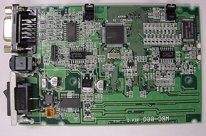
NEEA02
Sep 25, 2000IC Card Reader/Writer
Equipment Class
JBP - Part 15 Class B Computing Device PeripheralNEEM02
Oct 20, 1997JBP - Part 15 Class B Computing Device Peripheral
Equipment Class
JBP - Part 15 Class B Computing Device Peripheral