NJA-IQ160Industrial Fluid Level Sensor Transmitter
Siemens Canada Ltd. - Siemens Milltronics Process Instruments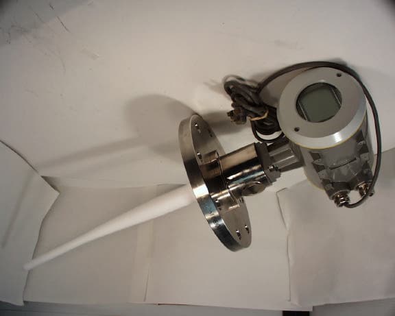
Click to zoom
Application Details
- Equipment Class
- DXX - Part 15 Low Power Communication Device Transmitter
- Date of Grant
- Aug 09, 1998
- Application Purpose
- Original Equipment
- Date of Application
- Jul 06, 1998
- Equipment Note
- Industrial Fluid Level Sensor Transmitter
- Frequency Range
- 6300.00000000 - 6300.00000000
- Country
- Canada
Documents & Files
Document Text
Text extracted from the exhibit documents filed with the FCC. Open a document above to read the original.
Users Manual
33455500 Rev1.0 hank you for purchasing Milltronicsí products. We endeavour to design equipment that is simple to use and reliable in its operation, with the aim of satisfying our customers' needs. Milltronics has been designing and manufacturing process equipment since 1954. Our fields of expertise include ultrasonic and capacitance level measurement, in-line weighing of dry bulk solids and motion sensing. Milltronics is established world wide through associate offices and representatives. Our network is continually being refined to provide our customers with first rate sales information, engineering assistance and after sales support. For more details on our products and service, please contact us and we will provide you with a listing of the offices or representatives nearest you. T _ PL-5503 TABLE OF CONTENTS GENERAL INFORMATION About This Manual.................................................................................................5 About IQ Radar 160...............................................................................................6 SPECIFICATIONS IQ Radar 160...........................................................................................................7 INSTALLATION Location....................................................................................................................9 Dimensions............................................................................................................ 10 Mounting................................................................................................................ 11 Flanged......................................................................................................... 11 Extension Requirements........................................................................... 12 Rod Assembly............................................................................................. 13 Interconnection .................................................................................................. 14 Terminal Block Layout............................................................................... 14 Wiring............................................................................................................. 15 START UP Overview................................................................................................................ 17 Display and Keypad............................................................................................ 19 Local Operation.................................................................................................... 20 Run Display.................................................................................................. 20 Run Keypad................................................................................................. 21 Program Display.......................................................................................... 22 Program Keypad......................................................................................... 23 Local Programming.................................................................................... 24 OPERATION Overview................................................................................................................ 27 Transceiver............................................................................................................ 28 Blanking................................................................................................................. 29 Loss of Echo......................................................................................................... 30 Analog Output...................................................................................................... 31 Programming............................................................................................... 31 Run................................................................................................................. 31 Fail-safe......................................................................................................... 32 Run / Program...................................................................................................... 32 Application Example........................................................................................... 33 PARAMETER DESCRIPTION ........................................................................................... 35 TROUBLESHOOTING ........................................................................................................ 41 MAINTENANCE ................................................................................................................... 43 APPENDICES Alphabetical Parameter List.............................................................................. 45 Programming Chart ........................................................................................... 46 PL-5504 _ PL-5505 GENERAL L INFO. _ GENERAL INFORMATION ABOUT THIS MANUAL It is essential that this manual be referred to for proper installation and operation of your IQ Radar 160. Installationgives you step-by-step direction for the installation and interconnection of your IQ Radar 160. Start-upinstructs you in how to operate the keypad, program the unit and read the display. Operationdescribes the operation of the IQ Radar 160, detailing the interoperation of the salient features. Applications looks at the IQ Radar 160 from a practical point of view, using a typical application example. Parameters lists the parameters available to you, with a description of their function and use. You are urged to read this section to familiarize yourself with the parameters available to you and get your IQ Radar 160 working to its fullest. Troubleshootingtabulates symptoms, causes and actions to common installation and application problems that you might encounter. Hopefully you will never have to read this section…
Text truncated - open the document above for the full version.
Users Manual
Milltronics Ltd. 1954 Technology Drive, P.O. Box 4225 Peterborough, ON Canada K9J 7B1 Tel: (705) 745-2431 Fax: (705) 741-0466 Internet: http://www.milltronics.com Instruction Manual Addendum Information to User NOTE: This equipment has been tested and found to comply with the limits for a Class A digital device, pursuant to Part 15 of the FCC Rules. These limits are designed to provided reasonable protection against harmful interference when the equipment is operated in a commercial environment. This equipment generates, uses, and can radiate radio frequency energy and, if not installed and used in accordance with the instruction manual, may cause harmful interference to radio communications. Operation of this equipment in a residential area is likely to cause harmful interference in which case the user will be required to correct the interference at his own expense. CAUTION: Changes or modifications not expressly approved by Milltronics Ltd., the party responsible for compliance, could void the user’s authority to operate the equipment.
Cover Letter(s)
July 02, 1998 FEDERAL COMMUNICATIONS COMMISSION 7435 Oakland Mills Road Columbia, MD 21046 USA Subject:Certification Application under FCC Part 15, Subpart C, Para. 15.209, Low Power Communication Device Transmitters Operating at 6.3 GHz. Applicant:MILLTRONICS Product:Milltronics Radar Level Gauge (6.3 GHz) Model:IQ RADAR 160 (AC) FCC ID:NJA-IQ160 Dear Sir/Madam, As appointed agent for MILLTRONICS, please find attached electronic files of the engineering report and all exhibits per FCC requirements. The FCC Form 159 and a check of US $1025.00 have been concurrently sent to Mellon Bank with this application. Grant Limitation: The FCC Certification of the Milltronics IQ RADAR 160 (AC) is applied for being used in a vented or non-vented metal tanks with or without internal stilling wells (typical metal: stainless steel) If you have any queries, please do not hesitate to contact us by our TOLL FREE numbers: OUR TELEPHONE NO.:1-800-263-7670 Yours truly, Tri Minh Luu, P. Eng., V.P., Engineering TML/AK Encl. April 20, 1998 Federal Communications Commission Oakland Mills Road Columbia, MD 21046 U.S.A. Subject:Request for withholding from public disclosure the schematic diagrams and system block diagrams pursuant to an application for certification. Applicant:Milltronics Ltd. Product:Milltronics Radar Level Gauge Model:IQ RADAR 160 FCC ID:NJA-IQ160 Dear Sir/Madam, We, Milltronics Ltd., would like to request that the schematic diagrams and system block diagrams, submitted with the application for certification be withheld from public disclosure as per Section 0.459 of FCC Rules. This request is made under the provisions of Section 0.457(d) of the Commission’s Rules, and Section 552(b)(4) of the Freedom of Information Act. These sections authorize as a withholding from public inspection, materials which would be privileged as a matter of law if retained by the person submitting them, and materials which would not customarily be released to the public by that person. The detailed confidential materials are listed as follows: No.Title Drawing No.Sheet No. 1MILLTRONICS IQ RADAR 160 Block Diagram -- 2IQ RADAR 160 MICROWAVE0-24751418-ZS-022 3PART LIST--1 to 4 If you have any queries, please do not hesitate to contact us. Yours truly, A.M.Kormos Product & Systems Coordinator Milltronics Ltd. 1954 Technology Drive, P.O. Box 4225 Peterborough, ON Canada K9J 7B1 Tel: (705) 745-2431 Fax: (705) 741-0466 Internet: http://www.milltronics.com Date:May 26, 1997 To:Victor Kee From:A.M.Kormos Subject:Authority to Act as an Agent to Federal Communications Commission I hereby appoint UltraTech Engineering Labs Inc. (UltraTech) to act as my agent in preparation of this application to F.C.C. for authourization of equipment under F.C.C. Rules. I also certify that the information provided, properly described the device or system for which authourization is required. Dated the 23rd day of May, 1997 Applicant: Milltronics Ltd. By: A.M.Kormos Milltronics Ltd. 1954 Technology Drive, P.O. Box 4225 Peterborough, ON Canada K9J 7B1 Tel: (705) 745-2431 Fax: (705) 741-0466 Internet: http://www.milltronics.com
External Photos
MILLTRONICS IQ-RADAR 160 MILLTRONICS IQ-RADAR 160 MILLTRONICS IQ-RADAR 160
ID Label/Location Info
TOLERANCESUNLESSOTHERWISENOTED ANGLES FRACTIONS APPROVEDBY CHECKEDBY DRAWNBY DRAWINGSCALE 3PLACEDECIMAL 2PLACEDECIMAL 1PLACEDECIMAL REVISIONDESCRIPTION JOBNo. THIRDANGLEPROJECTION PLOTAT FILENo. No. OFSHEET PETERBOROUGH,ONTARIO,CANADA. DRAWINGNo. REV. APPRO.DWGBYDATE ±0.010" ±0.002" ±0.030" ±0.5° ±0.030" 0 FORISSUE APRIL 21/98
ID Label/Location Info
211 mm (8.3") 32 mm (1.25) 245 mm (9.6 ") 412 mm (16.3") 136 mm (5.4") 75 mm (3.0") TEFLON ANTENNA EXTENSION OPTIONAL TEFLON EXTENSIONS 2, 4 LONG TEFLON ANTENNA BASE C/W 1 NPT MOUNTING THREAD STAINLESS STEEL FLANGE - OPTIONAL SIZES - ANSI 2, 3, 4 - DIN 50, 80, 100 - 3 TRI-CLAMP GLASS VIEWING WINDOW ENCLOSURE POWDER PAINTED CAST ALUMINUM MINIMUM THICKNESS .140 RESONATOR ENCLOSURE - POTTED WITH 2651-40FR ELECTROLESS NICKEL PLATED ALUMINUM NAMEPLATE 0.032 ALUMINUM USE4-#0 DRIVE PINS TO ATTACH LID TYP. OF 2 C/W EDPM OR SANTOPRENE GASKET CONDUIT ENTRY (TYP. OF 2) NICKEL PLATED BRASS AVAILABLE FITTING STANDARD M22/PG16 OR C/W ADAPTOR TO 1/2 NPT FITTING Ø 4.81
Internal Photos
MILLTRONICS IQ-RADAR 160 MILLTRONICS IQ-RADAR 160 MILLTRONICS IQ-RADAR 160 MILLTRONICS IQ-RADAR 160 MILLTRONICS IQ-RADAR 160 MILLTRONICS IQ-RADAR 160 MILLTRONICS IQ-RADAR 160 - RADIO PRINTED CIRCUIT BOARD MILLTRONICS IQ-RADAR 160 - RADIO PRINTED CIRCUIT BOARD MILLTRONICS IQ-RADAR 160 MILLTRONICS IQ-RADAR 160 MILLTRONICS IQ-RADAR 160
Test Report
July 02, 1998 FEDERAL COMMUNICATIONS COMMISSION 7435 Oakland Mills Road Columbia, MD 21046 USA Subject:Certification Application under FCC Part 15, Subpart C, Para. 15.209, Low Power Communication Device Transmitters Operating at 6.3 GHz. Applicant:MILLTRONICS Product:Milltronics Radar Level Gauge (6.3 GHz) Model:IQ RADAR 160 (AC) FCC ID:NJA-IQ160 Dear Sir/Madam, As appointed agent for MILLTRONICS, please find enclosed copies of the engineering report, authorization form, application form and a cheque of US $1025.00. Grant Limitation: The FCC Certification of the Milltronics IQ RADAR 160 (AC) is applied for being used in a vented or non-vented metal tanks with or without internal stilling wells (typical metal: stainless steel) If you have any queries, please do not hesitate to contact us by our TOLL FREE numbers: OUR TELEPHONE NO.:1-800-263-7670 Yours truly, Tri Minh Luu, P. Eng., V.P., Engineering TML/AK Encl. July 02, 1998 MILLTRONICS P.O. Box 4225, 1954 Technology Drive Peterborough, Ontario Canada, K9J 7B1 Attn.:Mr. Tony Kormos Subject:Certification Application under FCC Part 15, Subpart C, Para. 15.209, Low Power Communication Device Transmitters Operating at 6.3 GHz. Product:Milltronics Radar Level Gauge (6.3 GHz) Model:IQ RADAR 160 (AC) FCC ID:NJA-IQ160 Dear Mr. Kormos, The product sample, as provided by you, has been tested and found to comply with FCC Part 15, Subpart C, Para. 15.209, Low Power Communication Device Transmitters operating at 6.3 GHz. Grant Limitation: The FCC Certification of the Milltronics IQ RADAR 160 (AC) is applied for being used in a vented or non-vented metal tanks with or without internal stilling wells (typical metal: stainless steel) Enclosed you will find copies of the engineering report. If you have any queries, please do not hesitate to contact us. Yours truly, Tri Minh Luu, P. Eng., V.P., Engineering Encl. ENGINEERING TEST REPORT Milltronics Radar Level Gauge (6.3 GHz) MODEL NO.: IQ RADAR 160 (AC) FCC ID: NJA-IQ160 In Accordance With FCC PART 15, SUBPART C, PARA. 15.209 LOW POWER COMMUNICATION DEVICE TRANSMITTER OPERATING AT 6.3 GHz UltraTech FILE NO.: MIL-162FTX Tested for: MILLTRONICS P.O. Box 4225, 1954 Technology Drive Peterborough, Ontario Canada, K9J 7B1 Tested by: ULTRATECH GROUP OF LABS 4181 Sladeview Crescent, Unit 33 Mississauga, Ontario Canada L5L 5R2 REPORT PREPARED BY: Mr. Tri M. Luu, P.Eng. DATE: July 02, 1998 FCC PART 15, SUBPART C - LOW POWER COMMUNICATION DEVICE TRANSMITTERS Page 2 MILLTRONICS RADAR LEVEL GAUGE (6.3 GHz), MODEL IQ RADAR 160 (AC)FCC ID: NJA-IQ160 ULTRATECH GROUP OF LABSFile #: MIL-162FTX 4181 Sladeview Cres., Unit 33, Mississauga, Ontario, Canada L5L 5R2July 02, 1998 Tel. #: 905-569-2550, Fax. #: 905-569-2480, Wesite: http://www.ultratech-labs.com • Accredited by ITI (UK) Competent Body, NVLAP (USA) Accreditation Body & ACA/AUSTEL (Australian • Recognized/Listed by FCC (USA), Industry Canada (Canada) • All test results contained in this engineering test report are traceable to National Institute of Standards and Technology (NIST) TABLE OF CONTENTS 1.EXHIBIT 1 - SUMMARY OF TEST RESULTS & GENERAL STATEMENT OF CERTIFICATION........3 2.EXHIBIT 2 - GENERAL INFORMATION.......................................................................................................4 2.1.APPLICANT.....................................................................................................................................................4 2.2.MANUFACTURER............................................................................................................................................4 2.3.DESCRIPTION OF EQUIPMENT UNDER TEST.......................................................................................................4 2.4.RELATED SUBMITTAL(S)/GRANT.....................................................................................................................5 2.5.TEST METHODOLOGY.....................................................................................................................................5 2.6.TEST FACILITY...............................................................................................................................................6 2.7.UNITS OF MEASUREMENTS..............................................................................................................................6 3.EXHIBIT 3 - SYSTEM TEST CONFIGURATION..........................................................................................7 TEST SYSTEM DETAILS...............................................................................................................................................7 3.2.BLOCK DIAGRAMS FOR CONDUCTED & RADIATED EMISSION MEASUREMENTS..................................................8 3.2.1.Test setup for the transmitter mounted on top of a metal tank – final measurements...............................8 3.2.2.Test setup for the transmitter alone (not mounted on a metal tank ) - prescans.......................................9 3.3.PHOTOGRAPH FOR RF EMISSION MEASUREMENTS...........................................................................................10 3.3.1.TEST SETUP FOR AC POWER LINE CONDUCTED EMISSIONS MEASUREMENTS.........................10 3.3.2.TEST SETUP FOR RADIATED EMISSIONS MEASUREMENTS..........................................................12 3.3.3.Test setup for pre-scans in the anechoic enclosure................................................................................12 3.3.4.Test setup for the transmitter mounted on top of a metal tank................................................................14 3.4.JUSTIFICATION...............................................................................................................................................16 3.5.EUT OPERATING CONDITION.........................................................................................................................16 3.6.SPECIAL ACCESSORIES......…
Text truncated - open the document above for the full version.
Contact Information
Applicant
Thoai Bui(Approvals Specialist)
Technical Contact
ULTRATECH ENGINEERING LABS INC.TRI M LUU
[email protected]1-800-263-7670
4181 SLADEVIEW CRESCENT, UNIT 33 · MISSISSAUGA, ONTARIO · Canada
Non-Technical Contact
ULTRATECH ENGINEERING LABS INC.TRI M LUU
[email protected]1-800-263-7670
Test Firm
UltraTech Engineering Labs Inc.Tri Luu
Technical Specifications
| # | Rule Parts | Frequency Range | Power Output |
|---|---|---|---|
| 1 | - | 6.30 GHz - 6.30 GHz | - |
Other Applications from Siemens Canada Ltd. - Siemens Milltronics Process Instruments

NJA-LR250
Aug 07, 2014SITRANS LR250 Level Probing Radar
Equipment Class
LPR - Level Probing Radar
NJA-LR260
Jul 27, 2014SITRANS LR260 Level Probing Radar
Equipment Class
LPR - Level Probing Radar
NJA-LR560
Dec 22, 2010SITRANS LR560 Tank Level Probing Radar
Equipment Class
DXX - Part 15 Low Power Communication Device Transmitter
NJA-LR460
Mar 08, 2006SITRANS LR 460 TANK LEVEL PROBING RADAR
Equipment Class
DXT - Part 15 Low Power Transceiver, Rx Verified
NJA-LR400-1
Dec 07, 2004RADAR LAVEL GAUGE
Equipment Class
DXX - Part 15 Low Power Communication Device Transmitter