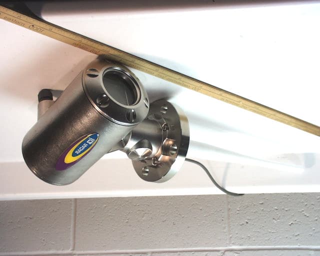
Click to zoom
Application Details
- Equipment Class
- DXX - Part 15 Low Power Communication Device Transmitter
- Date of Grant
- Apr 01, 2001
- Application Purpose
- Original Equipment
- Date of Application
- Jan 11, 2001
- Frequency Range
- 6300.00000000 - 6300.00000000
- Country
- Canada
Documents & Files
Document Text
Text extracted from the exhibit documents filed with the FCC. Open a document above to read the original.
Users Manual
PL-611IQ Radar 300Page 3 General Information Table of Contents Table of Contents Table of ContentsTable of Contents Table of Contents ................................ ................................................................ ................................................................ ................................................................ ................................................................ ................................................................ ................................................... ...................................... ................... 3 33 3 General Information General InformationGeneral Information General Information ................................ ................................................................ ................................................................ ................................................................ ................................................................ ................................................................ .............................................. ............................ .............. 7 77 7 The Manual ...................................................................................................................................... 7 IQ Radar 300..................................................................................................................................... 8 IQ Radar 300 Applications ............................................................................................................ 8 IQ Radar 300 Approvals and Certificates ...........................................................................................8 IQ Radar 300 Communication Systems ....................................................................................9 Optional SmartLinx ® cards .....................................................................................................................9 Specifications SpecificationsSpecifications Specifications ................................ ................................................................ ................................................................ ................................................................ ................................................................ ................................................................ ....................................................... .............................................. ....................... 11 1111 11 IQ Radar 300...................................................................................................................................11 Installation InstallationInstallation Installation................................ ................................................................ ................................................................ ................................................................ ................................................................ ................................................................ ............................................................. .......................................................... ............................. 15 1515 15 Location...........................................................................................................................................15 Dimensions: IQ Radar 300 with Rod Antenna.......................................................................16 Dimensions: Threaded Rod .......................................................................................................17 Dimensions: Horn .........................................................................................................................18 Dimensions: Waveguide Extension.........................................................................................19 Dimensions: Sanitary Horn ........................................................................................................20 Dimensions: Sanitary Rod ..........................................................................................................21 Dimensions: Waveguide.............................................................................................................22 Dimensions: Flanges ...................................................................................................................23 Mounting.........................................................................................................................................24 Threaded Rod Antenna........................................................................................................................ 25 Rod Assembly................................................................................................................................26 Rod Extension Requirements ............................................................................................................. 26 Mounting: Rod Assembly ...........................................................................................................27 Mounting: Manhole Covers .......................................................................................................28 Mounting: Horn Antennas..........................................................................................................28 Mounting: Waveguide Antenna ...............................................................................................29 Mounting: Stillpipe or Sidepipe ................................................................................................30 Smoothness ............................................................................................................................................ 30 Mounting: Horn with Waveguide Extensions.......................................................................31 Mounting: Sanitary Mounting ............................…
Text truncated - open the document above for the full version.
Cover Letter(s)
Dec. 27, 2000 FEDERAL COMMUNICATIONS COMMISSION 7435 Oakland Mills Road Columbia, MD 21046 USA Subject:FCC Certification Authorization Application under FCC PART 15, Subpart C, Sec. 15.209 - Low Power Transmitters operate at 6.3 GHz. Product:SIEMENS MILLTRONICS RADAR LEVEL GAUGE (6.3 GHZ) Model No.:IQ RADAR 300 FCC ID:NJA-IQ300 Dear Sir/Madam As appointed agent for SIEMENS MILLTRONICS PROCESS INSTRUMENTS INC., we would like to submit the application to the Federal Communications Commission for certification of the above product. Please review all necessary files uploaded to FCC OET site for detailed information. • Operational/Applicable Characteristics of Operation: The transmitter is only designed to radiate a 6.3 GHz RF signal inside a tank/ vessel, which may be made of any of material such as plastic, metal, concrete and etc..... The 6.3 GHz RF signal radiates downward to the bottom of the tank/vessel. With the support of proper enclosure shielding, no rf signal shall be radiated to the free space outside the tank with the distance more than 1 meter from the antenna. • Test Setup for Radiated Emissions: In all application, the IQ RADAR 300 is required to be mounted on top the tank/vessel with the antenna fitted inside the tank and faced downward to the bottom of the tank (ground). Therefore, the transmitter will be tested in the open area with the antenna points downward to the ground. This will represent the worst case among its application in any tanks/vessels. No RF emissions shall be observed at a 1 meter distance from the transmitting antenna. • Compliance with RF Exposure Requirements: In all application, the IQ RADAR 300 is required to be mounted on top the tank/vessel with the antenna fitted inside the tank. No users can possibly reach close to the antenna under its operation. Therefore, no RF Exposure Warning is necessary per FCC 2.1091 since the radius of tanks/vessels are always greater than the RF Safety Distance required. If you have any queries, please do not hesitate to contact us. Yours truly, Tri Minh Luu, P. Eng., V.P., Engineering Encl 2 3000 Bristol Circle Oakville, Ontario, Canada L6H 6G4 Telephone (905) 829-1570 Facsimile (905) 829-8050 Website: www.ultratech-labs.com Email: [email protected] [email protected] UltraTech Group of Labs
Cover Letter(s)
3 January, 2001 Federal Communications Commission Oakland Mills Road Columbia, MD 21046 U.S.A. Subject: Request for withholding from public disclosure the schematic diagrams and system block diagrams pursuant to an application for certification Applicant:Siemens Milltronics Process Instruments Inc. Product:Radar Level Gauge (6.3 GHz) Model No:IQ Radar 300 FCC ID:NJA-IQ300 Dear Sir/Madam, We, Siemens Milltronics Process Instruments Inc., would like to request that the schematic diagrams and system block diagrams submitted with the application for certification be withheld from public disclosure as per Section 0.459 of FCC rules. This request is made under the provisions of Section 0.457 of the Commission’s Rules, and Section 552 (b) (4) of the Freedom of Information Act. These sections authorize as a withholding from public inspection, materials which would be privileged as a matter of law if retained by the person submitting them, and materials which would not customarily be released to the public by that person. The detailed confidential materials are listed as follows: No.TitleDrawing No.Sheet No. 1Siemens Milltronics IQ Radar 300 Block Diagram 1 2Milltronics microwave board schematicRAD09-EK-01-V061 If you have any queries, please do not hesitate to contact us. Yours faithfully T. J. Adam Certification Specialist Tel. (705) 740-7009 E-mail: [email protected]
Cover Letter(s)
Date:3 January, 2001 To:Mr. Tri Luu From:T. J. Adam Subject:Authority to act as an agent to Federal Communications Commission I hereby appoint UltraTech Engineering Labs Inc. (UltraTech) to act as my agent in preparation of this application to the Federal Communications Commission (FCC) for authorization of the IQ 300 Microwave Level Radar under FCC rules. T J Adam Certification Specialist Tel. (705) 740-7009 E-mail: [email protected]
External Photos
Exhibit 11a - External Photos of the Siemens Milltronics IQ Radar 300 with Rod AntennaPhoto # 1 Exhibit 11a - External Photos of the Siemens Milltronics IQ Radar 300 with Rod AntennaPhoto # 2 Exhibit 11a - External Photos of the Siemens Milltronics IQ Radar 300 with Rod AntennaPhoto # 3 Exhibit 11a - External Photos of the Siemens Milltronics IQ Radar 300 with Rod AntennaPhoto # 4
External Photos
Exhibit 11b - External Photos of the Siemens Milltronics IQ Radar 300 with 8” Horn AntennaPhoto # 5 Exhibit 11b - External Photos of the Siemens Milltronics IQ Radar 300 with 8” Horn AntennaPhoto # 6 Exhibit 11b - External Photos of the Siemens Milltronics IQ Radar 300 with 8” Horn AntennaPhoto # 7 Exhibit 11b - External Photos of the Siemens Milltronics IQ Radar 300 with 8” Horn AntennaPhoto # 8
External Photos
Exhibit 11c - External Photos of the Siemens Milltronics IQ Radar 300 with 6” Horn AntennaPhoto # 9 Exhibit 11c - External Photos of the Siemens Milltronics IQ Radar 300 with 6” Horn AntennaPhoto # 10 Exhibit 11c - External Photos of the Siemens Milltronics IQ Radar 300 with 6” Horn AntennaPhoto # 11 Exhibit 11c - External Photos of the Siemens Milltronics IQ Radar 300 with 6” Horn AntennaPhoto # 12
External Photos
Exhibit 11d - External Photos of the Siemens Milltronics IQ Radar 300 with 4”Horn AntennaPhoto # 9 Exhibit 11d - External Photos of the Siemens Milltronics IQ Radar 300 with 4”Horn AntennaPhoto # 10 Exhibit 11d - External Photos of the Siemens Milltronics IQ Radar 300 with 4”Horn AntennaPhoto # 11 Exhibit 11d - External Photos of the Siemens Milltronics IQ Radar 300 with 4”Horn AntennaPhoto # 12
External Photos
Exhibit 11e - External Photos of the Siemens Milltronics IQ Radar 300 with 4” Sanitary Horn AntennaPhoto # 13 Exhibit 11e - External Photos of the Siemens Milltronics IQ Radar 300 with 4” Sanitary Horn AntennaPhoto # 14 Exhibit 11e - External Photos of the Siemens Milltronics IQ Radar 300 with 4” Sanitary Horn AntennaPhoto # 15 Exhibit 11e - External Photos of the Siemens Milltronics IQ Radar 300 with 4” Sanitary Horn AntennaPhoto # 16
ID Label/Location Info
Product Group 2425112200 S. NGUYEN PETERBOROUGH 09/JAN/01 RADAR FOR CONSTRUCTION0 T. ADAM R. CLYSDALE 1:1 11 1:1 A 24251122 0 RPC TA JAN 09/01 NOTES: 1) NAMEPLATE INFORMATION ABOVE TO APPEAR CENTRED ON ALUMINUM NAMEPLATE #24250943 2) COLOUR: ALL TEXT & ARTWORK TO BE SILVER ON BLACK BACKGROUND. 3) NO REVISIONS WITHOUT PRIOR APPROVALS AUTHORIZATION. 4) SERIAL NUMBER SHOWN IS FOR EXAMPLE ONLY. 5) ENGRAVING PROCESS IS Nd:YAG LASER MARKING. MILLTRONICS PART No. 24251122-00 SCALE 1:1 NOTE: HOLES & OUTLINES APPEAR FOR REF. ONLY SIEMENS I.Q. RADAR 300, FCC, CSA NAMEPLATE LASER MARKING DIAGRAM SERIAL # 12345678 SIEMENS MILLTRONICS P.I. PETERBOROUGH, ONTARIO CANADA INPUT: 24 – 230 V±15% , 40 – 70 Hz, 28 VA, 11 W OR 24 – 230 V,W±15%, 9 4.2" (REF.) 2.66" (REF.) AMB. TEMP.: – 40 C TO 60 C OUTPUT: 4–20 mA, RS485 ENCLOSURE: TYPE/NEMA 4X, 6 / IP67 MADE IN CANADA FCC ID: NJA-IQ 300 This device complies with part 15 of the FCC Rules. Operation is subject to the following two conditions: (1) This device may not cause harmful interference,and (2) This device must accept any interference received, including interference that may cause undesired operation.
Internal Photos
Exhibit 12(a) - Internal Photos of the Siemens Milltronics IQ Radar 300Photo # 1 Exhibit 12(a) - Internal Photos of the Siemens Milltronics IQ Radar 300Photo # 2 Exhibit 12(a) - Internal Photos of the Siemens Milltronics IQ Radar 300Photo # 3 6.3 GHz Radio Transmitter Board Exhibit 12(a) - Internal Photos of the Siemens Milltronics IQ Radar 300Photo # 4 6.3 GHz Radio Transmitter Board Exhibit 12(a) - Internal Photos of the Siemens Milltronics IQ Radar 300Photo # 5 Exhibit 12(a) - Internal Photos of the Siemens Milltronics IQ Radar 300Photo # 6 Exhibit 12(a) - Internal Photos of the Siemens Milltronics IQ Radar 300Photo # 7 Exhibit 12(a) - Internal Photos of the Siemens Milltronics IQ Radar 300Photo # 8
Internal Photos
Exhibit 12(b) - Internal Photos of the Siemens Milltronics IQ Radar 300Photo # 9 Exhibit 12(b) - Internal Photos of the Siemens Milltronics IQ Radar 300Photo # 10 Exhibit 12(b) - Internal Photos of the Siemens Milltronics IQ Radar 300Photo # 11 Exhibit 12(b) - Internal Photos of the Siemens Milltronics IQ Radar 300Photo # 12 Exhibit 12(b) - Internal Photos of the Siemens Milltronics IQ Radar 300Photo # 13 Exhibit 12(b) - Internal Photos of the Siemens Milltronics IQ Radar 300Photo # 14 Exhibit 12(b) - Internal Photos of the Siemens Milltronics IQ Radar 300Photo # 15 Exhibit 12(b) - Internal Photos of the Siemens Milltronics IQ Radar 300Photo # 16
Operational Description
Exhibit 20 - Technical DescriptionPage # 1 Siemens Milltronics IQ 300 Radar Technical Description, 3 January, 2001 Introduction Siemens Milltronics IQ 300 Radar is intended for use in process industries for the determination of material level in tanks and other process vessels. The principle used is pulse radar. The equipment is mounted at the top of the tank or vessel. A short pulse of microwave energy us transmitted towards the surface of the material to be measured. This pulse is reflected from the material surface, and re-transmitted back towards the antenna. The time of flight of the pulse is measured, and hence the distance of the material surface from the antenna is determined (radar principle). This is then used to calculate the level and/or volume of material in the tank or vessel. Technical Description Referring to the block diagram, the device may be divided into three sections, namely antenna, microwave section and signal processing. The signal processing consists of a microprocessor and suitable analog circuitry and digital logic to perform the following functions: • Timing • Digital signal processing • Local display • Digital communications • 4 to 20 mA signal output The antenna consists of either a dielectric rod antenna, a horn antenna or a waveguide. The microwave section performs the following functions: • Under control of the signal processing section, a short (1.5 ns) pulse at 6.3 GHz is generated every 2 μs • After a short delay a local oscillator generates a similar 6.3 GHz pulse which is mixed with the received echo • By continuously varying the above delay in a suitable manner, and sampling the returned echo once per transmit pulse with variable delay, the returned echo is transformed to an equivalent 22 kHz signal • This is processed using standard radar echo processing techniques to determine the position of the true echo Exhibit 20 - Technical DescriptionPage # 2 Siemens Milltronics IQ 300 Radar Microwave Transmitter – Description of Operation Refer to the schematic diagram RAD09-EK-01-V06. This schematic shows the microwave portion of the IQ 300 electronics. The microwave pulse is generated using a standard transistor oscillator in the following way: The transmitter burst is initiated by the rising edge of a logic signal on pin 2 of CON1. This pulse is coupled to a transistor oscillator circuit (T9) which produces a short high frequency burst at 6.3 GHz. The 6.3 GHz pulse is transmitted as a wave along the microstrip line, which acts as a waveguide, passes through an isolating coupler (between C17 and R32), then through a Wilkinson divider which directs the energy to the antenna cable via CON2. The antenna cable is directed to the waveguide transition (through encapsulant in the housing). The antenna cable is terminated into the waveguide transition, at which point the 6.3 GHz electromagnetic wave is directed to the antenna.
Test Report
Dec. 27, 2000 FEDERAL COMMUNICATIONS COMMISSION 7435 Oakland Mills Road Columbia, MD 21046 USA Subject:FCC Certification Authorization Application under FCC PART 15, Subpart C, Sec. 15.209 - Low Power Transmitters operate at 6.3 GHz. Product:SIEMENS MILLTRONICS RADAR LEVEL GAUGE (6.3 GHZ) Model No.:IQ RADAR 300 FCC ID:NJA-IQ300 Dear Sir/Madam As appointed agent for SIEMENS MILLTRONICS PROCESS INSTRUMENTS INC., we would like to submit the application to the Federal Communications Commission for certification of the above product. Please review all necessary files uploaded to FCC OET site for detailed information. • Operational/Applicable Characteristics of Operation: The transmitter is only designed to radiate a 6.3 GHz RF signal inside a tank/ vessel, which may be made of any of material such as plastic, metal, concrete and etc..... The 6.3 GHz RF signal radiates downward to the bottom of the tank/vessel. With the support of proper enclosure shielding, no rf signal shall be radiated to the free space outside the tank with the distance more than 1 meter from the antenna. • Test Setup for Radiated Emissions: In all application, the IQ RADAR 300 is required to be mounted on top the tank/vessel with the antenna fitted inside the tank and faced downward to the bottom of the tank (ground). Therefore, the transmitter will be tested in the open area with the antenna points downward to the ground. This will represent the worst case among its application in any tanks/vessels. No RF emissions shall be observed at a 1 meter distance from the transmitting antenna. • Compliance with RF Exposure Requirements: In all application, the IQ RADAR 300 is required to be mounted on top the tank/vessel with the antenna fitted inside the tank. No users can possibly reach close to the antenna under its operation. Therefore, no RF Exposure Warning is necessary per FCC 2.1091 since the radius of tanks/vessels are always greater than the RF Safety Distance required. If you have any queries, please do not hesitate to contact us. Yours truly, Tri Minh Luu, P. Eng., V.P., Engineering Encl 2 3000 Bristol Circle Oakville, Ontario, Canada L6H 6G4 Telephone (905) 829-1570 Facsimile (905) 829-8050 UltraTech Group of Labs Dec. 27, 2000 SIEMENS MILLTRONICS PROCESS INSTRUMENTS INC. P.O. Box 4225, 1954 Technology Drive Peterborough, Ontario Canada, K9J 7B1 Attn.:Mr. Craig Merchant Subject:FCC Certification Application Testing under FCC PART 15, Subpart C, Sec. 15.209 – Low Power Transmitters operate at 6.3 GHz. Product:SIEMENS MILLTRONICS RADAR LEVEL GAUGE (6.3 GHZ) Model No.:IQ RADAR 300 FCC ID:NJA-IQ300 Dear Mr. Merchant, The product sample, as provided by you, has been tested and found to comply with FCC PART 15, Subpart C, Sec. 15.209 - Low Power Transmitters operate at 6.3 GHz. • Operational/Applicable Characteristics of Operation: The transmitter is only designed to radiate a 6.3 GHz RF signal inside a tank/ vessel, which may be made of any of material such as plastic, metal, concrete and etc..... The 6.3 GHz RF signal radiates downward to the bottom of the tank/vessel. With the support of proper enclosure shielding, no rf signal shall be radiated to the free space outside the tank with the distance more than 1 meter from the antenna. • Test Setup for Radiated Emissions: In all application, the IQ RADAR 300 is required to be mounted on top the tank/vessel with the antenna fitted inside the tank and faced downward to the bottom of the tank (ground). Therefore, the transmitter will be tested in the open area with the antenna points downward to the ground. This will represent the worst case among its application in any tanks/vessels. No RF emissions shall be observed at a 1 meter distance from the transmitting antenna. • Compliance with RF Exposure Requirements: In all application, the IQ RADAR 300 is required to be mounted on top the tank/vessel with the antenna fitted inside the tank. No users can possibly reach close to the antenna under its operation. Therefore, no RF Exposure Warning is necessary per FCC 2.1091 since the radius of tanks/vessels are always greater than the RF Safety Distance required. If you have any queries, please do not hesitate to contact us. Yours truly, Tri Minh Luu, P. Eng., V.P., Engineering Encl 2 3000 Bristol Circle Oakville, Ontario, Canada L6H 6G4 Telephone (905) 829-1570 Facsimile (905) 829-8050 Website: www.ultratech-labs.com UltraTech Group of Labs SIEMENS MILLTRONICS RADAR LEVEL GAUGE (6.3 GHZ) Model No.: IQ RADAR 300 FCC ID: NJA-IQ300 Applicant: SIEMENS MILLTRONICS PROCESS INSTRUMENTS INC. P.O. Box 4225, 1954 Technology Drive Peterborough, Ontario Canada, K9J 7B1 In Accordance With FEDERAL COMMUNICATIONS COMMISSION (FCC) PART 15, SUBPART C, SEC. 15.209 Low Power Transmitters operates at 6.3 GHz UltraTech's File No.: MIL-206FCC This Test report is Issued under the Authority of Tri M. Luu, Professional Engineer, Vice President of Engineering UltraTech Group of Labs Date: Dec. 01, 2000 Report Prepared by: Tri M. Luu . Tested by: Hung Trinh Issued Date: Dec. 01, 2000Test Dates: Nov. 10-23, 2000 The results in this Test Report apply only to the sample(s) tested, and the sample tested is randomly selected. UltraTech 3000 Bristol Circle, Oakville, Ontario, Canada, L6H 6G4 Telephone (905) 829-1570 Facsimile (905) 829-8050 Website: www.ultrat4ech-labs.com Email: [email protected] FCC PART 15, SUBPART C, SEC. 15.209 - LOW POWER TRANSMITTERS Page 2 SIEMENS MILLTRONICS RADAR LEVEL GAUGE (6.3 GHZ), Model IIQ RADAR 300FCC ID: NJA-IQ300 ULTRATECH GROUP OF LABSFile #: MIL-206FCC 3000 Bristol Circle, Oakville, Ontario, Canada L6H 6G4Dec. 01, 2000 Tel. #: 905-829-1570, Fax. #: 905-829-8050, Email: [email protected], Website: http://www.ultratech-labs.com • Assessed by ITI (UK) Competent Body, NVLAP (USA) Accreditation Body & ACA/AUSTEL (Australia), VCCI (Japan) • Accredited by Industry Canada (Canada) under ACC-LAB (Europe/Canada MRA and APEC/Canada MRA) • Recognized/Listed by FCC (USA )…
Text truncated - open the document above for the full version.
Test Report
Exhibit 9 - Plots of Measurement DataPlot # 1 Remark:This plot shows the emission signal radiating toward the bottom of a tank/vessel, please note that this signal is not intended to radiate through air outside the tank/vessel. Exhibit 9 - Plots of Measurement DataPlot # 2 Remark:This plot shows the emission signal radiating toward the bottom of a tank/vessel, please note that this signal is not intended to radiate through air outside the tank/vessel. Exhibit 9 - Plots of Measurement DataPlot # 3 Remark:This plot shows the emission signal radiating toward the bottom of a tank/vessel, please note that this signal is not intended to radiate through air outside the tank/vessel. Exhibit 9 - Plots of Measurement DataPlot # 4 Remark:This plot shows the emission signal radiating toward the bottom of a tank/vessel, please note that this signal is not intended to radiate through air outside the tank/vessel. Exhibit 9 - Plots of Measurement DataPlot # 5 Remark:This plot shows the emission signal radiating toward the bottom of a tank/vessel, please note that this signal is not intended to radiate through air outside the tank/vessel. Exhibit 9 - Plots of Measurement DataPlot # 6 Remark:This plot shows the emission signal radiating toward the bottom of a tank/vessel, please note that this signal is not intended to radiate through air outside the tank/vessel.
Test Report
Exhibit 9 - Plots of Measurement DataPlot # 7 Remark:This plot shows the emission signal radiating toward the bottom of a tank/vessel, please note that this signal is not intended to radiate through air outside the tank/vessel. Exhibit 9 - Plots of Measurement DataPlot # 8 Remark:This plot shows the emission signal radiating toward the bottom of a tank/vessel, please note that this signal is not intended to radiate through air outside the tank/vessel. Exhibit 9 - Plots of Measurement DataPlot # 9 Remark:This plot shows the emission signal radiating toward the bottom of a tank/vessel, please note that this signal is not intended to radiate through air outside the tank/vessel. Exhibit 9 - Plots of Measurement DataPlot # 10 Remark:This plot shows the emission signal radiating toward the bottom of a tank/vessel, please note that this signal is not intended to radiate through air outside the tank/vessel. Exhibit 9 - Plots of Measurement DataPlot # 11 Exhibit 9 - Plots of Measurement DataPlot # 12
Test Setup Photos
Exhibit 10 - Photos of Test SetupPhoto # 1 10.1Setup for the AC Powerline Conducted Emission Measurements Exhibit 10 - Photos of Test SetupPhoto # 2 Exhibit 10 - Photos of Test SetupPhoto # 3 10.2Setup for the Signal and Spurious/Harmonic Emission Radiation at 1m and 3m Free Space with the EUT + Rod Antenna 10.2.1 RF Fundamental and Spurious/Harmonic Emissions inside a tank/vessel Remark:This setup is for observing the radiated emissions which radiates to the bottom of and inside the tank/vessel in a narrow path. Test was performed with a rod antenna. This setup does not represent the actual installation configuration. In the actual test configuration, the EUT is mounted on top of the tank/vessel and its antenna points downward to bottom of the tank/vessel. Exhibit 10 - Photos of Test SetupPhoto # 4 Exhibit 10 - Photos of Test SetupPhoto # 5 10.2.2 RF Fundamental and Spurious/Harmonic Emissions around the EUT at the distance 1 meter and 3 meters in the free space (this represents the worst case covering the actual installation on top of a tank/vessel) Test with Rod Antenna in its intended position Exhibit 10 - Photos of Test SetupPhoto # 6 10.3Setup for the Signal and Spurious/Harmonic Emission Radiation at 1m and 3m Free Space with the EUT + 8”, 6”, 4” and 4” Sanitary Horn Antennae 10.3.1 RF Fundamental and Spurious/Harmonic Emissions inside a tank/vessel Remark:This setup is for observing the radiated emissions which radiates to the bottom of and inside the tank/vessel in a narrow path. Test was performed with every horn antenna, one at a time. This setup does not represent the actual installation configuration. In the actual test configuration, the EUT is mounted on top of the tank/vessel and its antenna points downward to bottom of the tank/vessel. Exhibit 10 - Photos of Test SetupPhoto # 7 Exhibit 10 - Photos of Test SetupPhoto # 8 10.2.3 RF Fundamental and Spurious/Harmonic Emissions around the EUT at the distance 1 meter and 3 meters in the free space (this represents the worst case covering the actual installation on top of a tank/vessel) Test with 8”Horn Antenna in its intended position Exhibit 10 - Photos of Test SetupPhoto # 9 Test with 6”Horn Antenna in its intended position Exhibit 10 - Photos of Test SetupPhoto # 10 Test with 4”Horn Antenna in its intended position Exhibit 10 - Photos of Test SetupPhoto # 11 Test with 4” Sanitary Horn Antenna in its intended position Exhibit 10 - Photos of Test SetupPhoto # 12 10.4 Setup for the Signal and Spurious/Harmonic Emission Radiation at 1m and 3m Free Space with the mounted on top of a plastic container containing chemical liquid in a chemical plan. Tests per performed with different antennae. Exhibit 10 - Photos of Test SetupPhoto # 13 Exhibit 10 - Photos of Test SetupPhoto # 14
Contact Information
Applicant
Thoai Bui(Approvals Specialist)
Technical Contact
Ultratech Engineering Labs Inc.Tri M Luu
[email protected]1-877-765-4173
3000 Bristol Circle · Oakville, Ontario · Canada
Non-Technical Contact
Ultratech Engineering Labs Inc.Tri M Luu
[email protected]1-877-765-4173
Test Firm
UltraTech Engineering Labs Inc.Tri Luu
Technical Specifications
| # | Rule Parts | Frequency Range | Power Output |
|---|---|---|---|
| 1 | 15.209 | 6.30 GHz - 6.30 GHz | - |
Other Applications from Siemens Canada Ltd. - Siemens Milltronics Process Instruments

NJA-LR250
Aug 07, 2014SITRANS LR250 Level Probing Radar
Equipment Class
LPR - Level Probing Radar
NJA-LR260
Jul 27, 2014SITRANS LR260 Level Probing Radar
Equipment Class
LPR - Level Probing Radar
NJA-LR560
Dec 22, 2010SITRANS LR560 Tank Level Probing Radar
Equipment Class
DXX - Part 15 Low Power Communication Device Transmitter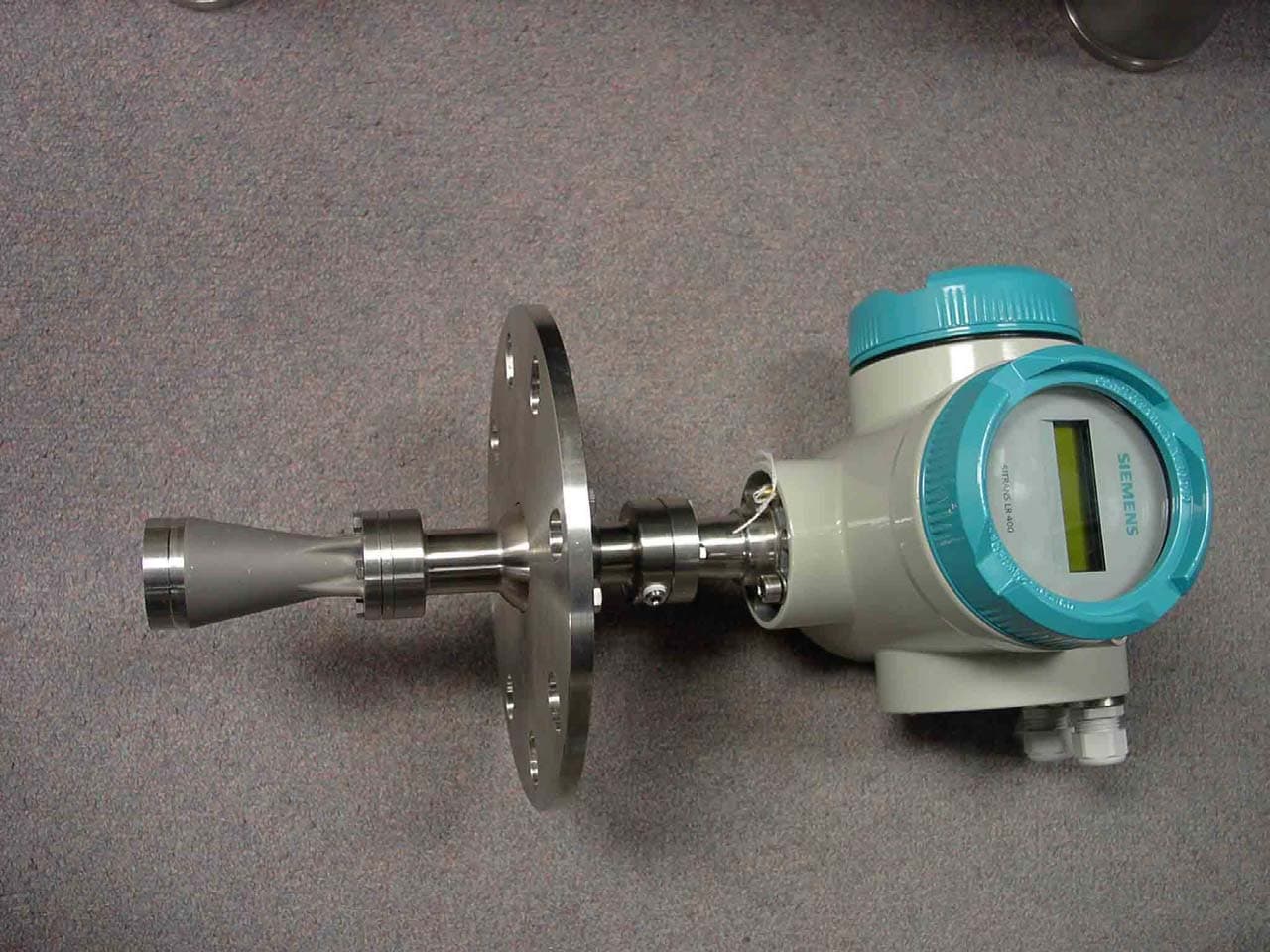
NJA-LR460
Mar 08, 2006SITRANS LR 460 TANK LEVEL PROBING RADAR
Equipment Class
DXT - Part 15 Low Power Transceiver, Rx Verified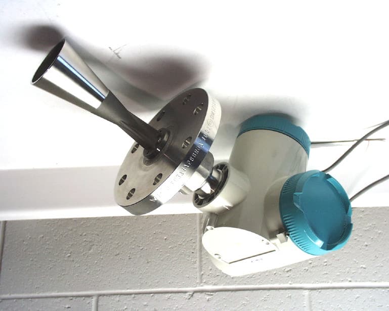
NJA-LR400-1
Dec 07, 2004RADAR LAVEL GAUGE
Equipment Class
DXX - Part 15 Low Power Communication Device Transmitter